HMI is very important things. Wondering what is HMI? Then it's a Human to Machine Interface. Basically interface includes the way for the user to operate the machine and to know vital parameters of the process. In mobile and web era application is becoming standard for under engagement. Every company is starting with their own apps.
Then why apps?
Because they are really handy to use, one can download the app and stay updated with news form the app owners. On top of that apps and website offers them a way to get presented in-front of user. Using buttons to do more complex things like multiplying two big numbers is very easy than writing a code for it.
And I believe this became the calculator app. Which represents data, takes input, do some operation on it and produces result.
Goal
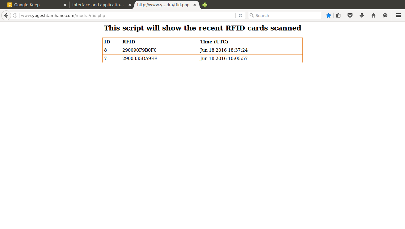
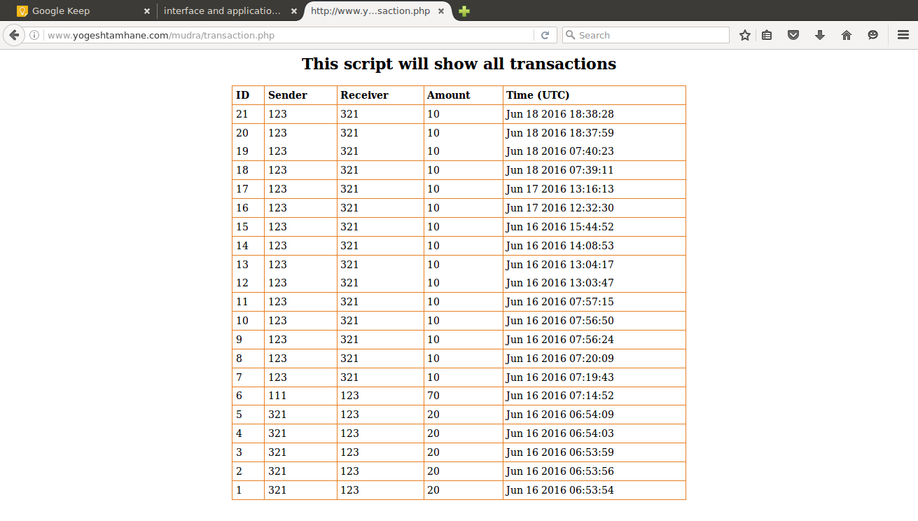
Designing the interface between my Mudra POS which is my final project and the server. Therefore the system will do this week in this week is it will take the input from RFID reader, packet that information into the POST request format and send it to the server. Server will take care of recording data send by the mudra POS and appended into existing table.
Getting started
As I've explained you about the things that I did in last assignment of interfacing the GSM module to micro-controller I'll be using that setup as the base for this week's assignment. Addition to the networking and communication setup I'll be interfacing RFID module which is one of the module in my final project which can read the RFID cards.
Step 1: Know about hardware
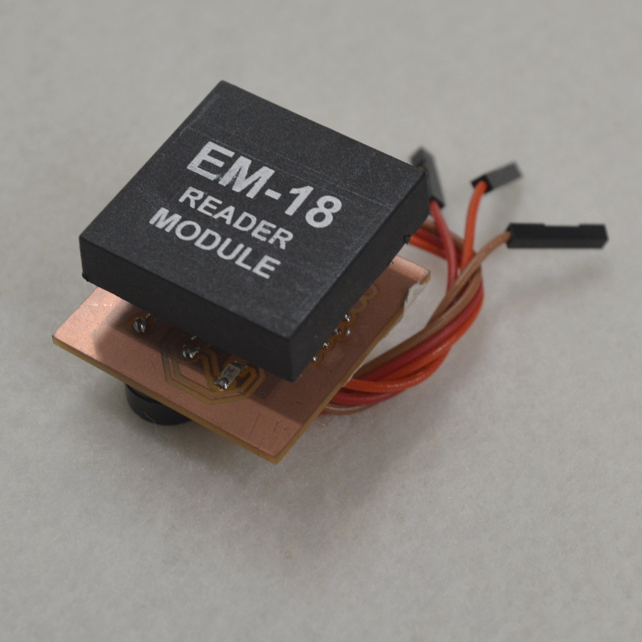
RFID module is the one which communicates via the RS-232 protocol and has got only transmitter pin to send data to the host micro-controller
| wire Color | Function | Connected to Atmega328 |
|---|---|---|
| Red | Vcc | Vcc |
| Brown | GND | GND |
| Orange | serial data out | PD0 |
Default communication baudrate for EM18 is 9600.
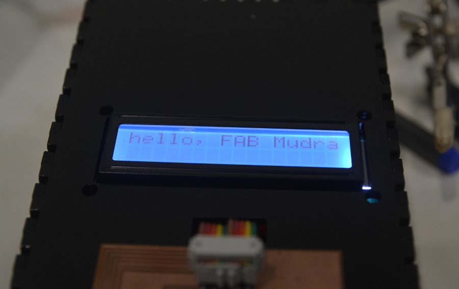
In addition to GSM module adn RFID I've used the LCD 16x2 character display in my output devices assignment which I'll be using to display promoting as well as few status messages. 16x2 LCD is working in 4 bit mode. On satsha kit I've added the LCD port identical configuration of the Prof. Neil's board in output devices week which is the 10 pin header.
Step 2: Complete Setup
As I explained the RFID module that I made, is added to the networking week's circuit and here's the result. This week I've pretty solid setup to work with which includes the communication module and the input module.
How I did connection? When I just have one physical USART on Atmega328.
Step 3: Writing code for RFID module
As I already have the program for POST request, now I just have to build up logic to read the 12 bytes data sent by the RFID module.
Basically i wanted to prompt user to scan his/her card using LCD or serial interface and then wait for the user to scan the card. The logic for doing this can be implemented with while loop. To read 12 bytes I did is I implemented a while loop and created the index variable, which is to care of how many bytes are entered through the defined serial port, how I did it is as soon as I received the data from the module I incremented the index variable and as the value of variable reached 12 I broke the while loop. Storing data while counting and reading is done using the array.
Step 4: Interface flow
Now I have both the codes ready with me, integration is next thing that I'll explain in this section.
As I studied the interface should be very easy to understand even by the non-technical person, if so he will become interested into the machine that you are dreaming of and it will fly, otherwise it people won't accept the device/machine.
- Greet the user
- Show the status message whether GSM network connected or not
- Show success or failure message if failed ask user to reset the POS.
- Then ask user to show his ID card.
- Give feedback whether card is got successfully scanned or not, is not then ask him/her to scan it once again
- Show "device is connecting to internet."
- Show status message internet connectivity
- While POS is POSTing the data to server show, "processing your request"
- When successful show him/her the message the may be card number and how to proceed
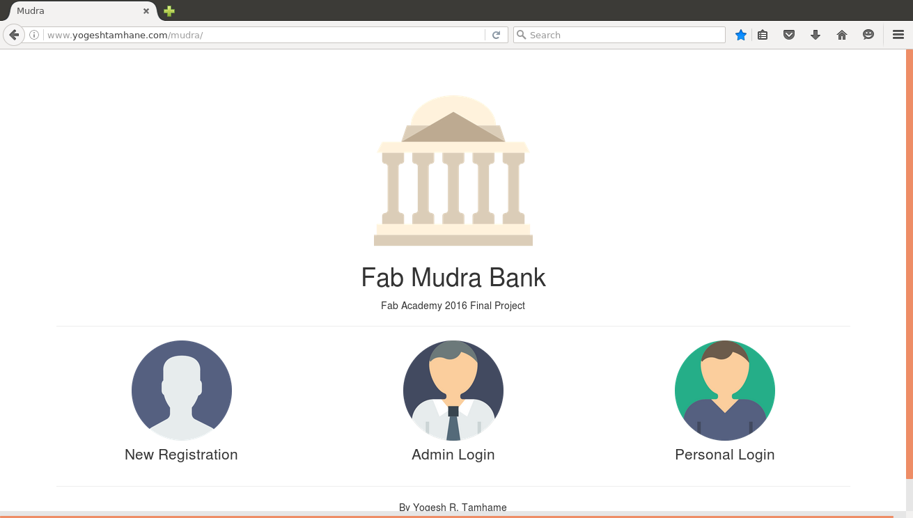
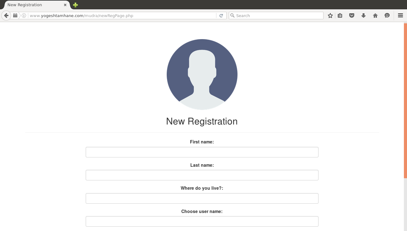
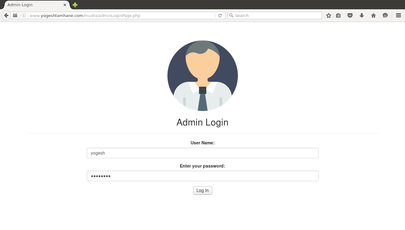
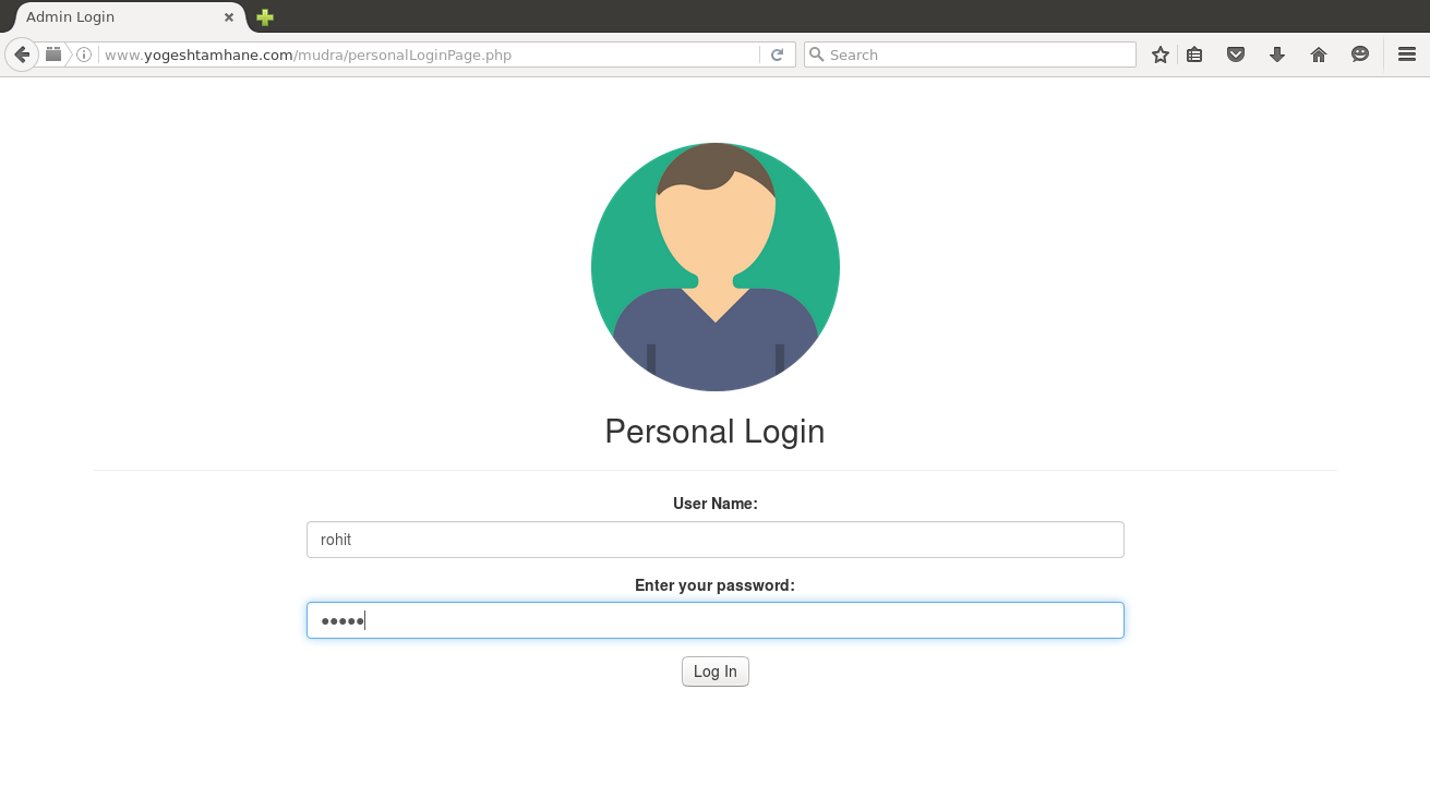
Photographs and Videos
Few other interfaces designed for my final project