Assignments
Make an in-circuit programmer
In the fourth week of Fab Academy the assignment was to make an in-circuit programmer
I decided to choose the Fab ISP Created by David A. Mellis.Simply because we had all the electric components for this board in our lab
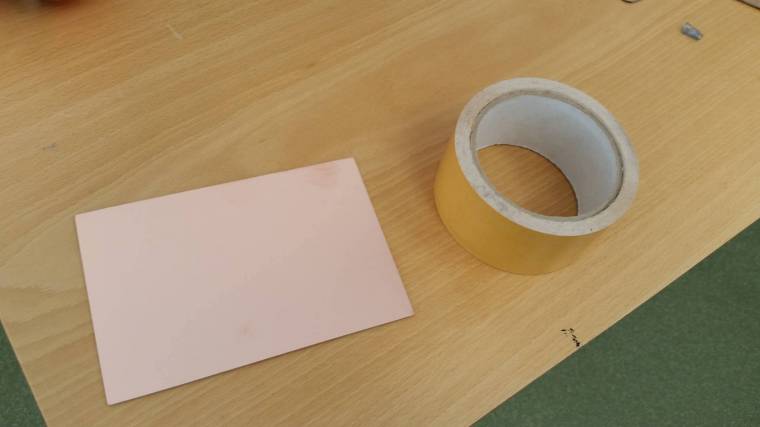
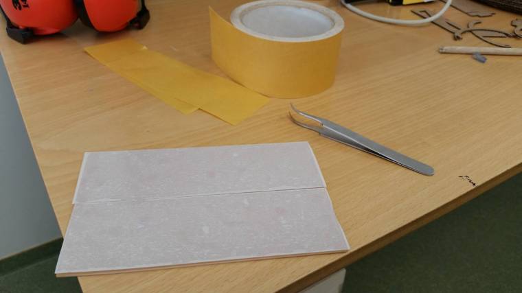
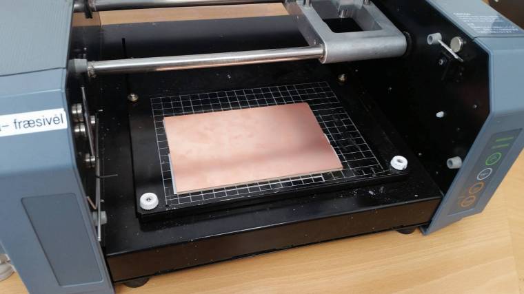
Preparation for the cut
We always have two circuit boards placed on the modela. There was one board already placed on the machine so me and Arnar grabbed another one, put double tape on it and put it on top of the first one

Next i downloaded the png files for the traces and outlines here and here
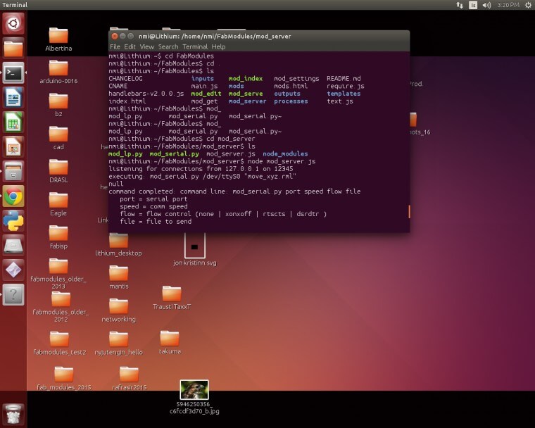
Our Roland Modela machine is connected to a computer using Linux, so it´s nice to use different kind of operating systems through out the Fab Academy
Next i turned on the server so the Fab Modules from the web could communicate with the port and control the modela
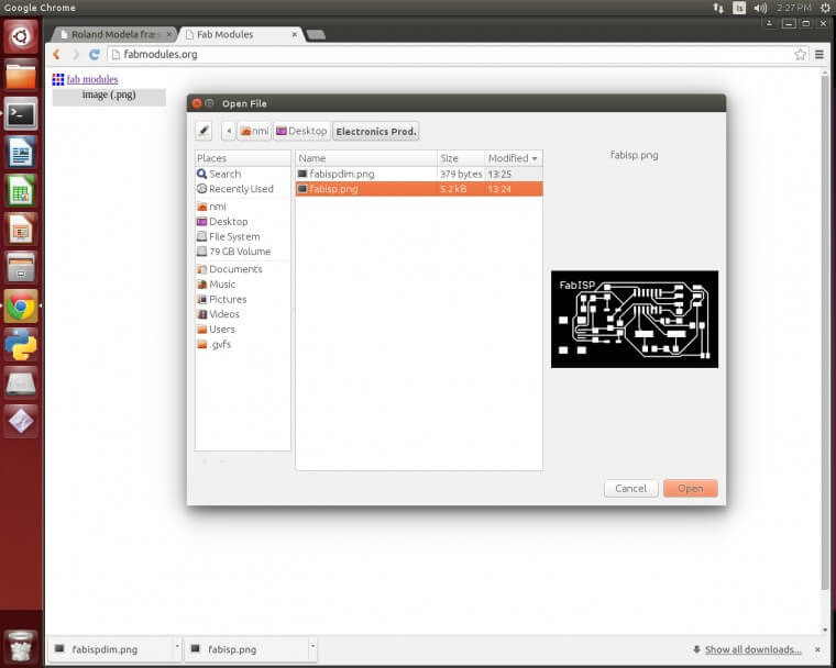
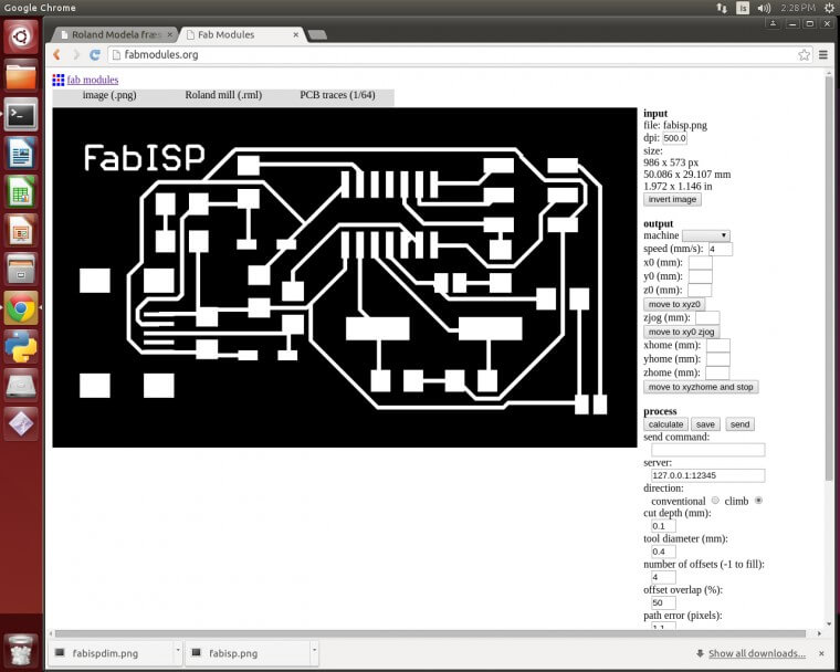
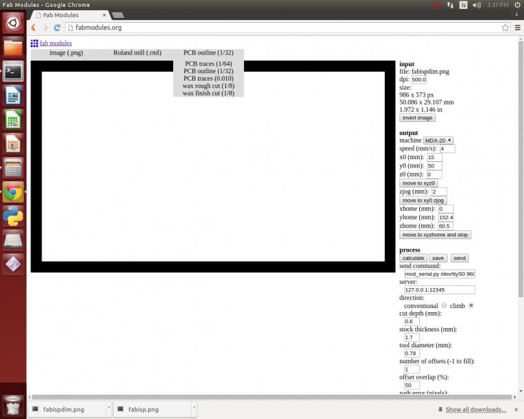
My next step was to go to the Fab Modules on the web, choose png image as the input and select the images i downloaded
The output format is Roland mill (.rml) and for the traces we choose PCB traces (1/64)
The next step was to choose the machine and change the send command text from ttyUSB0 to ttys0. This is necessary to get connection to the port on the computer
I started off by using 0.1 mm in the cut but changed to 0.2 in my second try
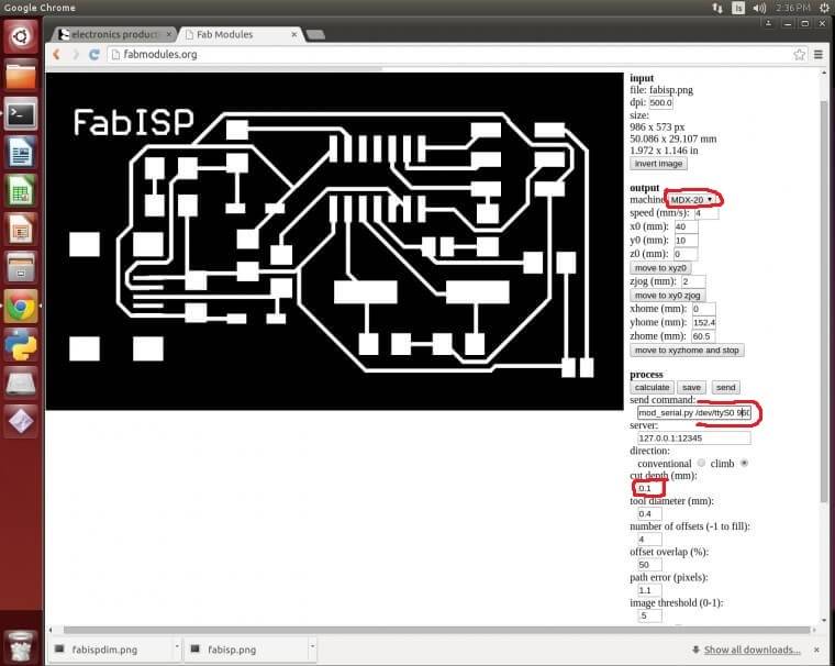
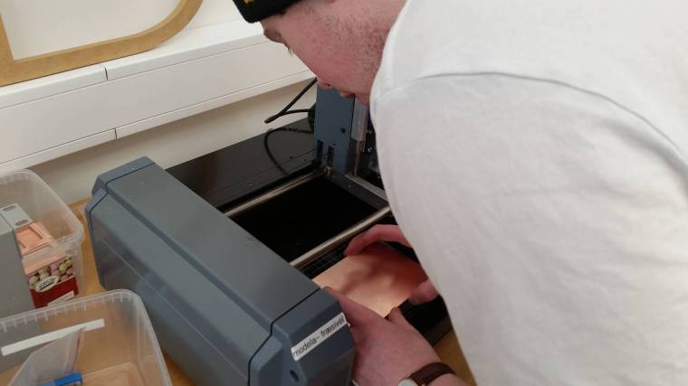
Now i was able to control the machine. I took it out of view mode, changed the end mill and moved it to it´s starting point using the fab modules
I made no more changes other than those i mentioned above, and started the cut
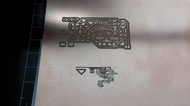
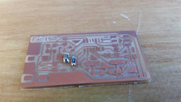
Unfourtunetly my first cutting didn´t go very well.
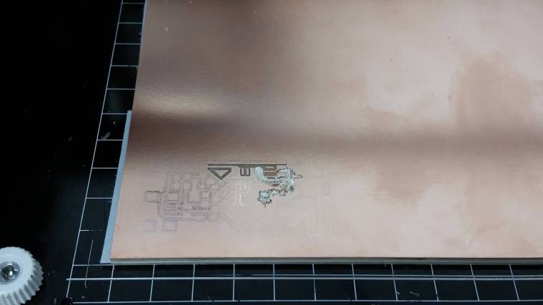
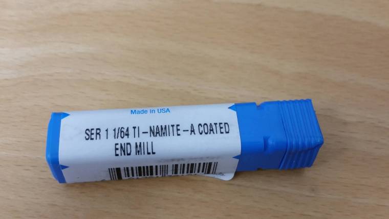
I spotted the problem right away. The end mills we use for the machine are very sensitive and this one had been broken on this board
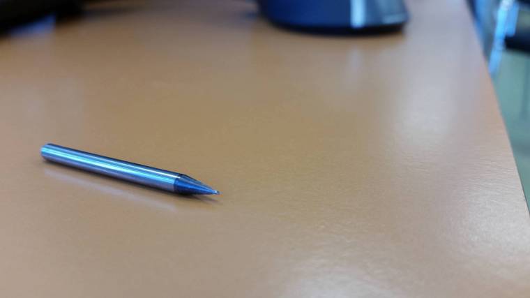
I found another end mill and changed replaced it with the broken one
I also decided to change the cut depth setting from 0.1mm to 0.2mm to be 100% sure the next board would succeed
Here is the difference between the first and second board traces
Next i changed the end mill from 1/64 to 1/32 for the outline cutting,loaded the outline picture and choose PCB(outline) 1/32 in the process option
It was not necessary to change any settings there except from changing the send command text from ttyUSB0 to ttys0
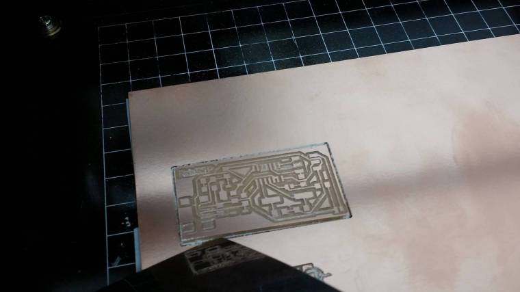
I set the starting point on the same spot as the traces starting point and let the process begin
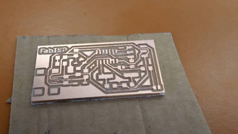
The outlines were successful and i was able to remove my board from the plate
Now my next step was to clean the board and start the soldering
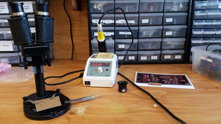
Soldering the board
I did not have much experience with soldering before and was excited to start on this one
I decided to start on the smaller components and in the middle of the board and work my way from that. My plan was to end on the bigger components
I read tips on the Fab Wiki page on how to solder and that helped me alot
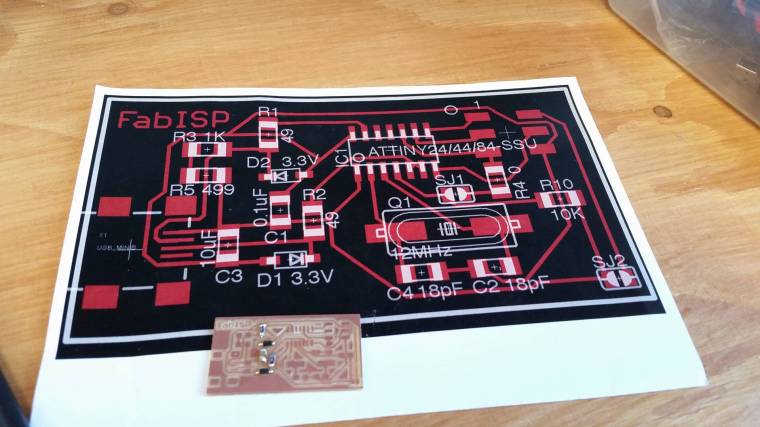
I downloaded the eagle board file and printed it out to see which components to use and where
I thought the soldering went very well, except from few errors surrounding the microcontroller and the Mini Usb
Those two components are the hardest in my opinion to solder, but in the end everything went well
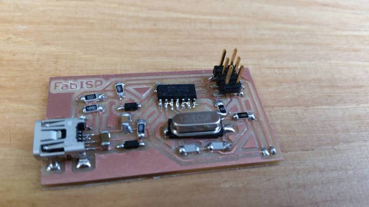
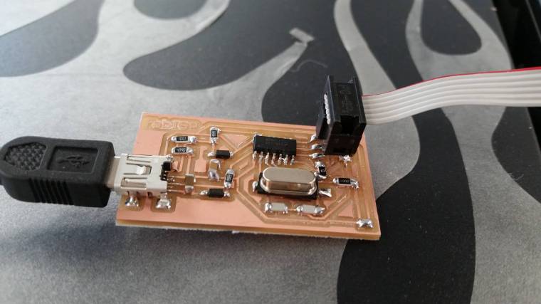
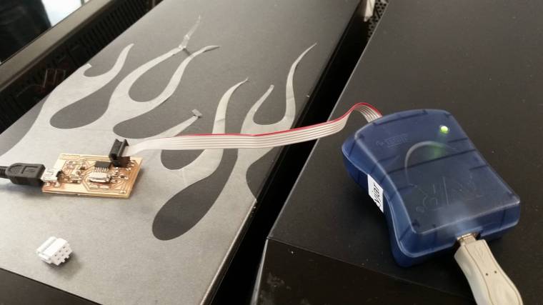
After the soldering was finished i used the AVRISP2 to check if the board was able to connect to the usb drive
Luckily enough it worked on my first try so i look at this week as a succesful one!