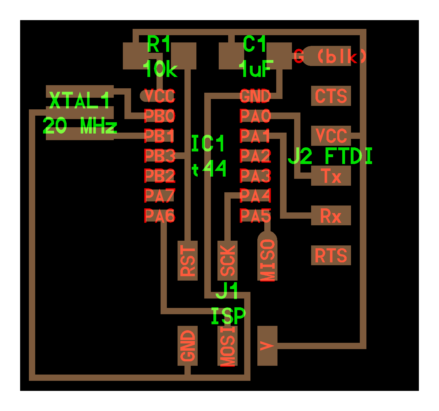
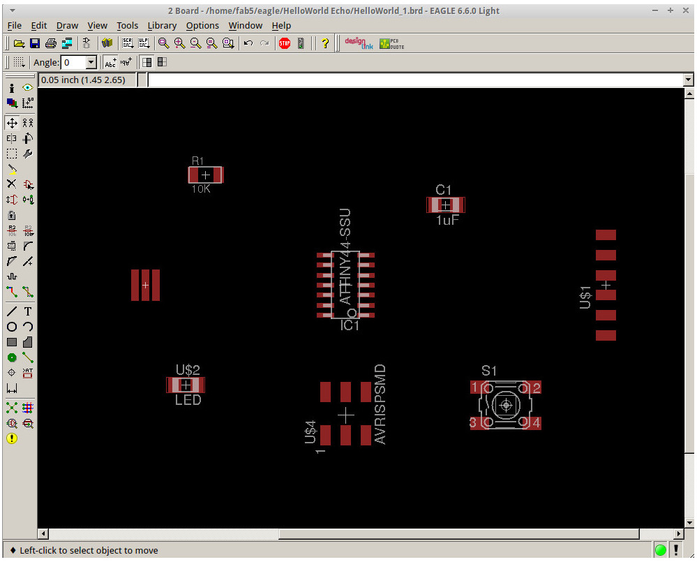
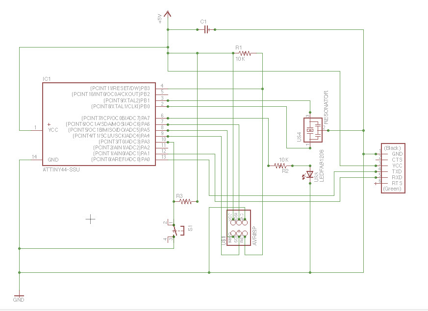
| Element/Part Description | Corresponding Part Name | Library | Quantity Used |
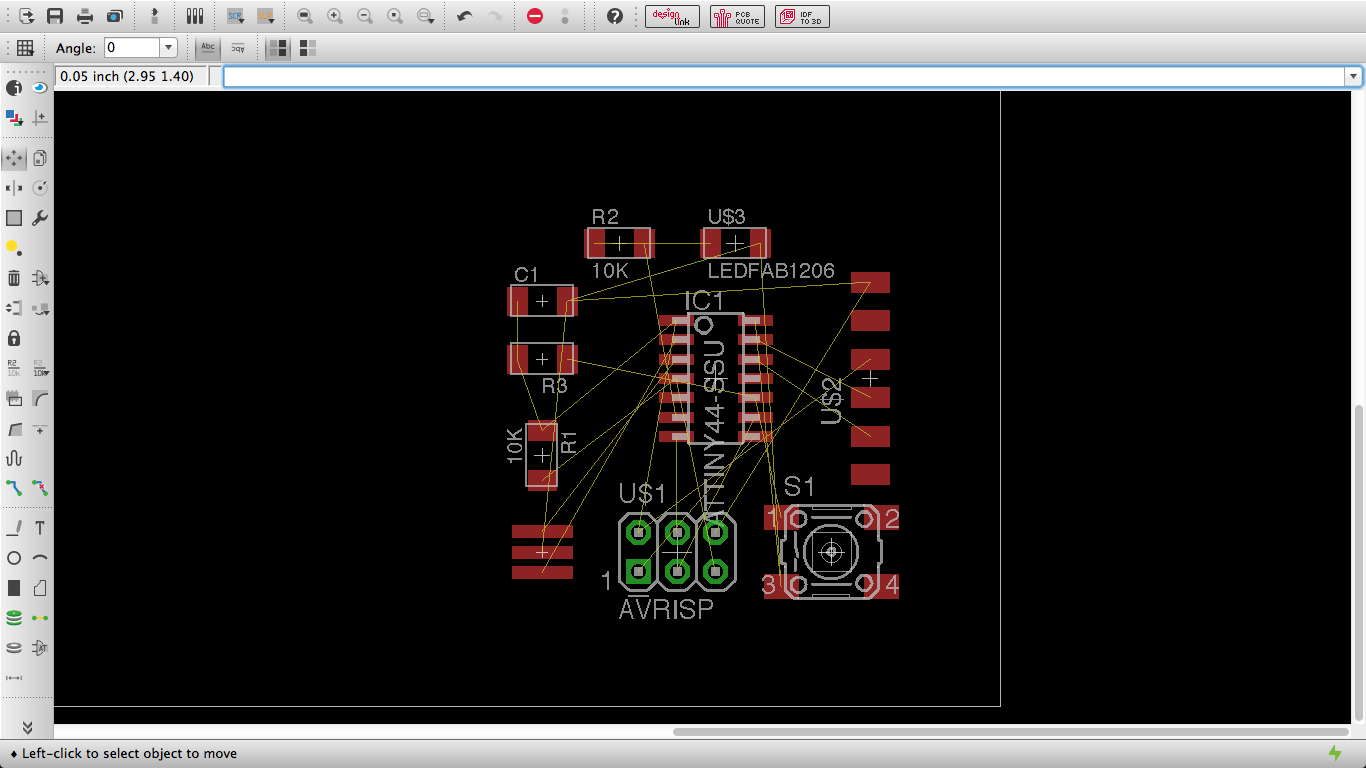
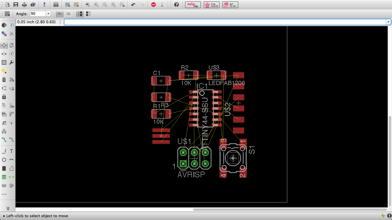
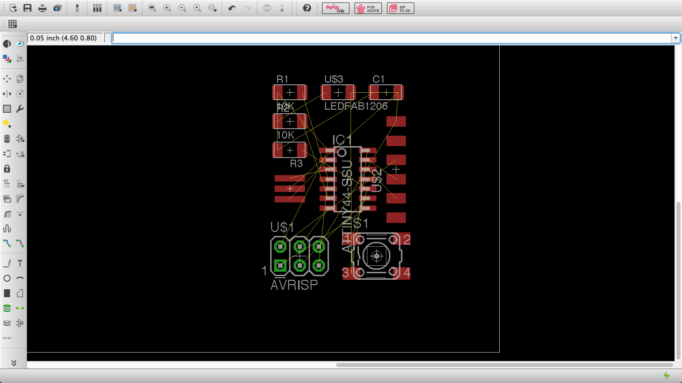
| 10k Resistor | RES-US1206FAB | fab.lbr | 2 |
| 500 ohm Resistor | RES-US1206FAB | fab.lbr | 1 |
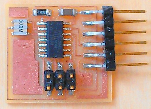
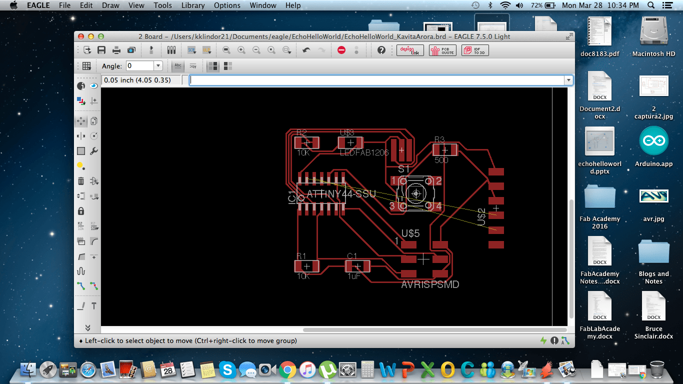
| ATtiny44 IC Package | ATTINY44_SSU | fab.lbr | 1 |
| 1uF Capacitor | CAP_US/CAP_US1206FAB | fab.lbr | 1 |
| 20 MHz (3-pin) Resonator | RESONATOR | fab.lbr | 1 |
| FTDI header pins | FTDI_SMD_HEADER | fab.lbr | 1 |
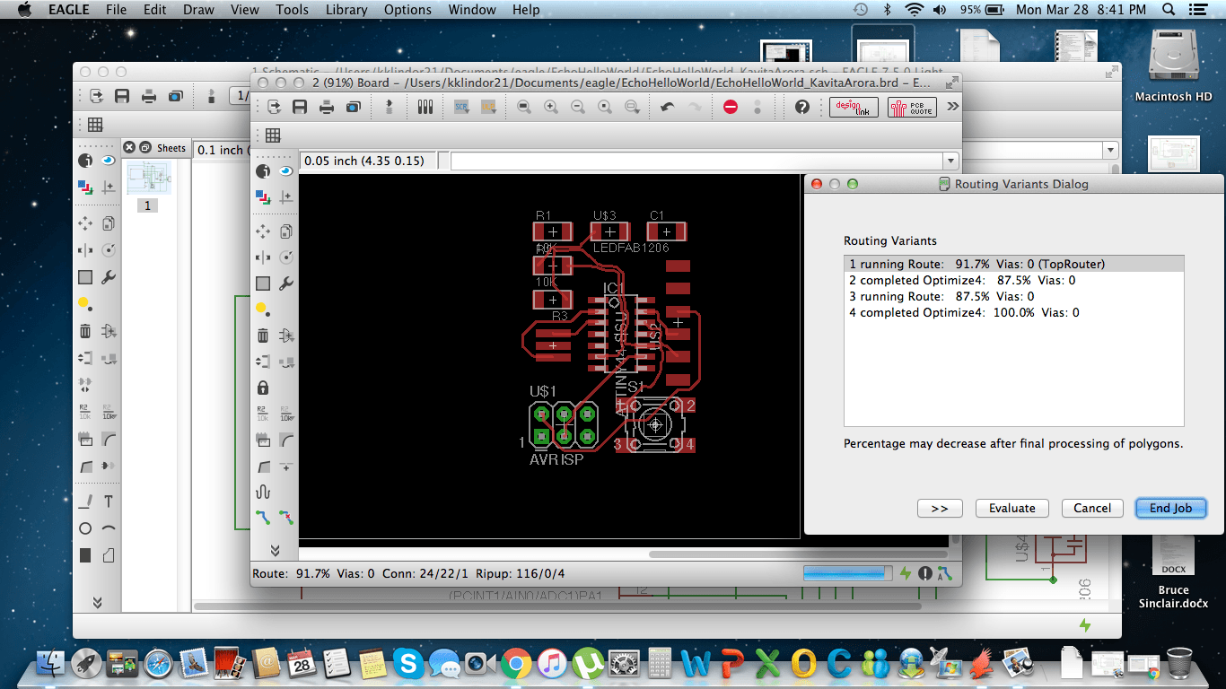
| ISP pins | AVRISPSMD | fab.lbr | 1 |
| LED | led/LEDFAB1206 | fab.lbr | 1 |
| Pushbutton | 6MM_SWITCH6MM_SWITCH (OMRON SWITCH) | fab.lbr | 1 |
| Power Supply (+5V) | Supply1/+5V | Supply1.lbr | 1 |
| Power Supply (GND) | Supply1/GND | Supply1.lbr | 1 |
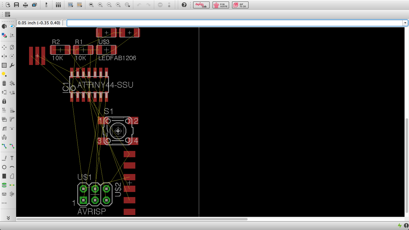
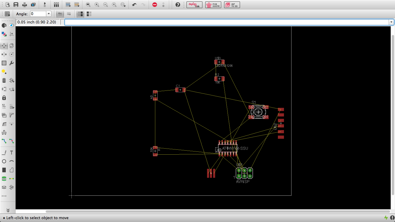


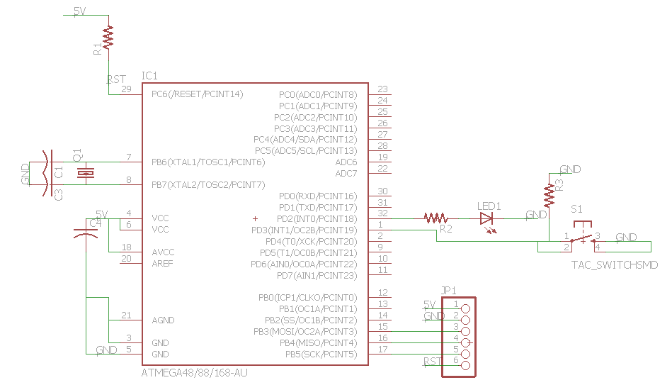
| Element/Part Description | Corresponding Part/Package Name | Library | Quantity Used |
| 10k Resistor | R-US_M0805 (R-US_) | adafruit.lbr | 2 |
| 500 ohm Resistor | R-US_M0805 (R-US_) | adafruit.lbr | 1 |
| ATMEGA48 IC Package | ATMEGA48/88/168-AU | atmega8.lbr | 1 |
| 1uF Capacitor | C-USC0805 (C-US) | adafruit.lbr | 3 |
| 2-pin Crystal | CRYSTALHC49UP (CRYSTAL) | adafruit.lbr | 1 |
| FTDI header pins | PIN HEADER | pinhead.lbr | 1 |
| LED | LEDCHIPLED_1206 (LED) | adafruit.lbr | 1 |
| Pushbutton | TAC_SWITCHSMD (TAC_SWITCH) | Sparkfun-Retired.lbr | 1 |
| Power Supply (+5V) | Supply1/+5V | Supply1.lbr | 1 |
| Power Supply (GND) | Supply1/GND | Supply1.lbr | 1 |