Week 14 Assignment: Design and make a 3D mold (~ft2), and produce a fiber composite part in it
Go back HOME
Composites week was a few levels up from our Molding and Casting week! For my assignment I had to create a machinable 3D model with a minimum of a one square foot area. I realized that unlike my molding and casting assignment, my composites assignment needed some kind of a double curvature element to it, and began to plan to compose such a design accordingly.
Update: May 15th, 2016 -- Initial Ideas and Planning [ABANDONED due to difficulty in implementation]
I finalized on creating a topographical landscape. Originally my plan was to model some kind of cityscape or urbanscape, but due to the pressure of time, I succumbed to creating a simple topographical relief as a means to understand how the fiber composite part would result as it was cast. After all the goal of this week's assignment was to experience composite materials, and my objective was to get a better understanding of the molding and casting process for that very reason!
[OLD UPDATE] Understanding what I wanted to Design
By definition, a Topographic Map is a spatial representation which uses contour lines to show elevation and terrain from a flat perspective. The key idea behind a topographic representation is "relief" which could either be depicted via the use of "shading and casting shadows" (in 2D drawings) or physically constructing an elevation profile in 3 dimensions by carving, chipping and shaping some chuck material.
I had looked at some sample topo relief maps via google:
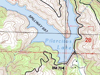
 Topographic Map with Contour Lines [Picture Source]
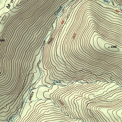
Topographic Shaded Relief Map [Picture Source]
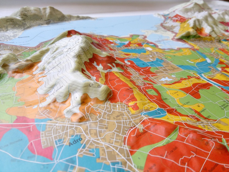
3D (Digital) Raised Relief Map [Picture Source]
Topographic Map with Contour Lines [Picture Source]
Topographic Shaded Relief Map [Picture Source]
3D (Digital) Raised Relief Map [Picture Source]
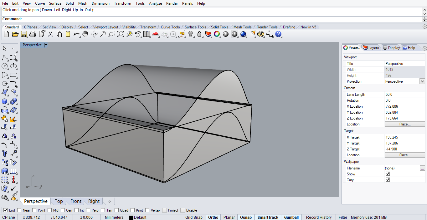
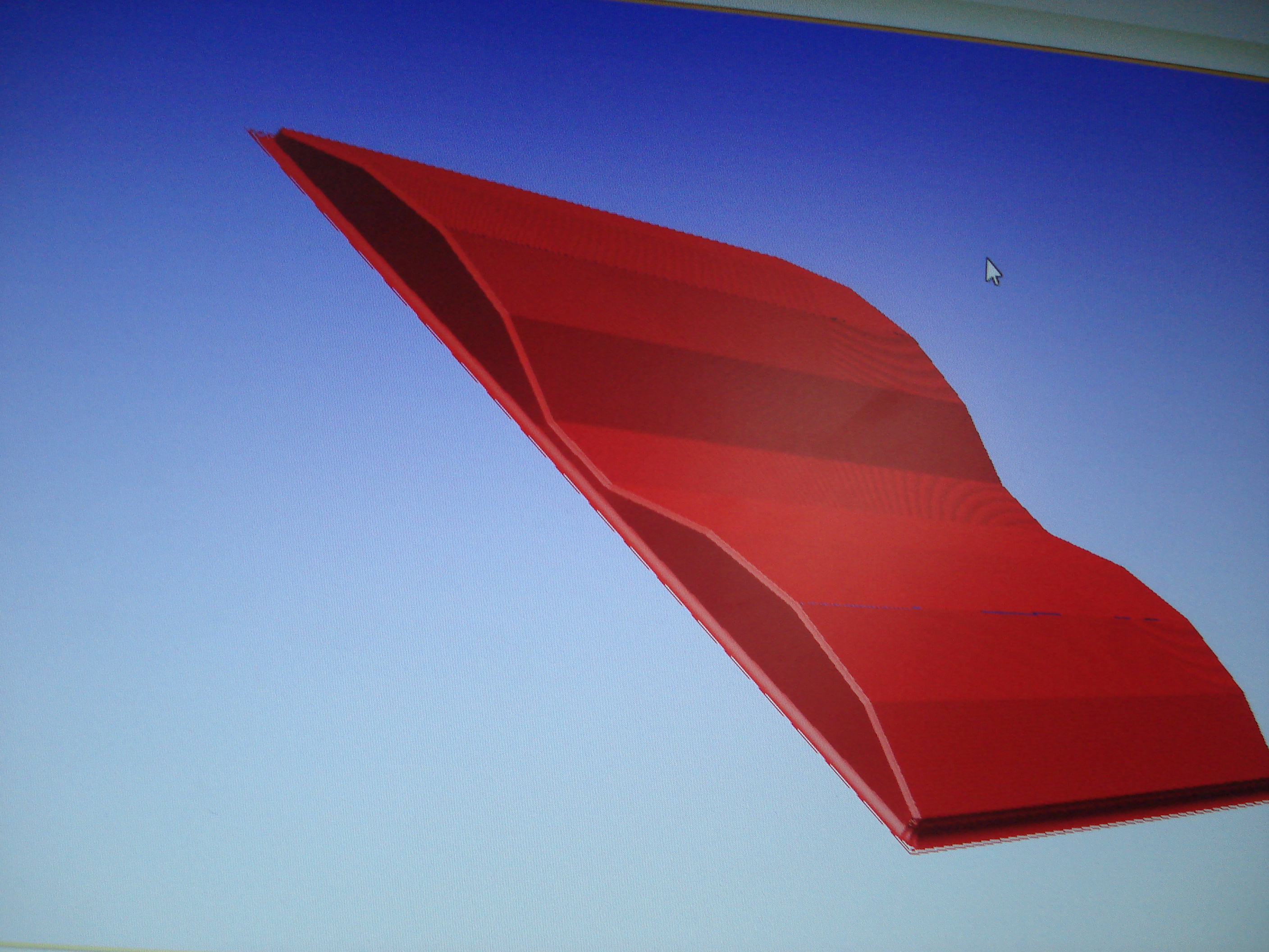
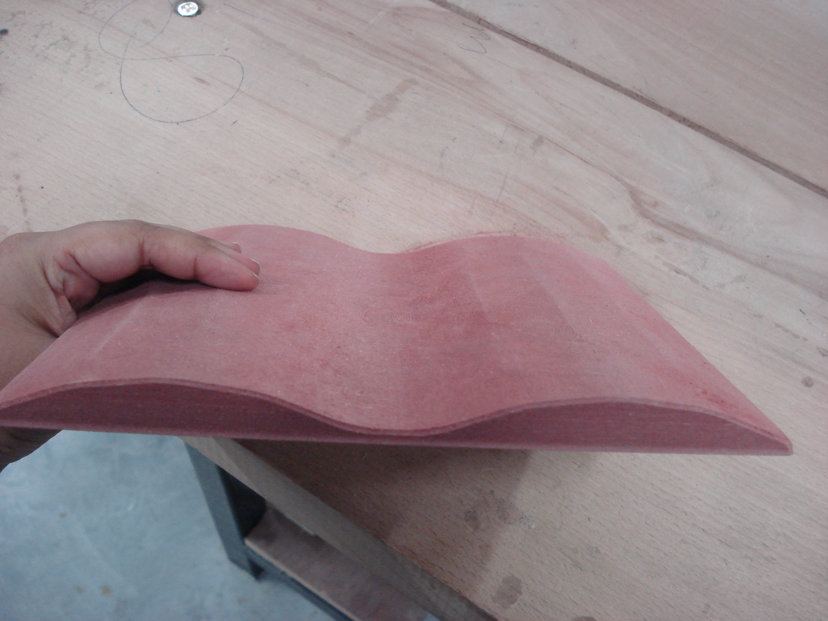
Update: July 7th, 2016 - Creating a simple double curve surface to (plan) a composite fiber cast for
Since I had used Rhinoceros to create prior 3D Models for my other homework assignments, I initially tried to model my double curve project using a combination of Sweep functions. However, at the facility where I had to mill my mould, Rhinoceros software was not an option -- and since I had saved my editable file in Rhino, I had to re-design my model using Pro Engineer - the software they had on their system attached to the CNC mill.
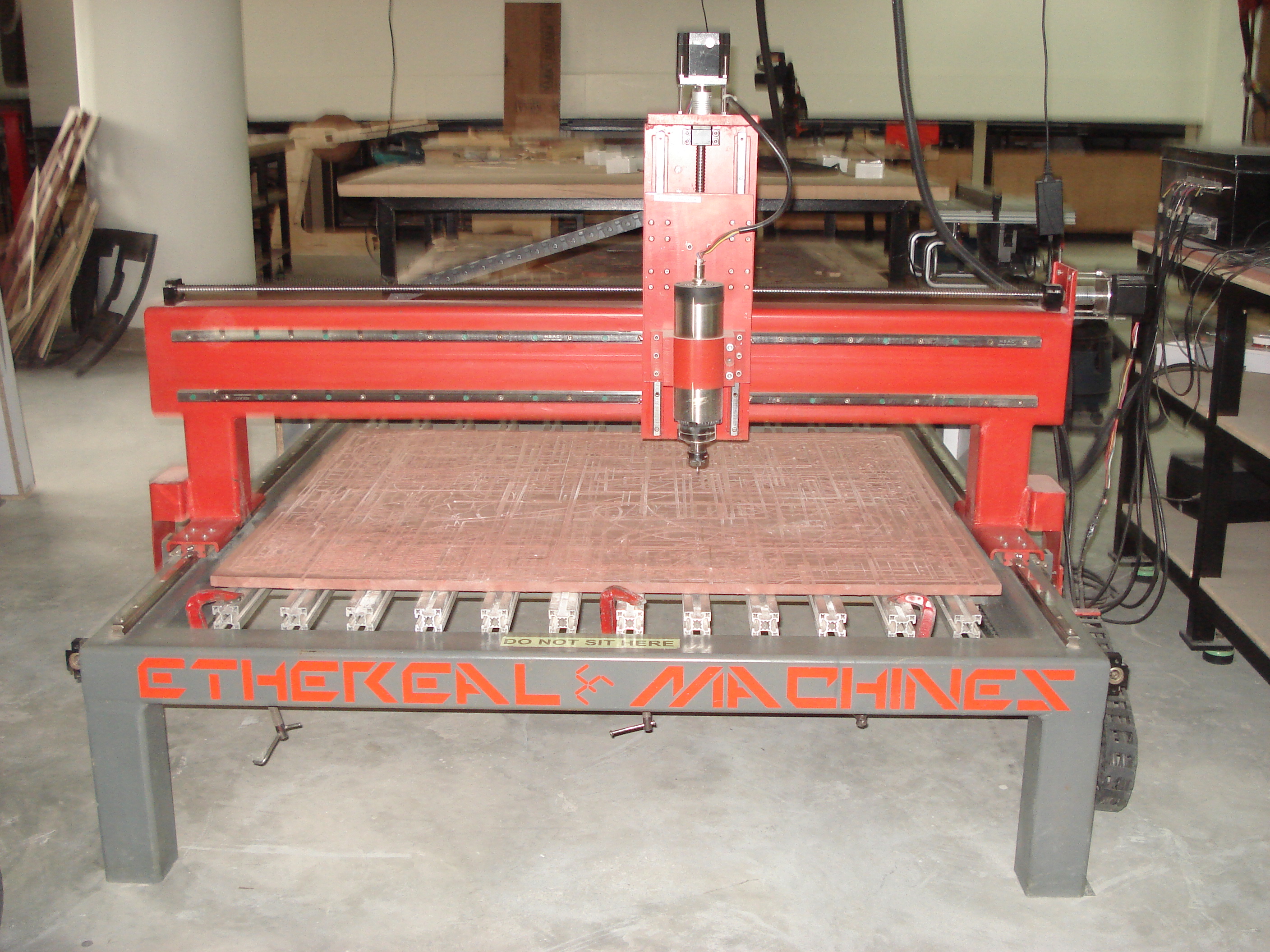
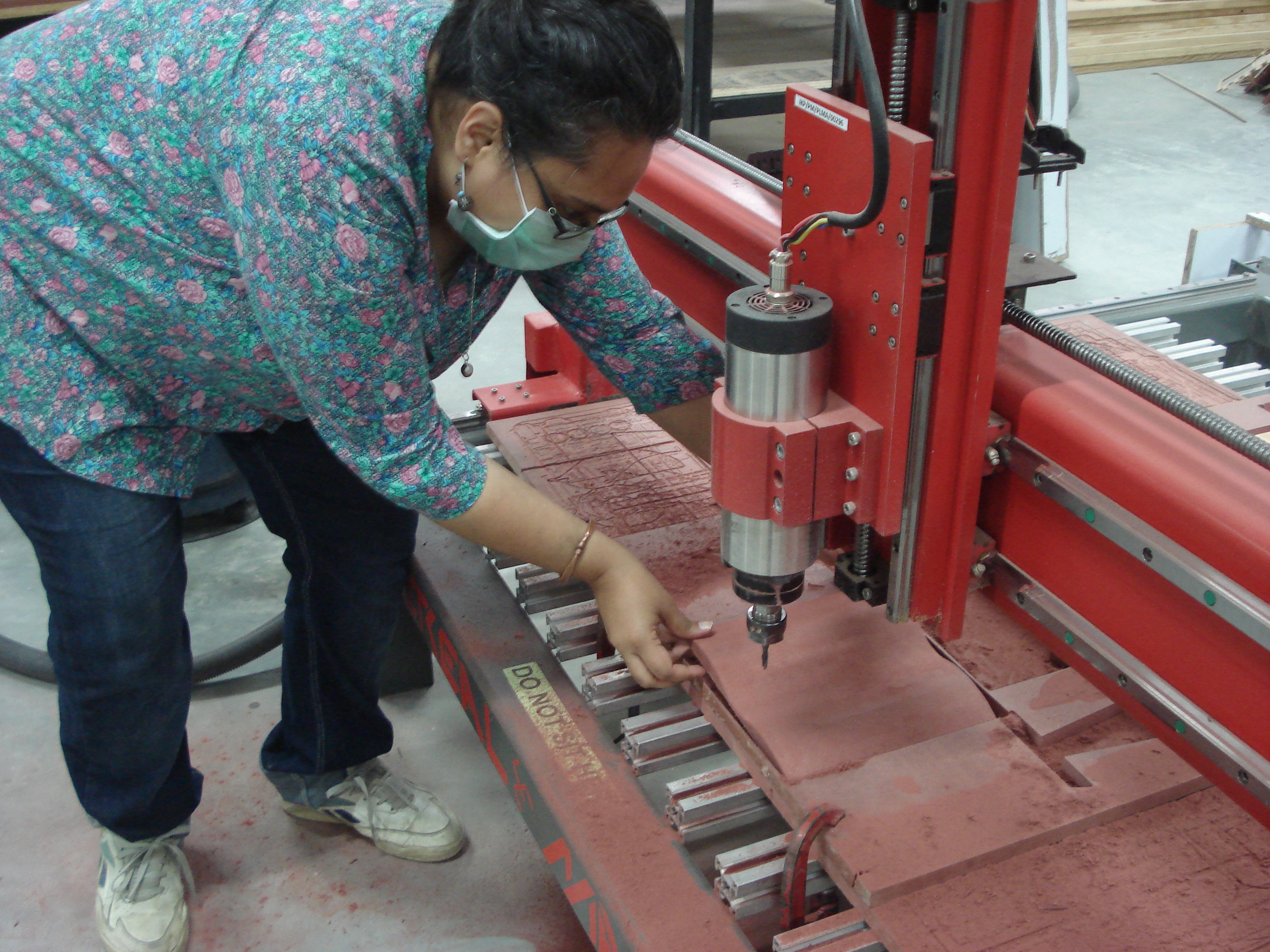
I had to locate a viable CNC machine that could mill my new double curve mold --- luckily I was close to one of Bangalore's largest makerspaces IKP-EDEN -- and I was able to use their equipment to machine my design after having made some adjustments to it upon examining the kind of material I had available to me. I ended up milling a 22cm x 22cm piece of 17mm MDF (wood) [220mm x 220mm x 17mm] on an Ethereal Machines 3ft x 2ft "Ethereal Compact" large format CNC mill.
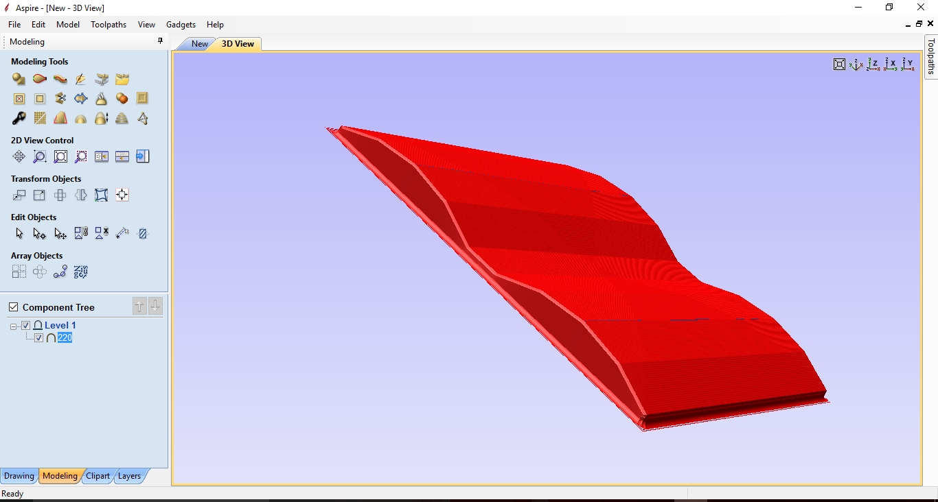
With assistance from the Lab tech at the Makerspace, I exported the Pro Engineer CAD file depicting the double curve projection I had composed -- into the Aspire CAM software program where it was possible to simulate the milling/routing of the double curve structure:
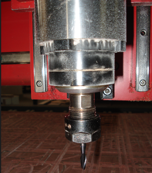
The following settings and inputs were used in the milling process:
- 6mm Ball Nose End Mill
- Spindle Speed: 18000 RPM
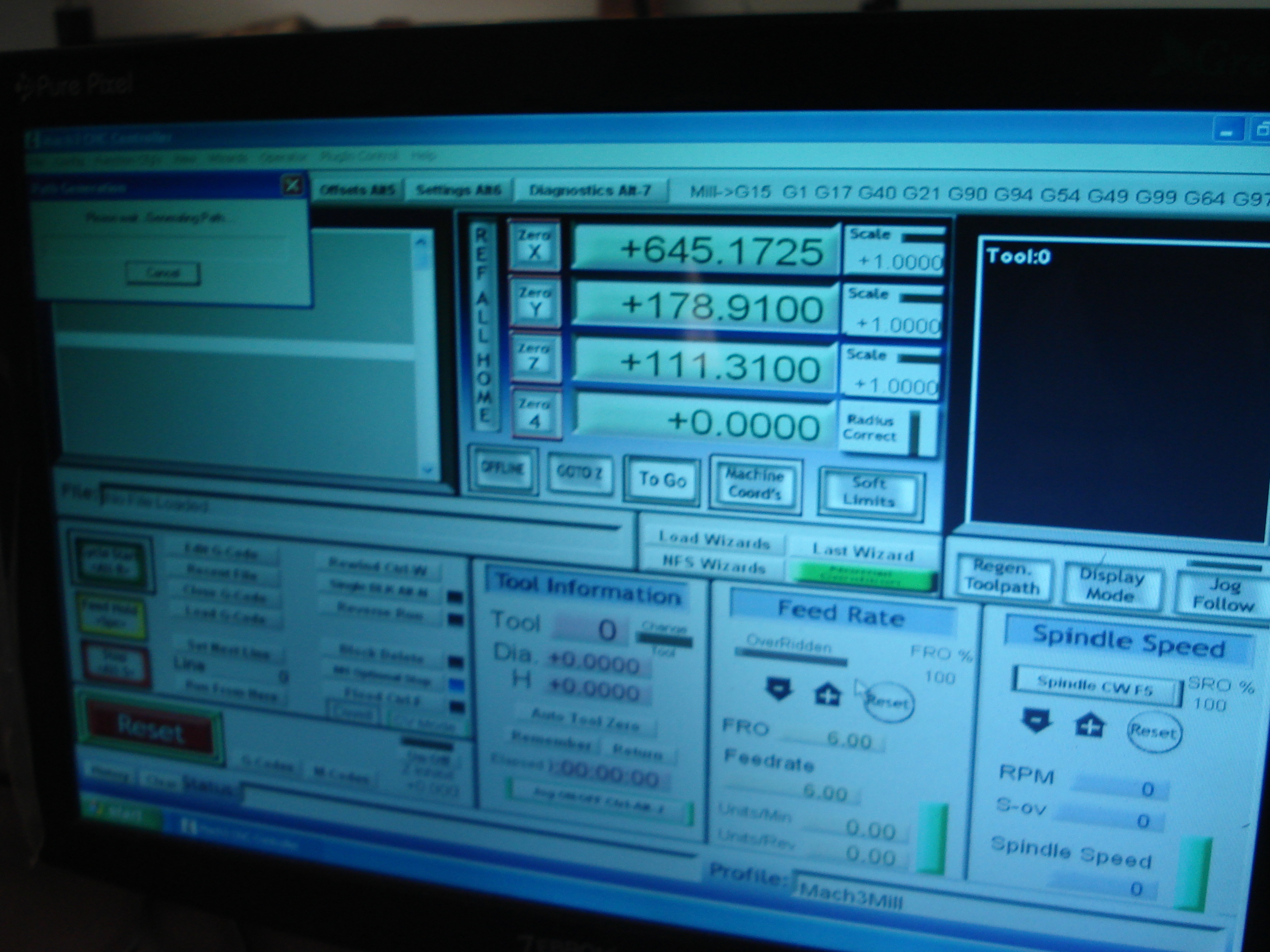
- G-Code generator software: Mach3 Controller
- Total time taken for Job: 2.35 hours
- Please find the files used for Milling this Double Curve shape: STL | G-Code Toolpath
Note: I am still in progress of procuring materials for my fibre cast. I am working on creating the cast I had planned on creating when I started this assignment (the fibre cast for the double curve project)
ASSIGNMENT UPDATE is STILL IN PROGRESS!
Go back HOME