Week 11 Assignment: Measure something - add a sensor to a microcontroller board that you have designed and read it
Go back HOME
Input Devices was an exciting week of trying and testing several kinds of sensors with microcontroller boards we had fabbed.
Although our assignment was to measure input received from a sensor attached to a microcontroller we had "designed" -- I was curious to explore the "measurement" aspect of Input Devices which were discussed during Week 11's Lecture.
1st Exercise: Debouncing the input from a Switch
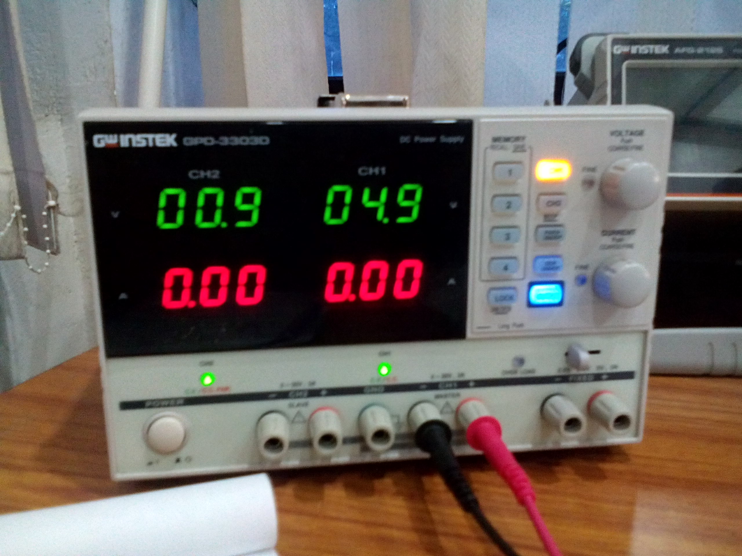
Since our remote guru had asked us to understand the properties of what it meant when "bouncing" occured during an input event, I went about analyzing the signal that arose when a button was clicked. I used a regular tactile push button (through hole component) and hooked up the power and ground oscilloscope leads to the relevant sections of the button, having set a 5V DC voltage (via the bench top power supply in our lab) across the switch in question:
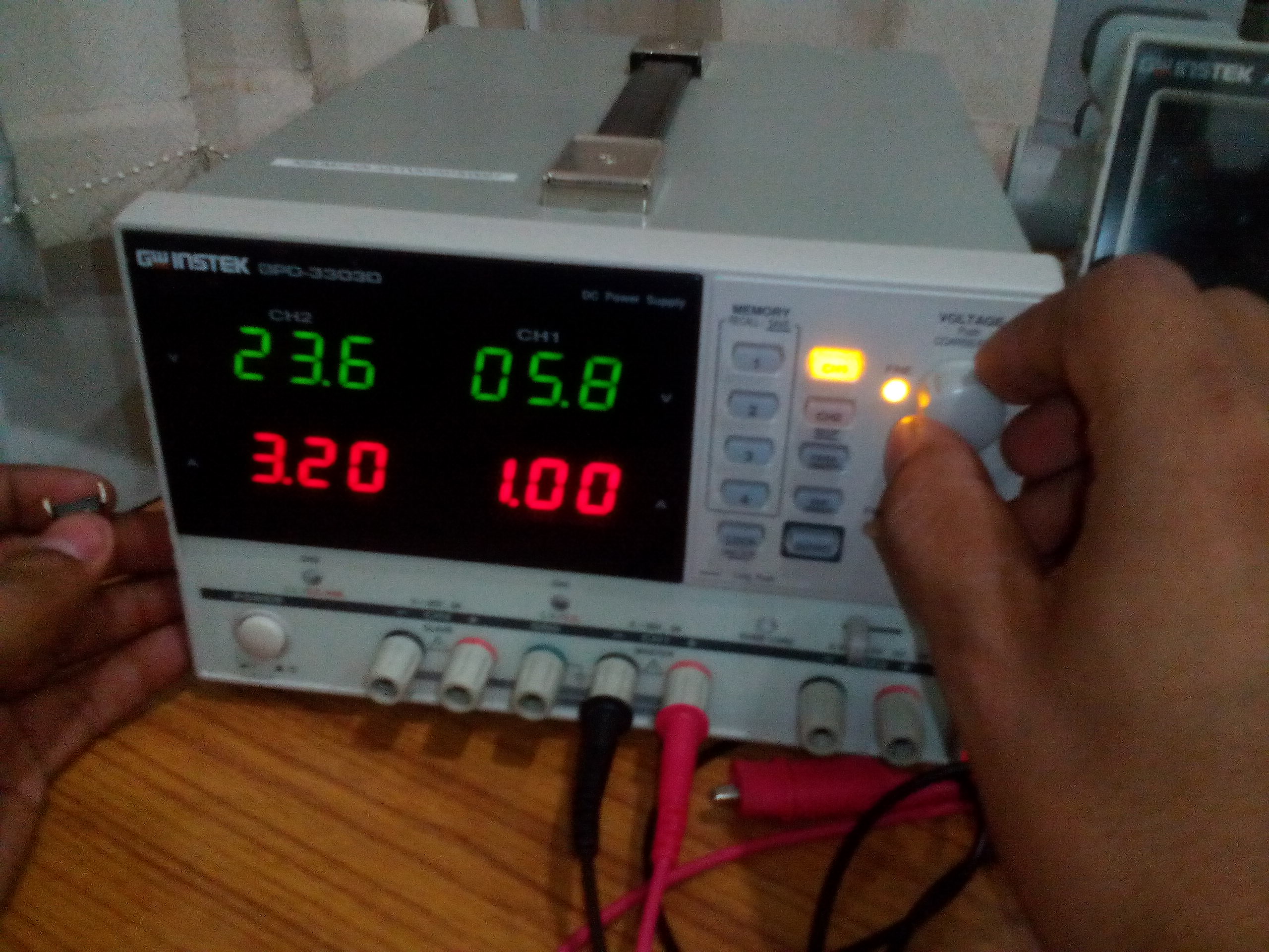
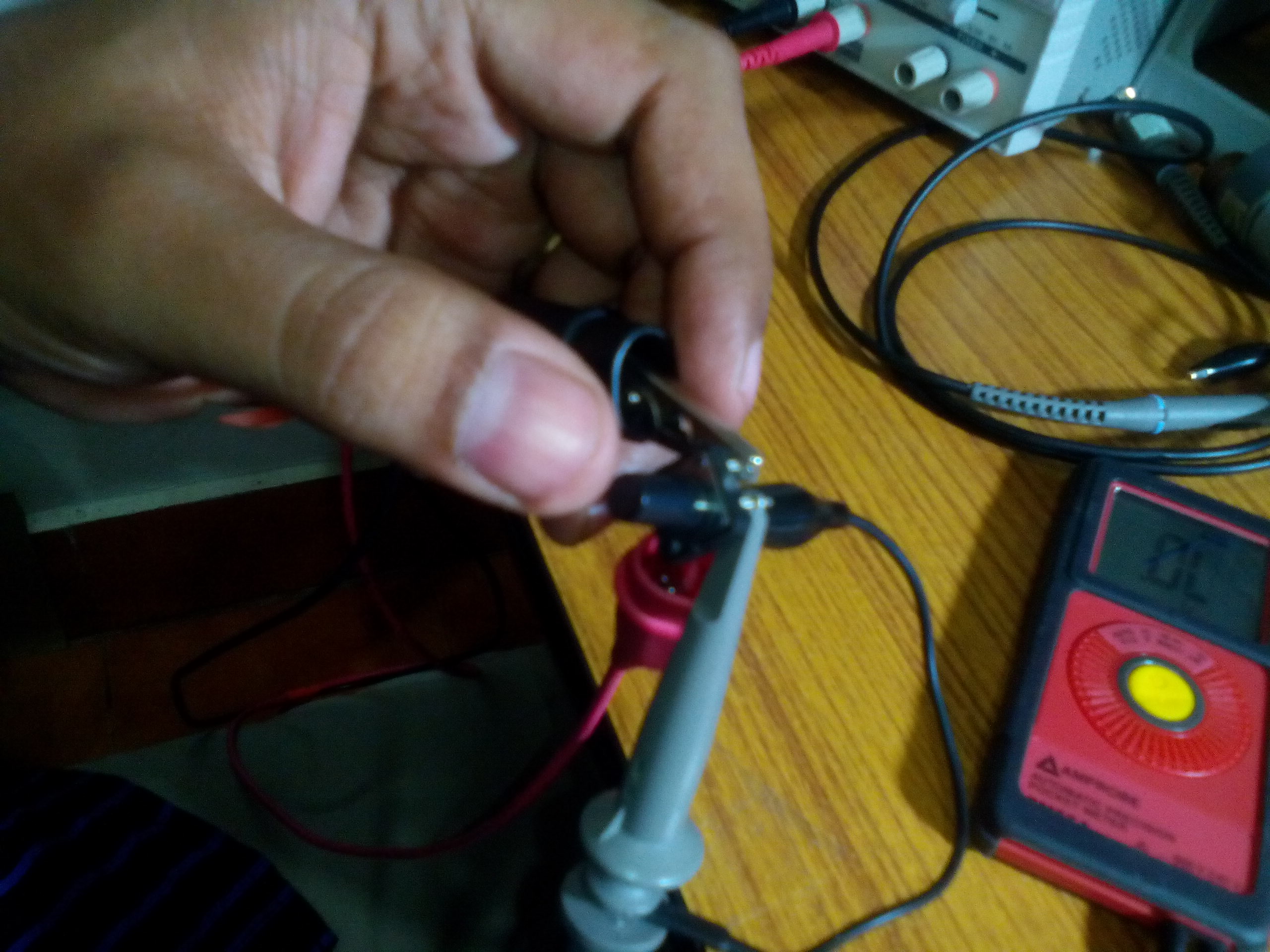
Set up of a 5V DC Voltage signal on the Power Supply Connecting the various leads to the Tactile Button Switch
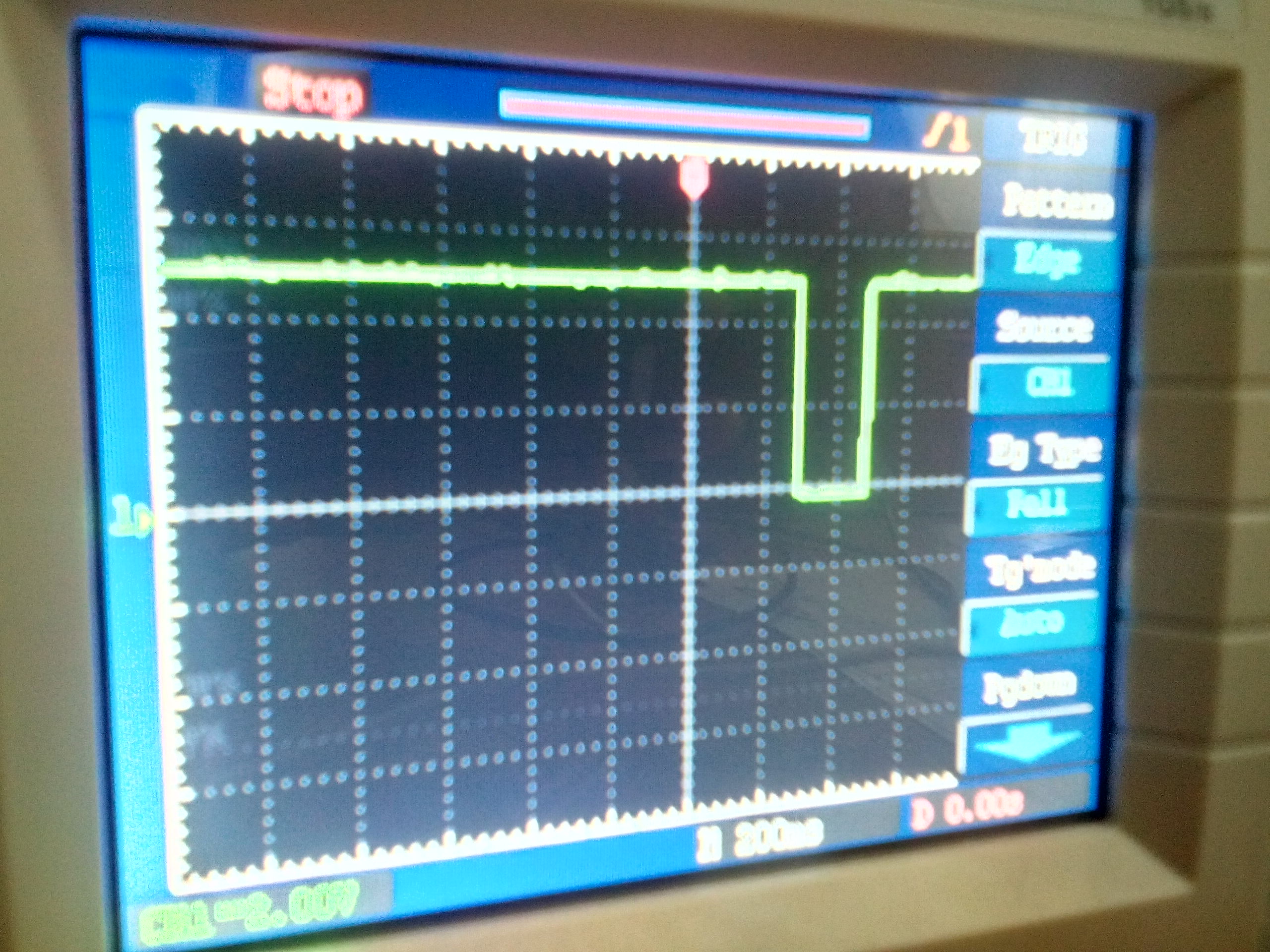
Before the button was pushed the signal trace observed on the Oscilloscope was the standard 5V DC voltage. During the button push, a disturbance was seen in the waveform - which was expected, since an "event had been triggered" -- however, noticing the "non-smooth edges" in the event trigger/disturbance -- it was observed that "bouncing" was occurring during the button press. [Note: One can't see the 'non-smooth' edge of the event trigger in the picture below, but it's there :)]
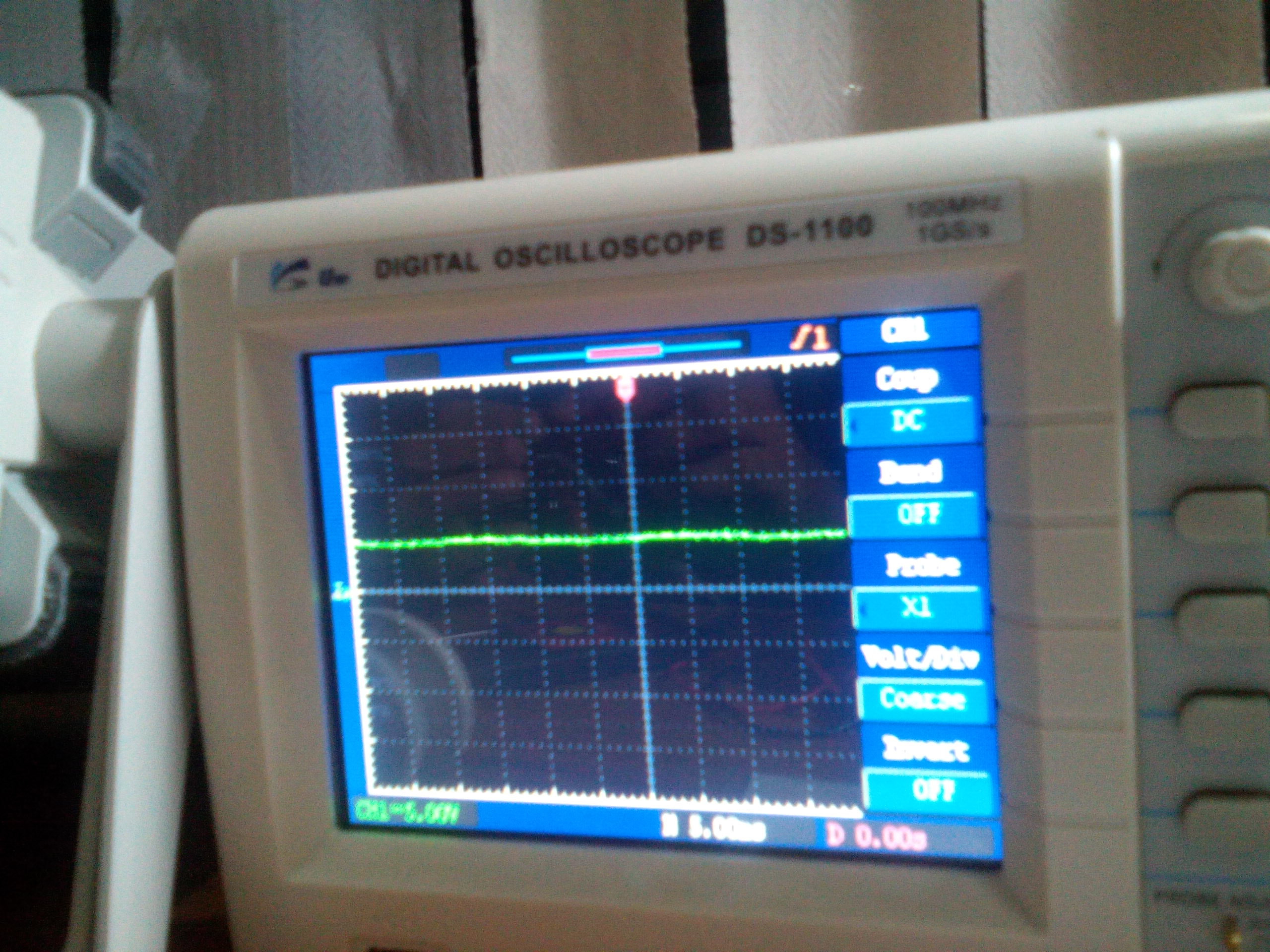
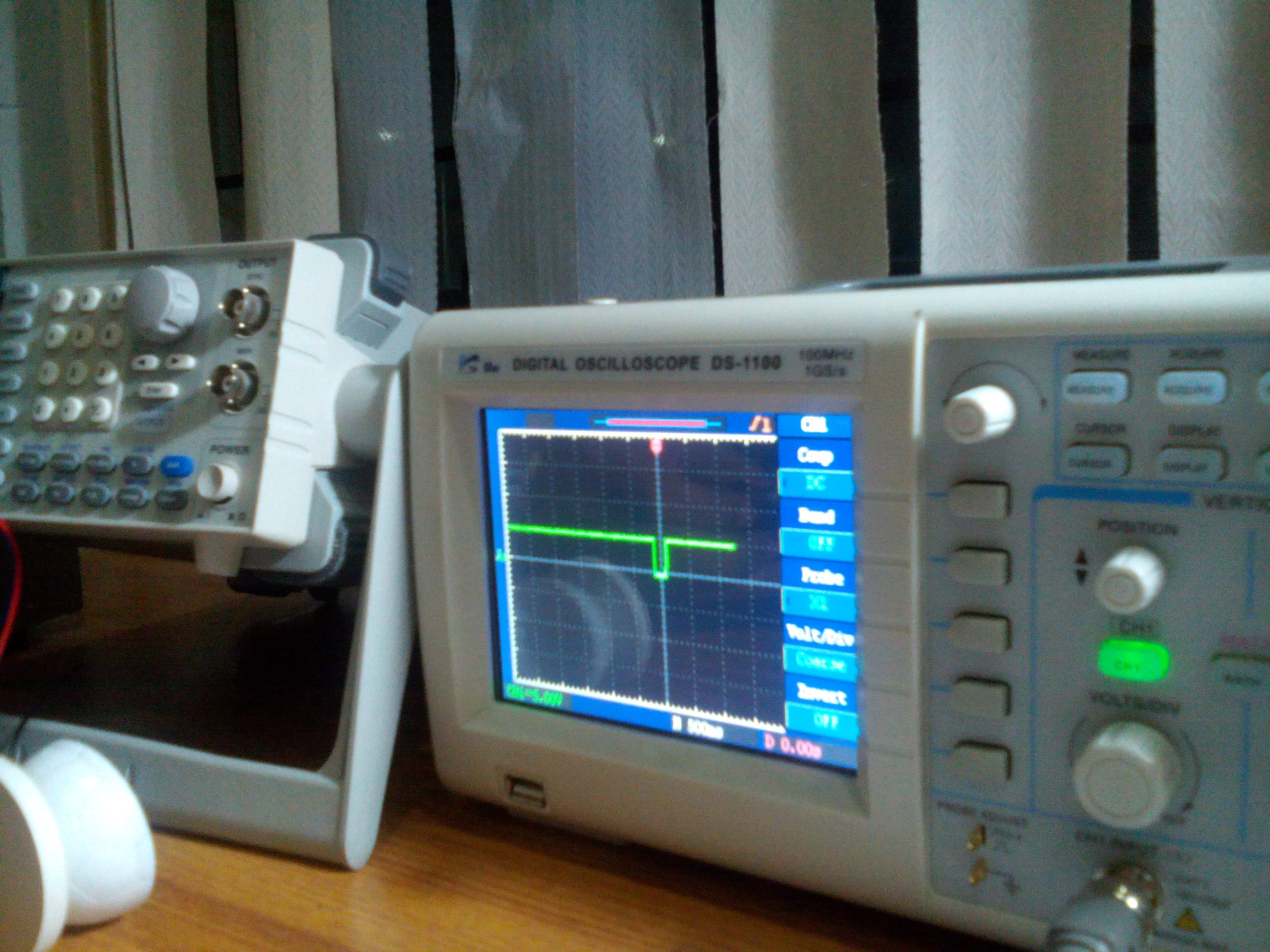
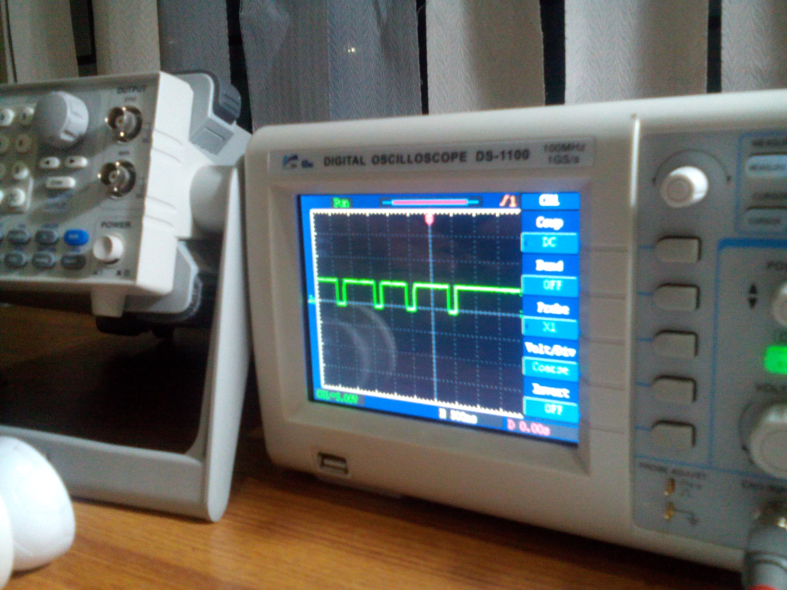
Waveform before the Button Press Waveform capturing the Button Press event Multiple Button Presses
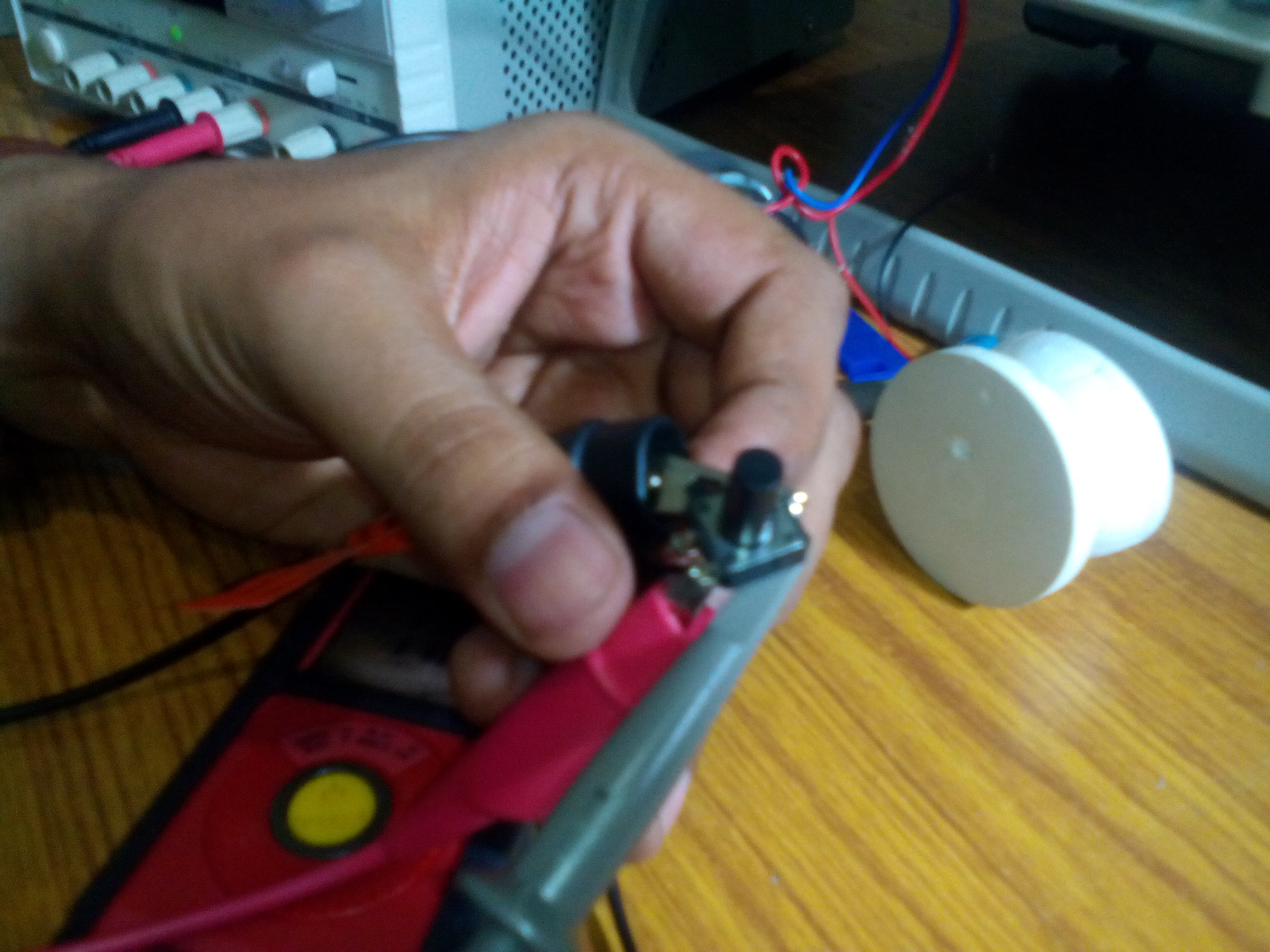
In order to "smooth-out" the button press/event trigger - I connected a 10nF non-polarized (ceramic) Capacitor to see if I could successfully de-bounce the signal:
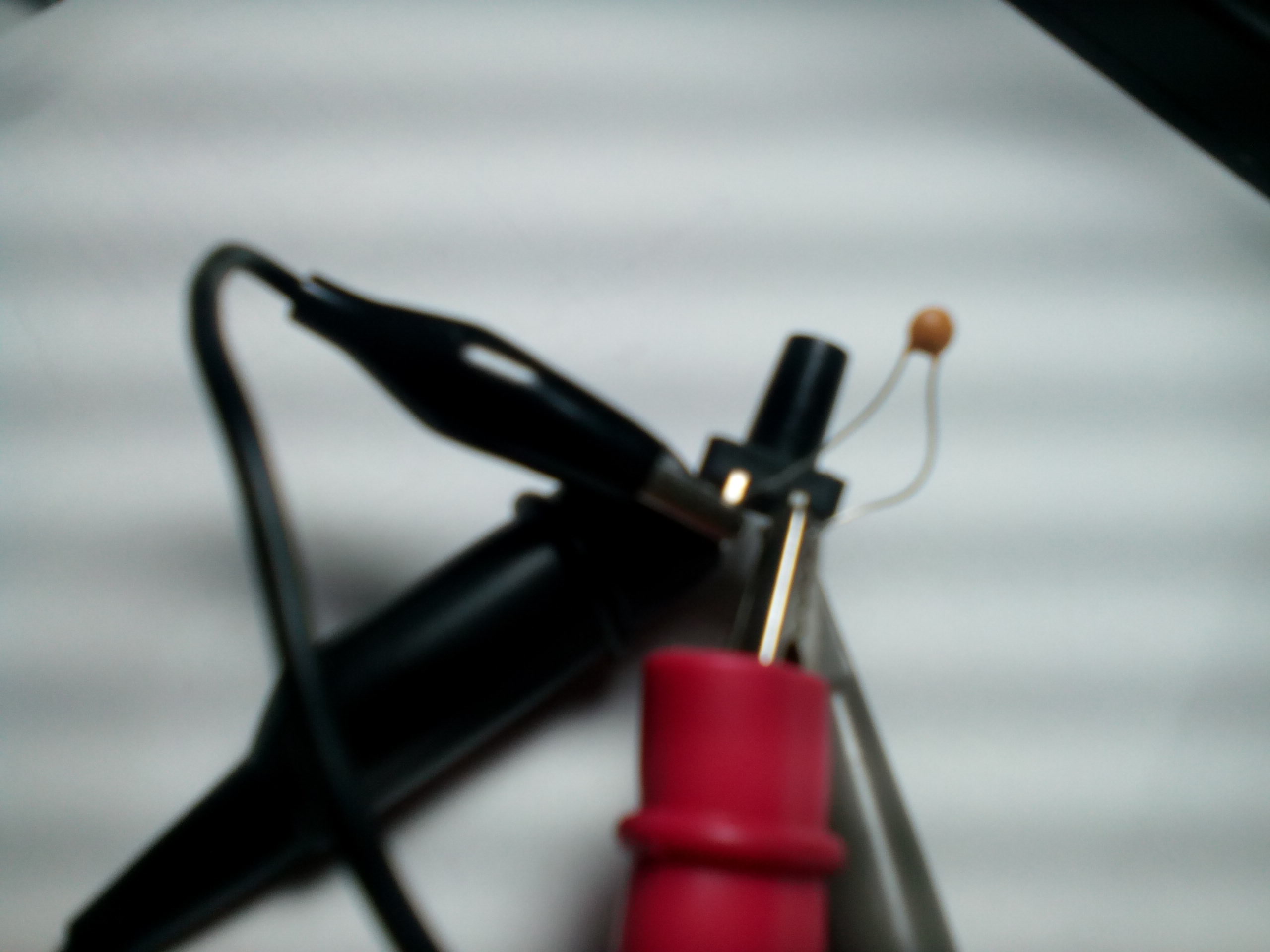
Connecting a 10nF capacitor to push button Supplying a 5V DC voltage across the button + capacitor Smooth Edge observed on waveform during Button Press
My next plan of action was to get a better idea of what kinds of sensors existed and how they could be interfaced with microcontroller platforms. I tried a bunch of different sensors using an Arduino UNO with the Arduino IDE.
2nd Exercise: Reading [analog] input from a Light Dependent Resistor (LDR)
** Please find my Source Code used to compile the Analog Input from the LDR: AnalogInSerialOut_1stTest
Components Used:
- Arduino UNO R3 board
- Light Dependent Resistor (LDR)
- 220 ohm resistor
- Jumper Wires + USB A-B cable
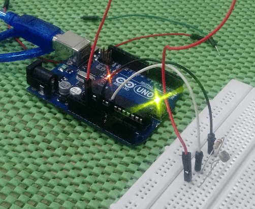
Connecting an LDR (sensor to detect light) to Arduino Reading Analog Input from LDR as displayed via the Serial Console
Major Learnings:
An LDR takes in Analog Input in the form of light intensity - since it's a resistor at its core, the amount of light it gets from its surroundings varies the amount of resistance applied. In the Serial console window of the Arduino IDE, the less the light applied over the LDR, the higher the resistance, and therefore the lower the output values.
3rd Exercise: Reading [digital] input from a Temperature and Humidity (DHT11) Sensor
Components Used:
- Arduino UNO R3 board
- Temperature + Humidity (DHT11) Sensor
- 220 ohm resistor
- Jumper Wires + USB A-B cable
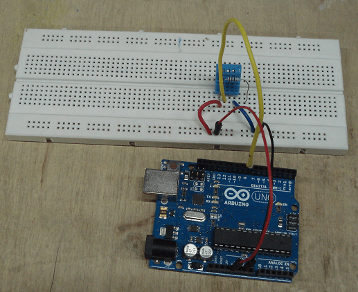
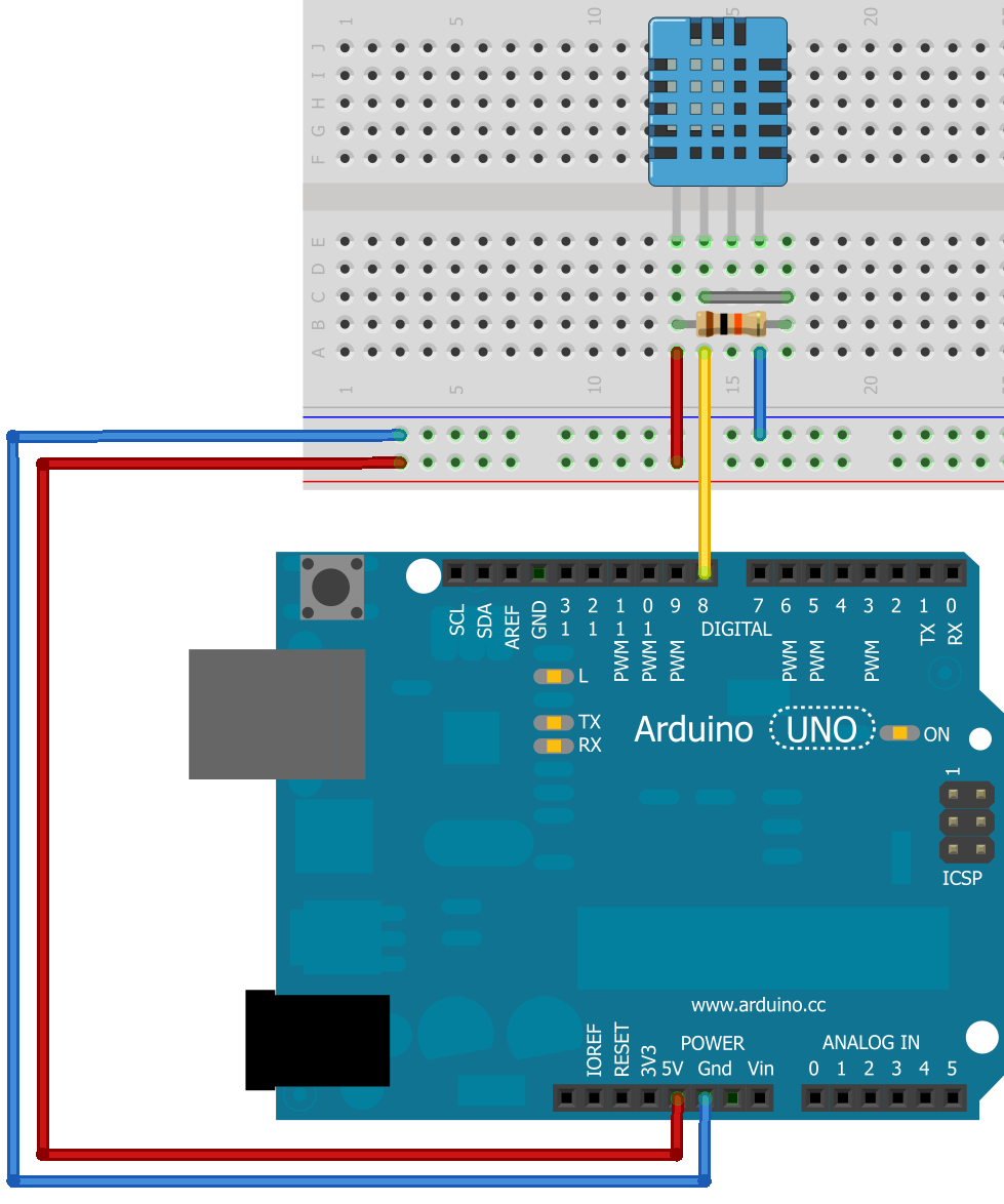
Connecting a DHT11 sensor (to detect Temperature and Humidity) to Arduino Reading Digital Input from DHT11 as displayed via the Serial Console
Major Learnings:
The DHT11 sensor takes in temperature and humidity readings which it converts to Digital Input. This digital input is taken in and directly displayed in the serial console window via the Arduino IDE.
Adding a Sensor to a microcontroller board I had designed -- The Real Input Device :)
Since the actual task of this week was to create an input device from scratch -- I tried this in two ways:
1st Approach: Using an ATMEGA328 DIP package as microcontroller with a Pressure Sensor
2nd Approach: Designing an SMD PCB containing an ATMEGA8 microcontroller with an LDR
1st Approach: Force (Pressure) Sensor Input Device
Components Used:
- ATMEGA328 28-PIN IC (DIP PACKAGE)
- Round Force Sensing Resistor (FSR402) [Sensor]
- Two 10K ohm resistors
- Two 22uF ceramic capacitors
- 16MHz Crystal Oscillator
- Single strand wires, multiple
- [optional] Bar LED component SHB10R (only used to display sensor input)
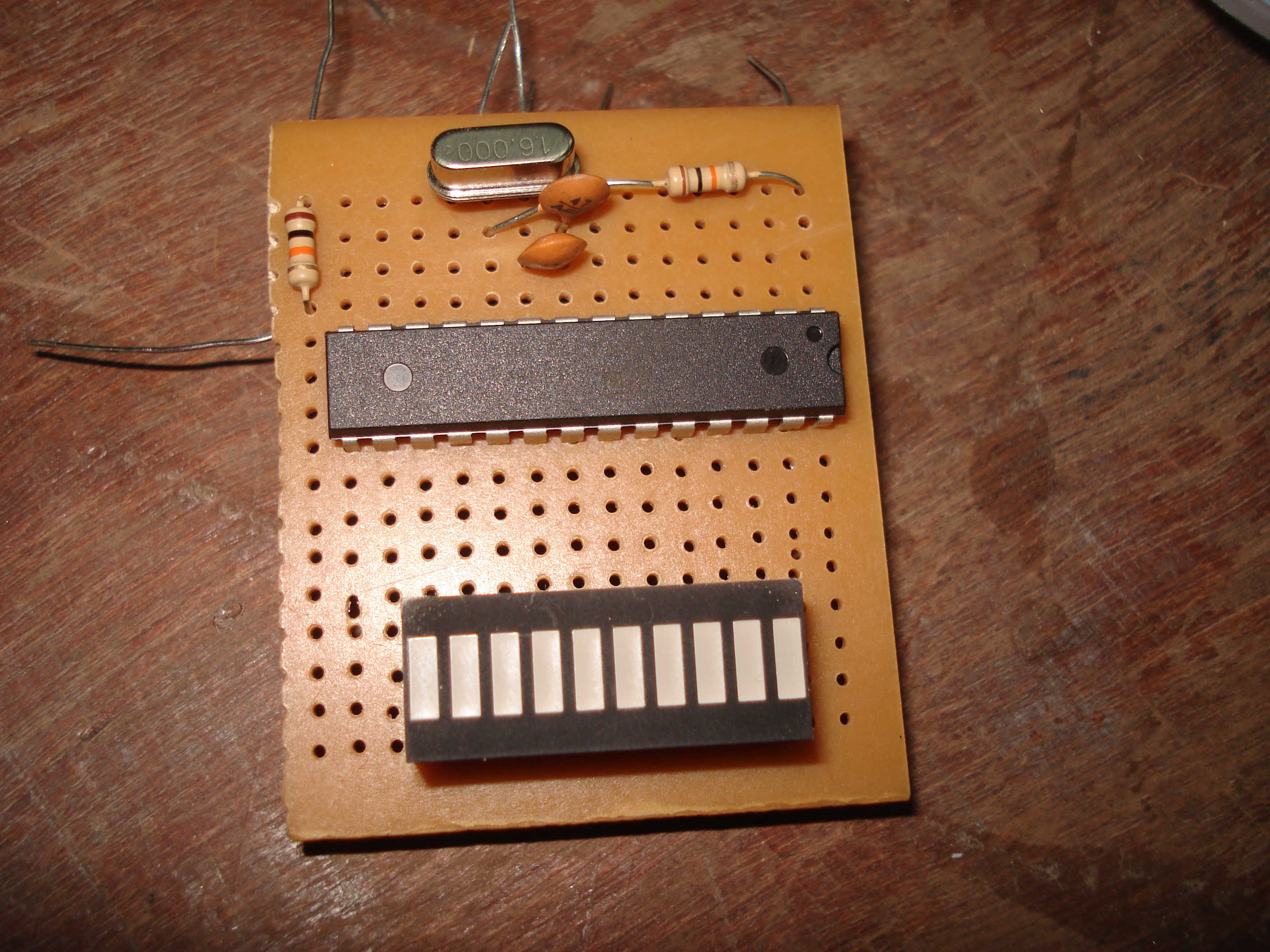
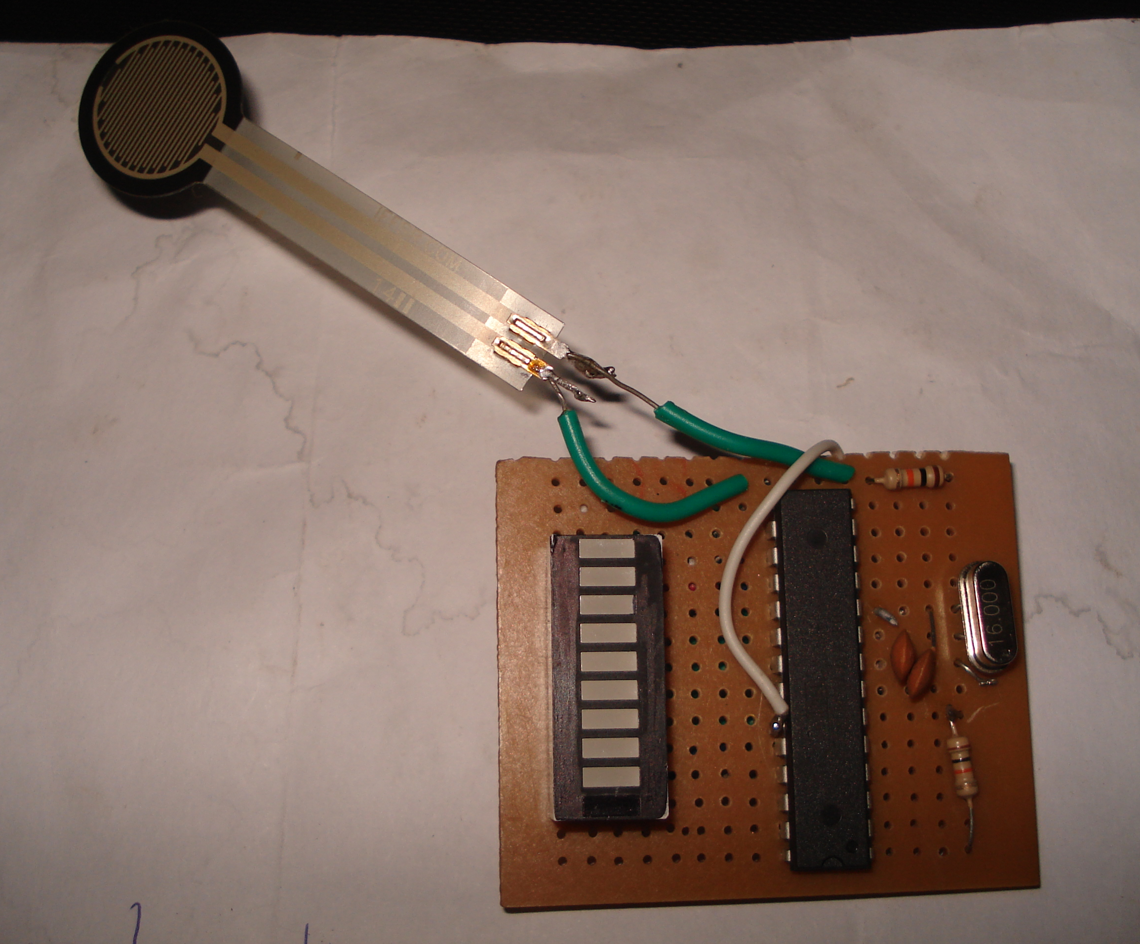

Creating my first Input Device: ATMEGA328 chip with Force sensing resistor input I had added an optional Bar LED graph to depict force-sensitivity readings
Notes: I had initially conceived that I would submit this through-hole component Input Device as my final handin for Assignment 11. However my remote guru reminded me that I had to "digitally fabricate" any input devices I wanted to consider having graded! So I set about doing just that. Please read below.
2nd Approach: LDR-based Sensor Input Device
Components Used:
- ATMEGA8 36-PIN IC (SMD PACKAGE)
- Light Dependent Resistor (LDR) [Sensor]
- [?] ohm resistors
- [something else here]
- [something else here]
The digitally fabricated input device This took a lot longer than I had planned
Notes: Assignment updates are not complete. I ran out of time before I could upload my handin, before the repo closed forever.
Go back HOME