Week 19 : project development
project concept
I am so lazy about cleaning my room, and it is difficult one apart from me. I think youth are facing most difficult problem is cleaning when they are staying out of their own home, me also…in this era every market has available the cleaning machine but they are high costly, or some machines are not 100%, that is why I think a plan to make an automatic cleaning robot for my final project.
features of the cleaning bot
-
It is an Automatic cleaning bot
-
It automatically moves around the room
-
It can avoid obstacle on its path
-
It is portable because it is a compact structure
-
It can easily clean every nook and corner of the room
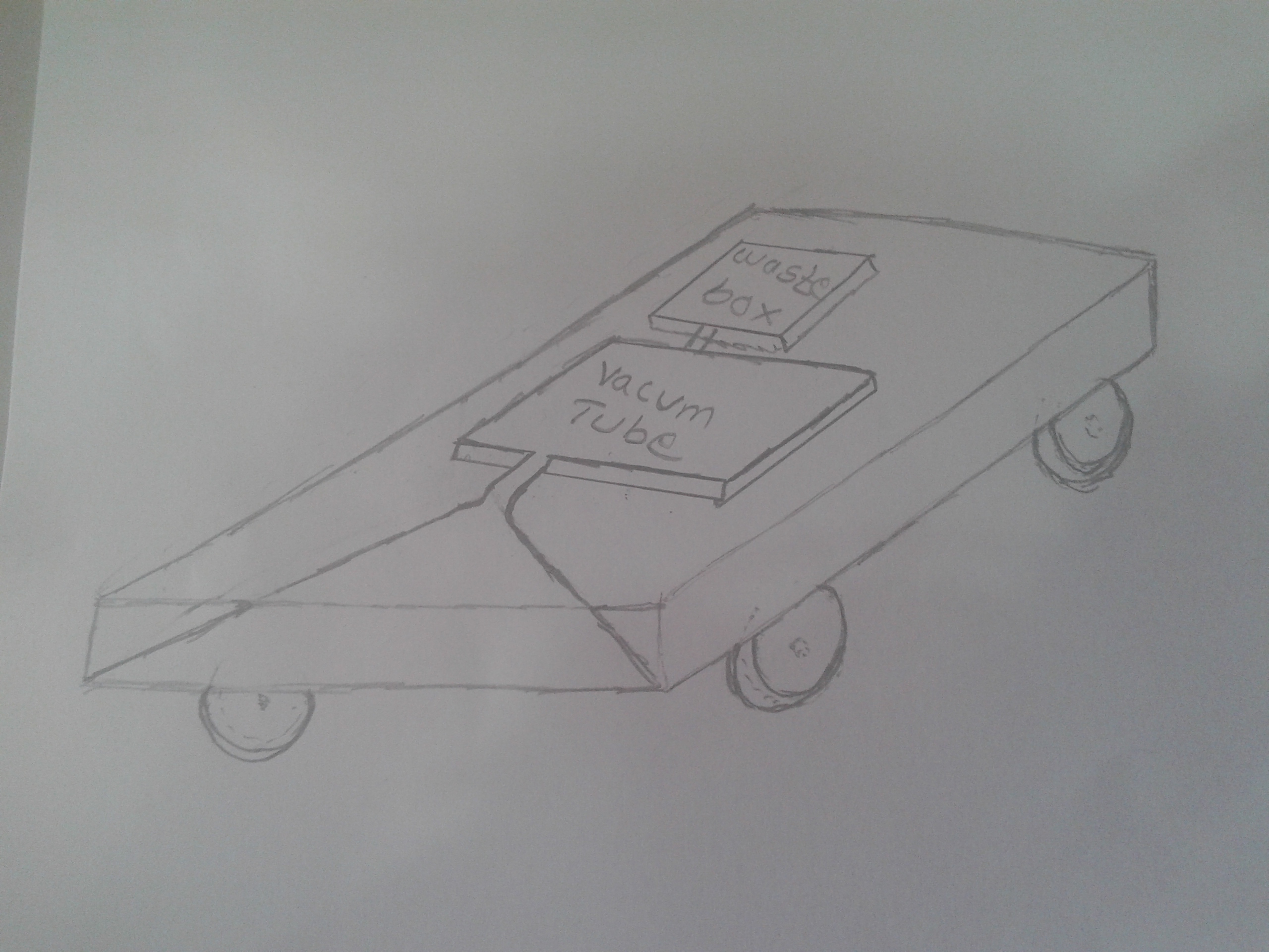
Rough sketch
Firstly, I drew a rough sketch diagram of cleaning bot, and I created a basic structural idea of cleaning bot.
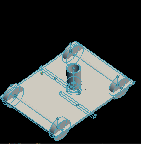
2D Desgining
The main advantage of the cleaning bot is it can avoid the obstacle on its path and clean remaining area.

3D Desgin
working concept
The working concept of the cleaning bot is, in above I described one advantage of cleaning bot it avoids the obstacle on its path, for this property have I am using an ultrasonic sensor for the detection of obstacles moreover first I am decided vacuum cleaner for the cleaning purpose but I change this process because vacuum cleaner is used to we can not clean perfectly and also very risk to clean sluggish particles instead of that I am used a rotating shaft attached to a cleaning cloth also I connected a water pump with the cloth for the cleaning purpose,and gear motor is using for the wheel movement.
Components
Then I take a list of components are required for this project.
-
Attiny44 microcontroller
-
ultrasonic sensor
-
motor driver
-
gear motor(five)
-
9v battery (two)
some details about components
ATtiny44 microcontroller
I have already documented the detail of ATtiny44 microcontroller in computer-aided design week
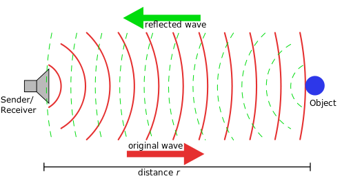
ultrasonic sensor
The ultrasonic sensor is measuring the properties of sound waves To elaborate it generate high frequency sound waves and evaluate the echo which is received back by the sensor, the Frequency of the sound wave above the human audible range.

How does an ultrasonic sensor working
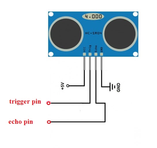
pin diagram of ultrasonic sensor module
motor driver
A motor driver is a little current amplifier; the motor driver function is to take a low current control signal and then turn it into a higher current signal that can drive a motor.The motor driver is using in different applications
-
Relay and solenoid switching
-
Stepping motor
-
LED and incandescent displays
-
Automotive applications
-
Audio visual equipment
-
PC Peripherals
-
Car audios
-
Car navigation systems
The motor driver is mainly using the controlling of the motor.A motor driver is used to we can control two motors at a time H bridge bridge principle is using for the controlling process
circuit diagram o H bridge principle

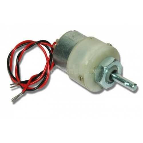
Gear motor
A geared DC Motor has a gear assembly attached to the motor. The speed of the motor is counted regarding rotations of the shaft per minute and is termed as RPM.The gear assembly helps in increasing the torque and reducing the speed. Using the correct combination of gears in a gear motor, its speed can be reduced to any desirable figure. This concept where gears reduce the speed of the vehicle but increase its torque is known as gear reduction.
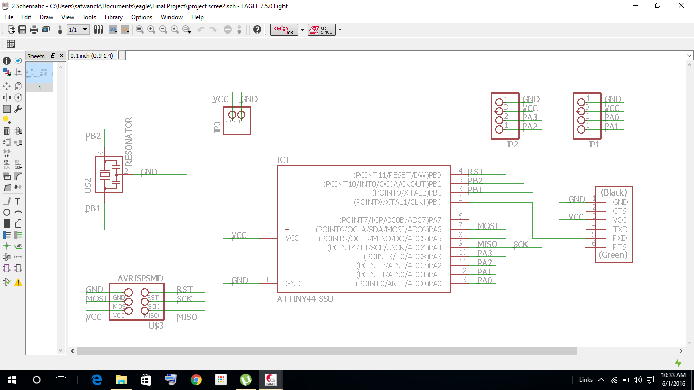
Electronic design and Production
then I started the designing by Eagle software is used, before the design I think once again what are all the input and output connections are wanted from the microcontroller, the schematic diagram is shown below
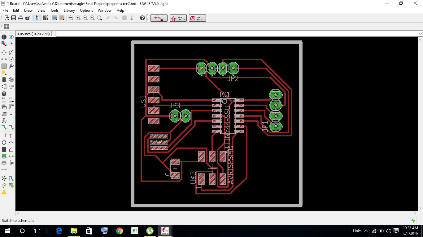
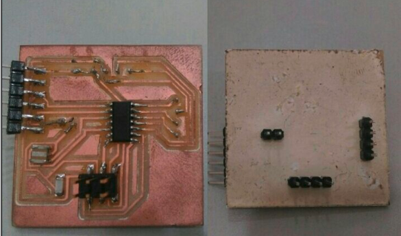
trace and cut part are ready for milling
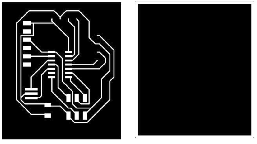
milled the board and I stuff the board
designing
Rhino 3D Software is used to complete the chase design work.
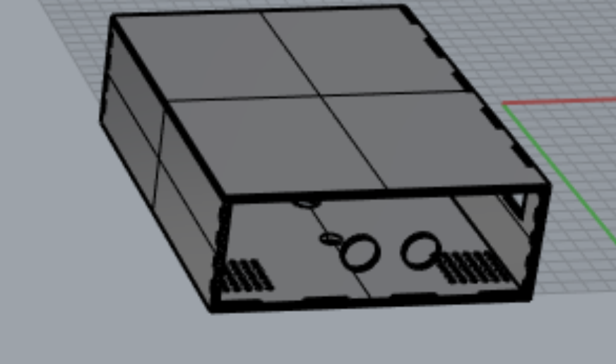
in this 3D we can see the ultrasonic sensor fixing plate and tyre connecting places
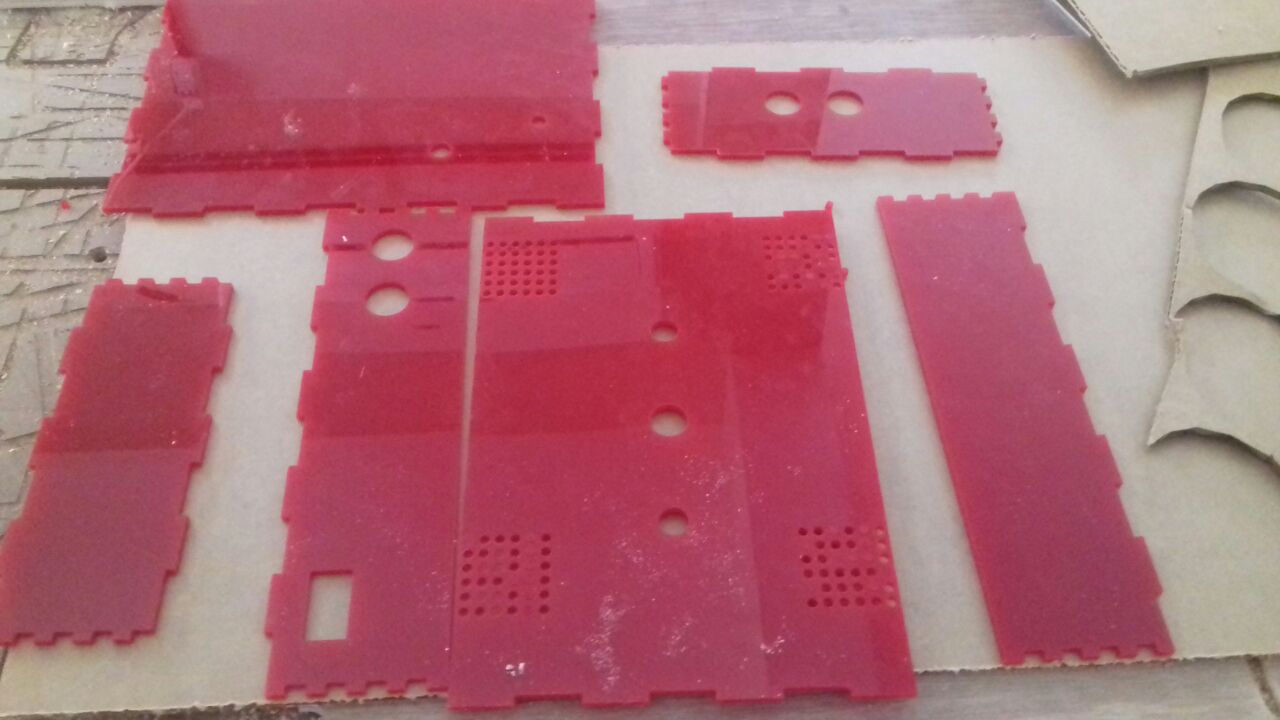
laser cutting
Acrylic is using for the chase creation for that laser cutter is used for the Acrylic cutting.
Ultrsonic sensor test
The ultrasonic sensor is the input part of the cleaning bot.In this project I have using an ultrasonic sensor for the detection of obstacle.i am connected an external LED with my board, and I programmed in Arduino if any obstacle will come to the programming area then the LED will be blink.
arduino program
    #include <Ultrasonic.h>

    Ultrasonic ultrasonic(0,1); // (Trig PIN,Echo PIN)
    int Range;
    int dist;

    int LED1 = 3;  // LED1 Pin

    void setup()
    {
      pinMode(LED1, OUTPUT);
      dist = 30;


    }
    void loop()
    {


    Range = ultrasonic.Ranging(CM);
    if (Range < dist)
    {
      digitalWrite(LED1,HIGH);
    }
    else if (Range > dist)
     {
    digitalWrite(LED1, LOW);
    }

    }
result
output part
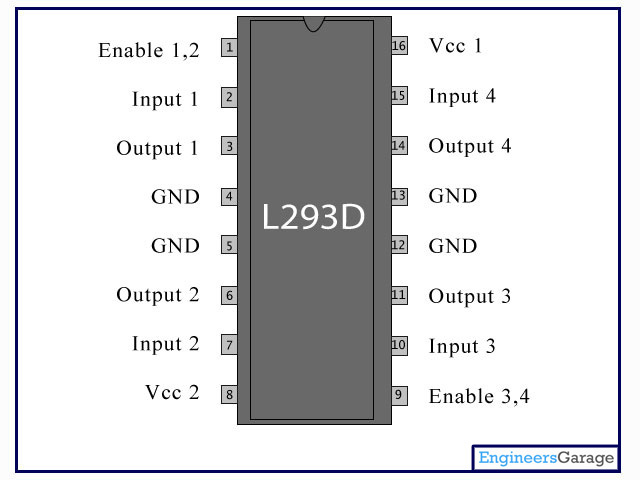
The gear motor is the output part of cleaning bot in here I have connected the gear motor with L293D motor driver IC, which allows DC motor to drive in either direction.L293D is a 16-pin IC, which can control a set of two DC motors simultaneously in any direction.
how to drive
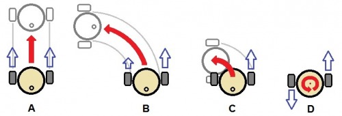
When both tyres move simultaneously forward the direction of the bot forward direction if left side stops the rotation, and the right side is moving forward the direction of the bot is left side else, the right side is stopped, and left side is move in forwarding the direction of the bot is right side or one side is moving forward and one side in move opposite direction the bot will rotate.Like, wise the movement will be occurring.
Assempling the input and output unit with microcontroller
Firstly I connected the ultrasonic sensor into the microcontroller already I discussed the connection of ultrasonic sensor, one is connected to the ground and a VCC also two input pins, input session is completed.Then I move to the output session four data pins are connected from the microcontroller to motor driver. And to get one VCC and a GND to motor driver.In here I am using 9v battery that is why I use a voltage regulator between the microcontroller and battery.We don’t give above 5.5V directly to the ATtiny microcontroller.The cleaning process I connected a motor with switch.


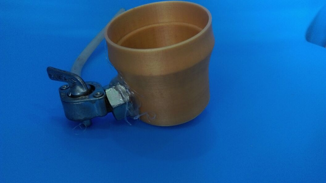
water storage
Water is using for the cleaning process that is why I have connected a water regulator with water storage.Ant fit with the cleaning bot.when we cleaning time the water regulator is used to adjust the water
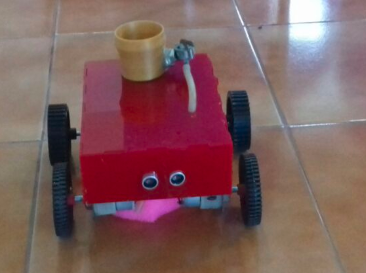
final image
programming
/*
* Cleaning Bot
*
*/


  #include <Ultrasonic.h>
  Ultrasonic ultrasonic(6,7); // (Trig PIN,Echo PIN)
  int Range;
  int dist;

  int LeftMotorForward = 0; // Pin 10 has Left Motor connected on Arduino boards.
  int LeftMotorReverse = 1; // Pin 9 has Left Motor connected on Arduino boards.

  int RightMotorForward = 2; // Pin 12 has Right Motor connected on Arduino boards.
  int RightMotorReverse = 3; // Pin 13 has Right Motor connected on Arduino boards.

  int trigger_pin =6;
  int echo_pin =7;

  int dist =30;

  void setup()
  {
    pinMode(LeftMotorForward, OUTPUT);  // initialize the  pin as an output.
    pinMode(RightMotorForward, OUTPUT);  // initialize the  pin as an output.
    pinMode(LeftMotorReverse, OUTPUT);  // initialize the  pin as an output.
    pinMode(RightMotorReverse, OUTPUT);  // initialize the  pin as an output.
  }
  void loop()
  {
    Range = ultrasonic.Ranging(CM);
    if (Range > dist)
    {
      digitalWrite(RightMotorForward, HIGH);   // turn the Right Motor ON
      digitalWrite(LeftMotorForward, HIGH);   // turn the Left Motor ON

    }
    else
    {
      void Rightturn();

      digitalWrite(RightMotorForward, LOW);   // turn the Right Motor OFF
      digitalWrite(LeftMotorForward, HIGH);   // turn the Left Motor ON
      delay(10000);               // wait for  10 seconds

      digitalWrite(RightMotorForward,LOW);   // turn the Right Motor OFF
      digitalWrite(LeftMotorForward, LOW);   // turn the Left Motor OFF

      delay(10000);
      digitalWrite(RightMotorForward, HIGH);   // turn the Right Motor ON
      digitalWrite(LeftMotorForward, HIGH);   // turn the Left Motor ON
      break();

    }