Week 13 : Output Devices
Assignment
This week assignment is add an output device to a microcontroller and programming it.
I have decided to conect a RGB LED with microcontroller.this are all the steps for completing this assinments.
- Design the circuit
- milled pcb
- solder it
- microcontroller Programming
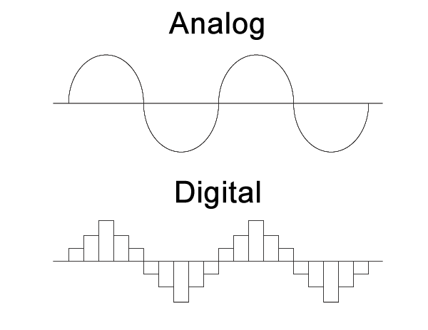
different between analog and digital output
analog
Analog technology, information is translated into electric pulses of varying amplitude, the signal is a continuous signal which represents physical measurements.The analog signal Waves Denoted by sine waves.Data transmissions time Subjected to deterioration by noise during transmission and write/read cycle.The example of analog is Human voice in the air, analog electronic devices.
digital
Digital technology, translation of information is into binary format (zero or one) where each bit is representative of two distinct amplitudes. Digital signals are discrete time signals generated by digital modulation.The analog signal waves are Denoted by square waves.The main comparison of digital Can be noise-immune without deterioration during transmission and write/read cycle.The example of digital out is Computers, CDs, DVDs, and other digital electronic devices.
What is RGB LED
A single LED die can only emit monochromati light which could be one of three primary colurs -red,green and blue is called RGB LED.
Design the circuit
It is the first step .for the Designing purpouse i used eagle.for the component selection i allready installed fab modules in my electronic design week moreover i study littil bit using eagle,that is why my desgin side is completed Rapidly.
Eagle Screenshots: 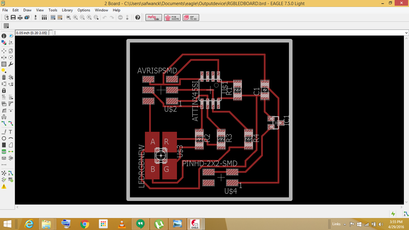
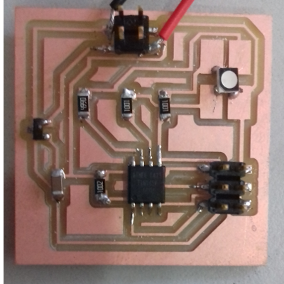
milled and stuffing the board
After completing my design i started to mill using Rolend modela unfortunatly in this week my first attempt is sucessfull becuse i set correctly in design rules, last time i got plenty of mistakes for that now i am baihart the design rules. after completing my milling i started to soldring.i dont know ,now itself soldring is a herculian task appart from me becuse that’s much of hand shevaring when i start to soldring at last i did it.
microcontroller Programming
I used arduino program for this
  int redPin = 1;
  int greenPin = 2;
  int bluePin = 0;


  void setup()
  {
    pinMode(redPin, OUTPUT);
    pinMode(greenPin, OUTPUT);
    pinMode(bluePin, OUTPUT);
  }

  void loop()
  {
    setColor(255, 0, 0);
    delay(1000);
    setColor(0, 255, 0);
    delay(1000);
    setColor(0, 0, 255);
    delay(1000);
    setColor(255, 255, 0);
    delay(1000);
    setColor(80, 0, 80);
    delay(1000);
    setColor(0, 255, 255);
    delay(1000);
  }

  void setColor(int red, int green, int blue)
  {

    red = 255 - red;
    green = 255 - green;
    blue = 255 - blue;
    #endif
    analogWrite(redPin, red);
    analogWrite(greenPin, green);
    analogWrite(bluePin, blue);
  }
conecting to system for Programming.
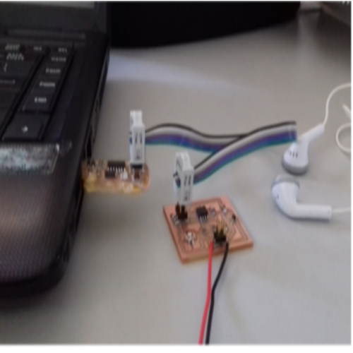
Output
fainaly i got out put of RGB LED,it is blinking of three diffrent colourly
download orginal files