Input Devices
Assignment
this week assignment is added an input device to a microcontroller and programming it
what is sensor
A Sensor is a device that detacte some type of information from the enviornment such as heat,motion,moisture,light etc. then the out put is genarly a signal then it convert humman readable display.
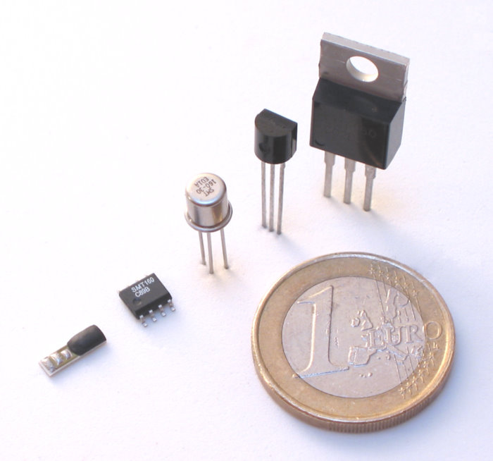
Temprature sensor
This device gives temperature measurement as an electrical signal is called as Temperature sensor. This electrical signal will be in the form of electrical voltage and is proportional to the temperature measurement. The different type of temperature sensors like, Thermistor, Thermocouple, Resistance thermometer and Silicon band gap temperature sensor, this are using in different applications
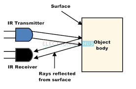
IR sensor
This device detects infrared radiation to sense a particular phase in the environment.Thermal radiation is emitted by all the objects in the infrared spectrum.The infrared radiation is not visible to human eye. The working principle of IR sensor is IR LEDs to send the infrared waves to the object. Another IR diode of the same type is to be used to detect the reflected wave from the object.
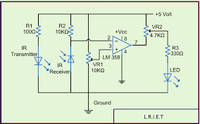
circuit diagram of iR
application of IR sensor
Thermography: it is possible to view the environment with or without visible illumination using thermography.
Communications: IR laser provides light for optical fiber communication. These radiations are also used for short-range communications among mobiles and computer peripherals.
Climatology: Monitoring the energy exchange between the atmosphere and earth.
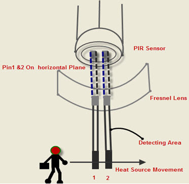
PIR sensor An electronic sensor used for measuring the infrared light radiation emitted from objects in its field of view is called as a PIR sensor.It is a motion detector; it is used to analyze the motion of object .they are commonly used in burglar alarms and automatically-activated lighting systems.
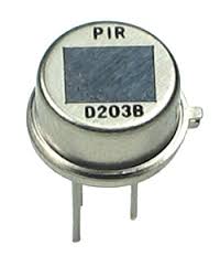
working process of a PIR sensor Every object that has a temperature above absolute zero emit heat energy in the form of radiation radiating at infrared wavelengths
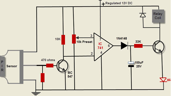
PIR circuit diagram
ultrasonic sensor
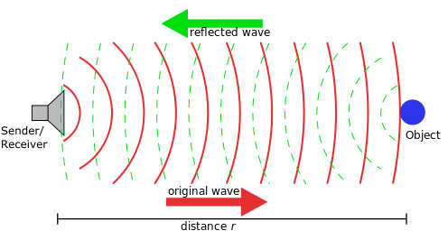
The ultrasonic sensor is measuring the properties of sound waves To elaborate it generate high-frequency sound waves and evaluate the echo which is received back by the sensor, the Frequency of the sound wave above the human audible range.

How does an ultrasonic sensor working
pin diagram of ultrasonic sensor module
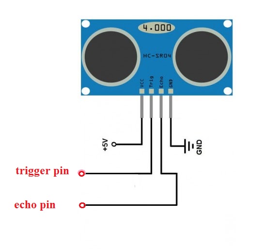
In my final project, i am using ultrasonic sensor for analyzing object for that I decided to attach an ultrasonic sensor module with the microcontroller.
Desgining board
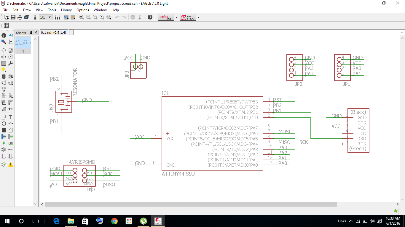
I started the design work in eagle software and i added some extra pins in this board because it usefull for in my final project
here is the schematic
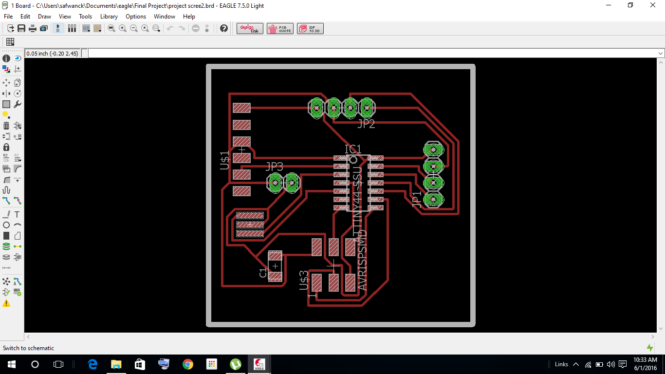
layout
here are the original files
Board Production
trace layout
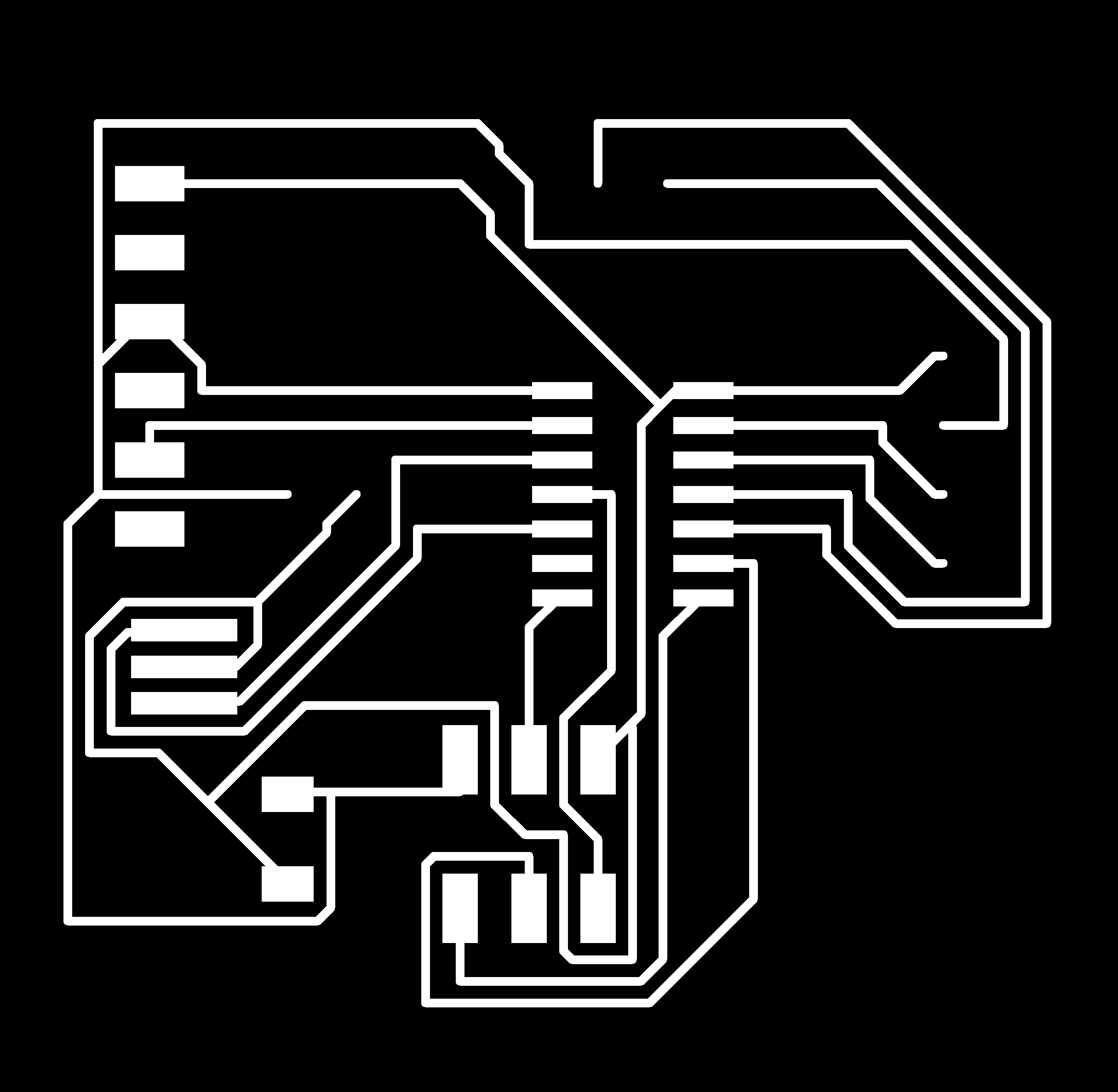
pad layout

cutout

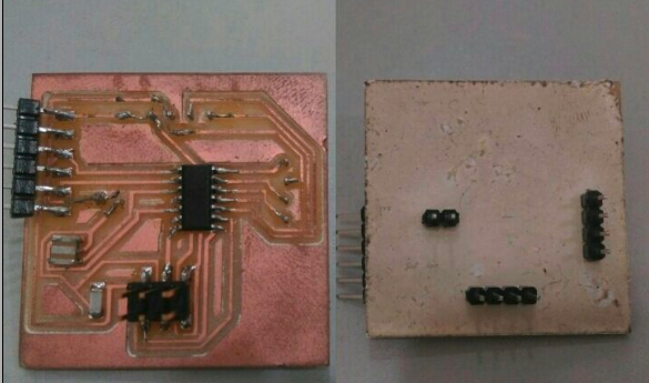
milling and stuffing the board
microcontroller programming
Arduino program is used for the microcontroller programming.And I decided the program is if any obstacle will come on the programming distance that time Led will blink. This board I have connected the ultrasonic sensor Trig pin to microcontroller pin”zero” and echo pin connected to pin “one” another two pins of ultrasonic sensor one are ground another one is VCC. Unfortunately, I am not designed the Led in my circuit that is why I am connected an external Led with 499ohm resistor to the microcontroller pin number”three.”
  #include <Ultrasonic.h>

  Ultrasonic ultrasonic(0,1); // (Trig PIN,Echo PIN)
  int Range;
  int dist;

  int LED1 = 3;  // LED1 Pin

  void setup() {
    pinMode(LED1, OUTPUT);
    dist = 30;


  }

  void loop()
  {


    Range = ultrasonic.Ranging(CM);
    if (Range < dist)
     {
       digitalWrite(LED1,HIGH);
       }
        else if (Range > dist) {
          digitalWrite(LED1, LOW);
        }

      }