I started my project with a strong will of making something in the wearable domain, so was in mess of choosing an idea to fit my aspects about my fab project.
So I started researching and finalized to make one ring that helps to do simple tasks like slide transition, volume rocker, play, and pause, etc..
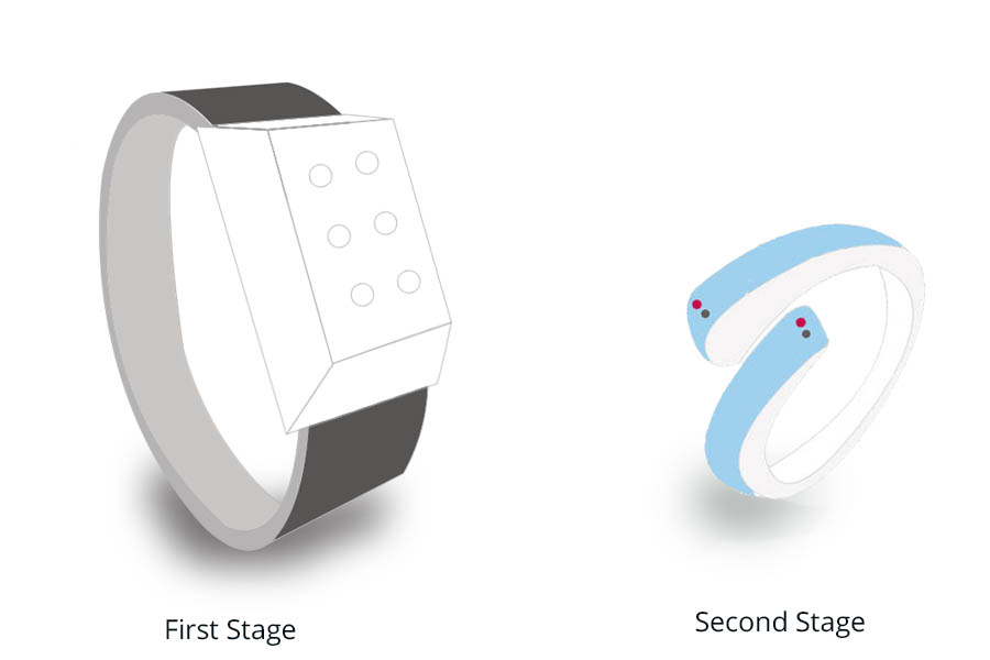
But right now with available component and time constraints to minimize the board size to that extent will be a limitation, so I decided to develop my project with two stages.
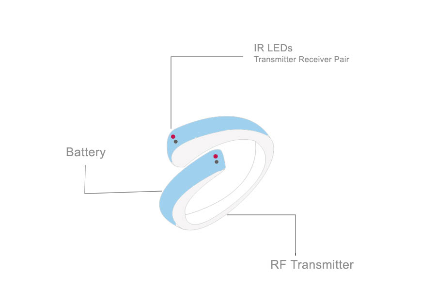
In the first stage, I am going to make a bracelet for controlling mobile and computer, then in the second stage reduces the size and embedded into ring
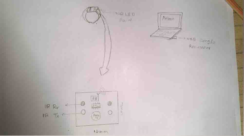
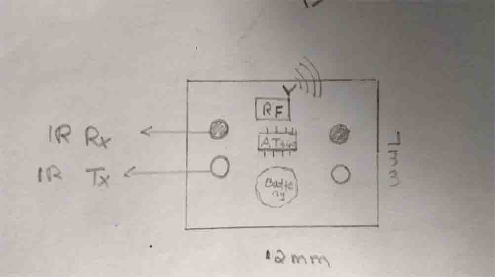
The first stage of my project is making a rough idea about structure, size and working of the project for this I start to draw a rough hand sketch of the project. I draw this sketch is based on Working of the project
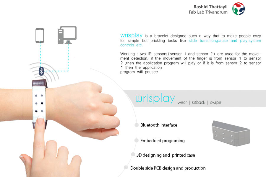
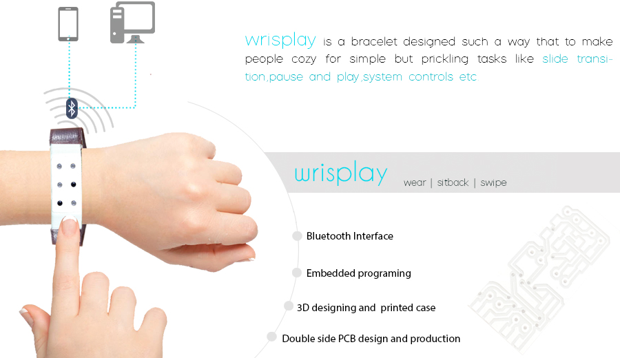
Working : two IR sensors(sensor 1 and sensor 2) are used for
the movement detection. if the movement of the finger is from
sensor 1 to sensor 2 ,then the value "1"or if it is from sensor 2 to sensor 1 then then sent value "0"
This rough sketch is helped me to start design 2Dstructure of the project
Then I start to design the 2d structure of my project. Here I am creating the structure for two stages of the project.
I start to design 2d structure of bracelet for the first stage. I feel more comfortable with Photoshop than Gimp, so I decided to use Adobe Photoshop for design 2d structure of bracelet
Show more details and files about designing in my computer aided designing week
Download all 2D design files of ring (gimp files)
Download 2D design files of bracelet (Photosh files)
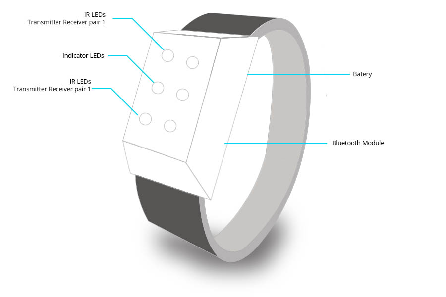
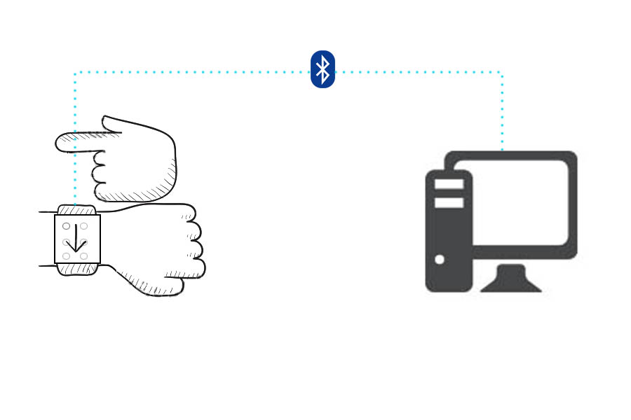
In this project, I am using two IR transmitter receiver (transceiver ) pair sensors for detecting direction of movement of the finger.
If the flow of the finger is from
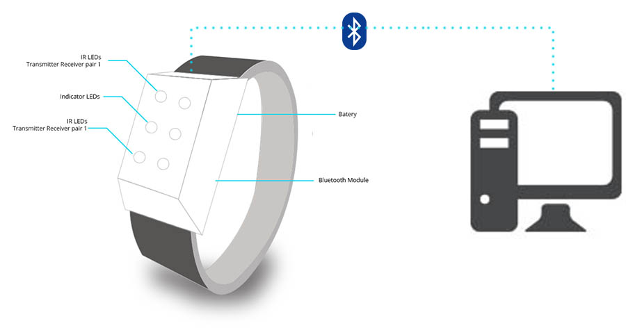
sensor 1 to sensor 2, then the value "1" or if it is from sensor 2 to sensor 1 then sent value "0.".This is interfaced to the system via Bluetooth and can control the system within the 10-meter range
Here circuit works on the principle of IR sensing. Two sets of IR transmitter-receiver pair are placed at two ends of the case holder. The output from each sensor is fed to the microcontroller. In normal operation, IR light from the IR transmitter LED would not fall on the IR receiver, this time, The output from the sensor would be a logic low signal in this case. In the case of any interruption (due to finger crossing just above the IR LEDs) the IR light is reflected back, this time, IR receiver receive some amount of IR light, the receiver would cease to conduct or conduct less, and the output from the sensor would be a logic high signal. The transition from low to high, for each sensor pair, is detected by the microcontroller and accordingly the move would be left or right (down or up).
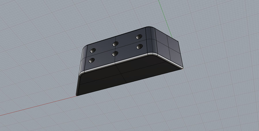
I started to make the 3D model of the case holder based on my 2D design of the bracelet. 3D case holder design is one of biggest challenge for me, the design must be small and can be embedded my whole circuit into the case . and its shape must be useful and easy to use
I did 3d design of case holder using Rhino 3D software .
Show more details and files about designing in my computer aided designing week
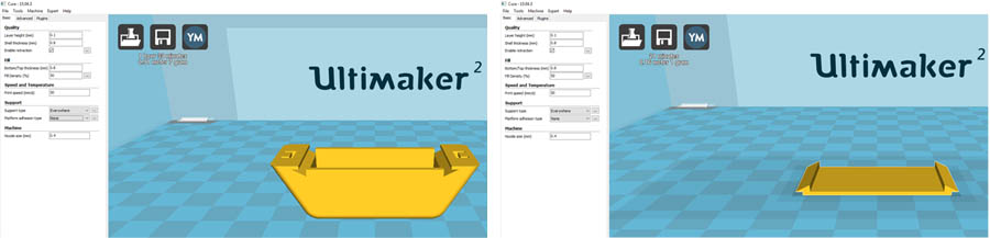
I use 3d printer ultimaker 2 for print my case holder . and make the quality setup is shown below to get a good quality print with a minimum time . I use cura 3D printing software to generate gcode file , Cura creates a seamless integration between hardware, software, and materials for the best 3D printing experience
In this project, I need a Non-contact position sensor for this I start to study about different sensors
Phototransistor
first I desired use phototransistor.I start to study about working of the phototransistor. I understand one thing photo transistor is similar to an ordinary bipolar junction transistor except that no base terminal is provided. Instead of base current, the input to the transistor is provided in the form of light.
After studying about photo tram]nsistor I understand one thing it is tough to use phototransistor for detecting the direction of motion in my final project. The main reason is the output value of the phototransistor varying on surrounding light. Show more details on my input week page.
IR receiverr
I start to study about working of the IR transceivers. I fount that IR transceivers can overcome the limitations of the phototransistor.
An infrared receiver or IR receiver outputs a code to identify uniquely the infrared signal that it receives.
The IR transmitter LED transmits continuous IR rays, when reflective surface comes near to IR transmitter LED IR rays reflected back. Due to this reflection, the amount of IR rays received by an IR receiver LED is increased. An IR receiver LED output terminal value varies depending upon its amount of receiving of IR rays. Show more details on my input week page. Finally, I decided to use IR transmitter receiver pair as a sensor in my project
Before starting the circuit board design I study about several types of IR modules and IR circuits. Finally I decided to make a modified version of circuit shown in below. Main modification i made on this circuit is replacing LM358 with ATtiny 44 microcontroller and adding two pairs of IR transceivers
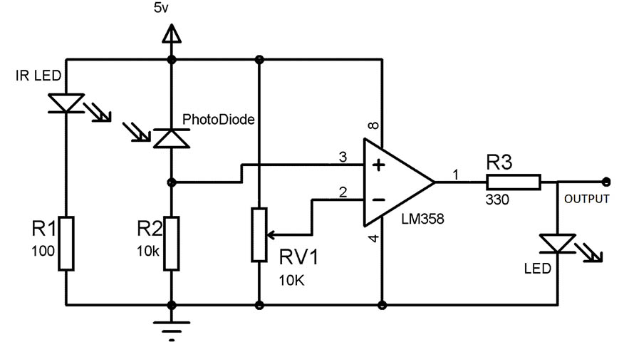
Then I star to design the board. In this board I using two IR transceivers used for the movement detection and Attiny 44 micro-controller for processing data from the IR receiver . And two blue color LED one is using for power indication in whole board and another one is for correct movement indication. Draw schematic circuit in eagle show in below
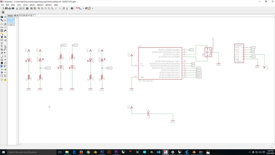
Download Schematic file (.sch)
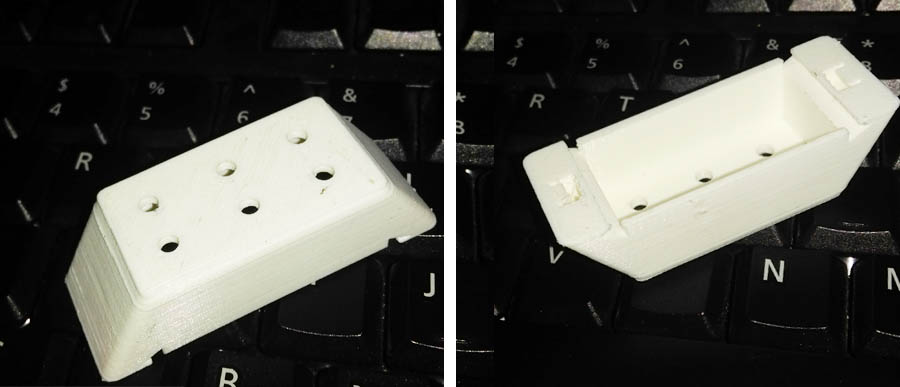
The designing of the board is tough because I wand to include this board into fixed size rectangular case shown in below (36mmx17mm), and position of LEDs must in the position of holes in the above 3d printed case
First, I locked LEDs and IR receivers in a fix the position on the board. Then start to arrange the position of other components. I compelled to make a double side design for getting the board in a size what I need
For reducing maximum size In this board both FTDI cable and ISP programmer connecting to FTDI header . for this I set MISO and MOSI to Tx and Rx pin of FTDI header
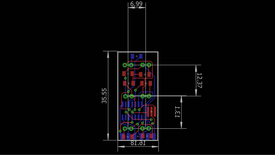
Download Board file (.brd)
show below the final result. Show more details about Board Design and Production on my input week page page.
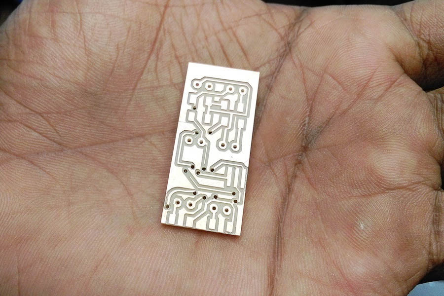
Download all files to Mill
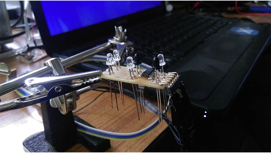
After milling the board I start to stuffing the board . Before soldering the components on the board I interconnect the via in the board, I use narrow copper wires to interconnect vias .After finishing connection of vias I start soldering the components into the board quite fast
show below the final result
Obtaining readings from the sensors :-
Here I am using two IR transceivers used for the movement detection.For Obtaining maximum and minimum readings from the sensors, connect the board to my computer using FTDI cable. Then continuously read IR receiver value using "analogRead" command in Arduino and use the serial monitor to show the range of values. I use the following program to read the values
Using above program, I got the maximum value from the sensor "900" ( when the finger very close to the sensor ) and minimum value "0" ( finger away from the sensor )
Then make a program for the finger movement detection. Here I using two IR sensors modules (sensor 1 and sensor 2),
If the finger is first above the sensor 1 input value to microcontroller I/O port of sensor one is 900, and sensor two is 0, this time, sent a string value " Move Left " via FTDI cable
Vice versa sensor two is 900, and sensor one is 0, this time, another sent a string value " Move Right "
First I Studied about different network protocols like WIFI/WIMAX Protocols,Bluetooth protocol,TCP/IP model etc. finally i decided to use Bluetooth protocol v2.0. I choose HC-05 Bluetooth Module for this, it is a commonly used bluetooth module .
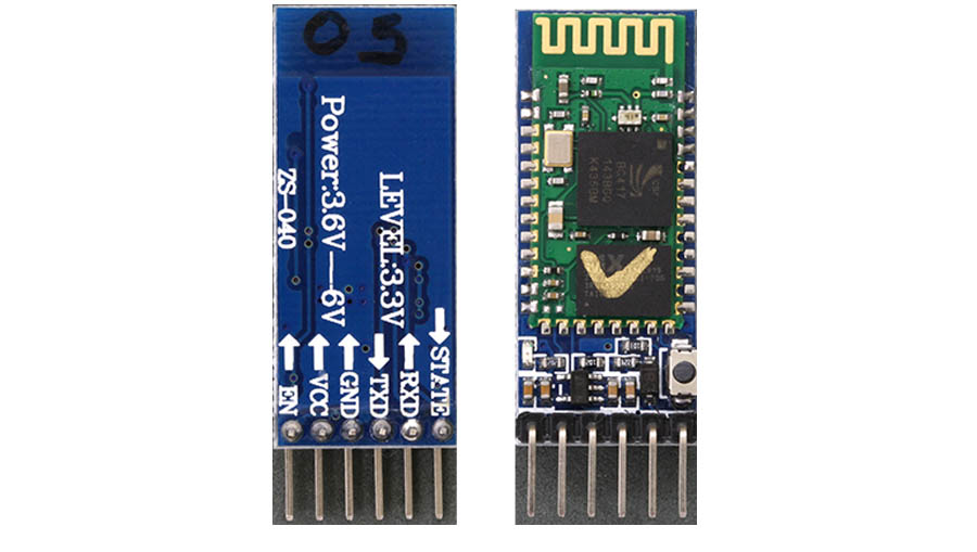
Specifications :-
Over the last few months, I have learned how to program with Python. In this projects that I am working on python for collecting data through Bluetooth and view the collected data on computer's display
For collecting data through Bluetooth I Creating a bluetooth serial port
After some searching I found pySerial. pySerial is an elegant piece of software that allows Python to send and receive data much like the Serial Monitor does
pySerial is available to download at https://pypi.python.org/pypi/pyserial
After download I install pySerial
To make sure that everything installed correctly open up Idle and type in 'Import Serial'. If no errors appears then everything is good to go
You can check the available ports with the line
Next, in Idle I create a new window and write a program to read data from Bluetooth
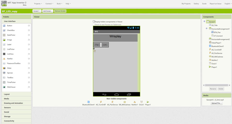
Build application with app inventor :- App Inventor is a visual, blocks language for building Android Apps. It is an open-source web application originally provided by Google, and now maintained by the Massachusetts Institute of Technology
I desired to build an android application for this project using app inventor
you can see my app in MIT App Inventor Gallery ai2.appinventor.mit.edu/?galleryId=5127150418264064
Application user interface on mobile :
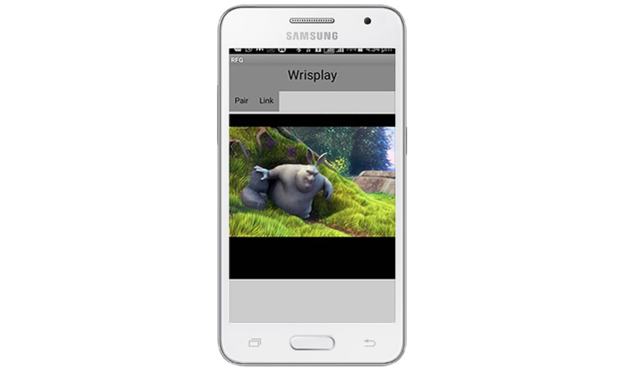
In this app I have add a small video, this video can play and pause using my bracelet (wrisplay ). In my bracelet have two IR sensors(sensor 1 and sensor 2) are using for The movement detection. If the movement of the finger is from sensor 1 to sensor 2, then the application program will play or if it is from sensor 2 to sensor 1 then the application the program will pause
For make this application I write the program when the value receiving trough Bluetooth is "0" then start the video player or receiving trough Bluetooth is "1" then stop the video player .show below my code
Code:
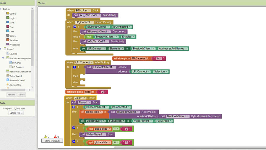
Application user interface:
I pulished my app in MIT App Inventor Gallery ai2.appinventor.mit.edu/?galleryId=5127150418264064 you will get both source code and apk file from that link
View the application
Download .apk File
show the working of app
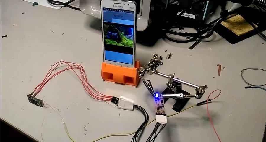
working video of app
After interface Bluetooth with my computer Creating a Bluetooth serial port and read data from the Bluetooth serial port ( shown above )
Then I write a python code for sending keyboard events corresponding to value receiving from Bluetooth serial port
If the finger wave off from "sensor 1" to "sensor 2 ", then receiving a value "1" via Bluetooth. That is the value of "a" is one . in this program when the value of "a" is "1" this time happening the same action on the computer when space button press. This cause to pause (if play) the video or cause to play (if pause) the video
slide