Assignement
measure something: add a sensor to a microcontroller board that you have designed and read it
What I am going to do
1)I want to make an accelerometer board that will communicate with a GUI 2)I want to read and caliberate data from a temperature sensor i have.
Input Devices
- The input is what sets an electrical circuit in action
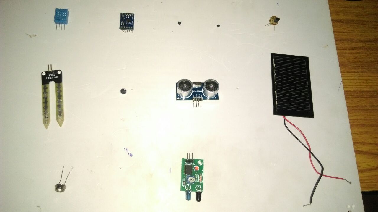
The input is what sets an electrical circuit in action,Any of the following components can be used as inputs
Switch
LDR
Thermister
Photodiode
Accelerometer
Temperature Sensor
Ultrasinic Sensor
IR Sensor
Keypad
Joystick
etc…
- Switch/Push Buttun
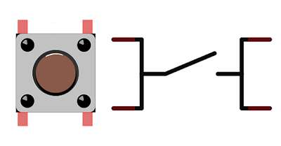
It is a simple switch mechanism for controlling some aspect of a devices or process , it makes circuit open and close .
Bouncing of Switch
When a switch is toggled, contacts have to physically move from one position to another. As the components of the switch settle into their new position, they mechanically
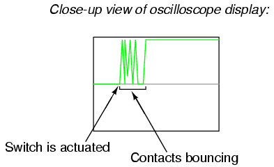
Image Source http://www.allaboutcircuits.com:
We can prevent this bouncing in diffrent ways , below circuit gives cro display of debounce switch it lokke perfect
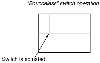
Image Source http://www.allaboutcircuits.com:
Debouncing Methods
We can debounce either electrinocally or programatically if we add an low pass filter in output of switch it will act as a debouncer and it prevent bouncing
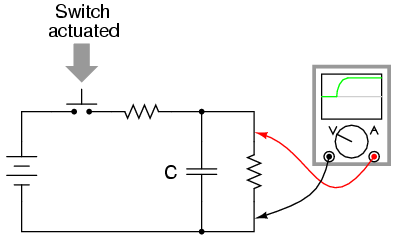
Image Source http://www.allaboutcircuits.com:
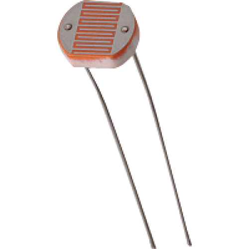
LDR
A photoresistor (or light-dependent resistor) is a light-controlled variable resistor. The resistance of a photoresistor decreases with increasing incident light intensity; in other words, it exhibits photoconductivity.
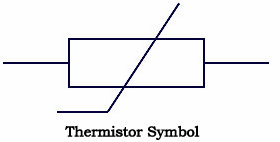
Thermister
It is electrical resistor whose resistance is greatly reduced by heating
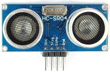
Ultrasonic Sensor
Ultrasonic transducers are transducers that convert ultrasound waves to electrical signals or vice versa ,Normally we are using HC-04 Ultrasonic Module
Accelerometer
Accelerometer is an Micro-Electro-Mechanical Systems device to meassure acceleration forces,it convert mechanical acceleretions to electrical signals.
I followed following youtube video and This PDF to understand about accelerometr working principle.
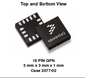
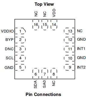
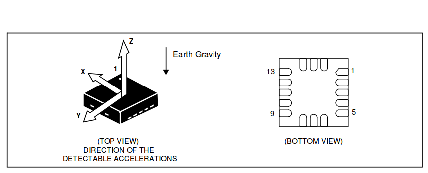
In our Fablab Inventory we have MMA845 Accelerometer
- first i want to study working of MMA845 Accelerometer ,Datasheet
-
-
-
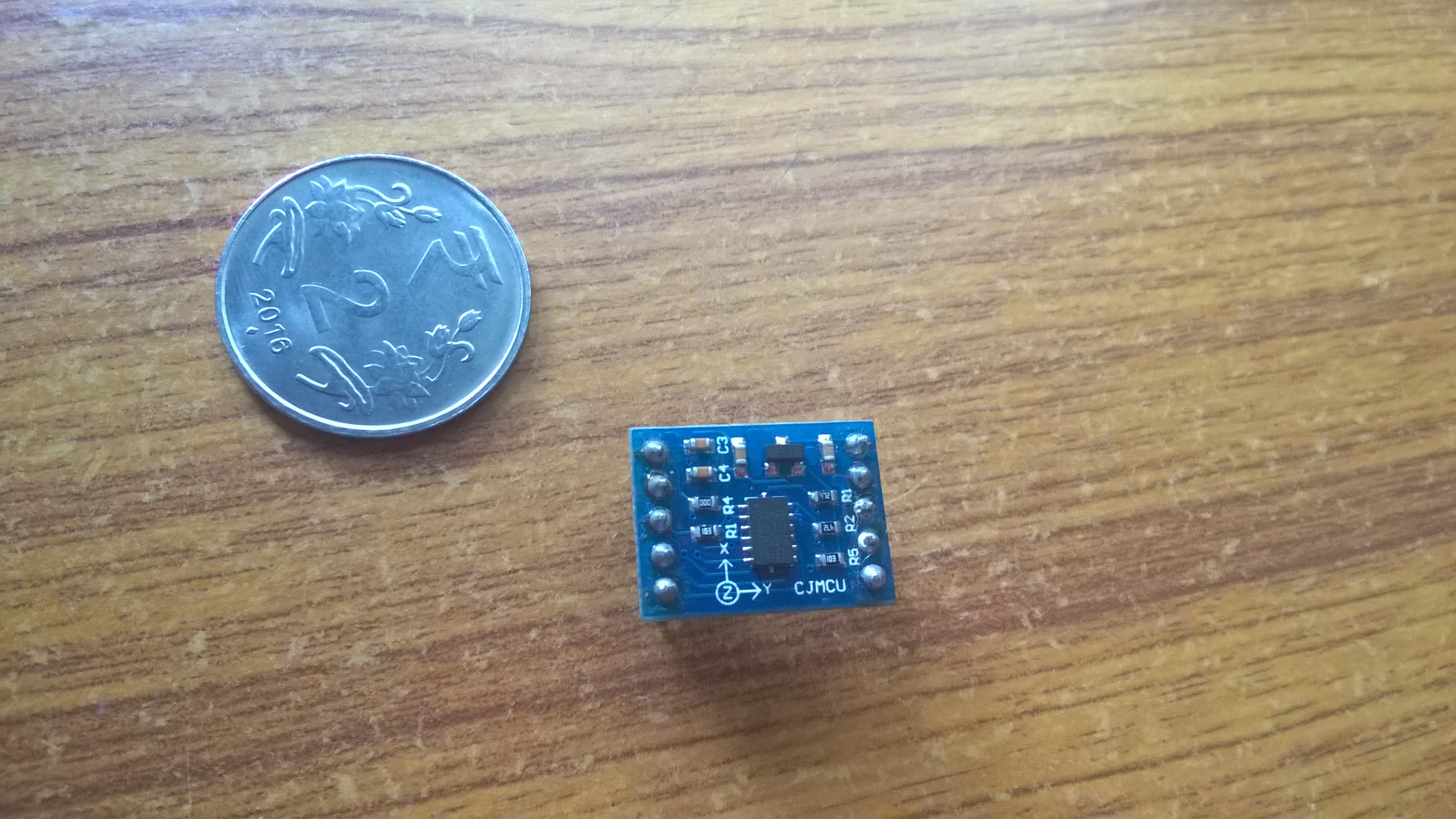
I tried to use this accelerometer in my board but the problem is MMA845 have very small foot print pad size(8 mil) , we need 1/128” bit for milling this size, but we have 1/64” and 1/32” bit only.
- I have an ADXL 345 Accelerometer , i am going to interface with attiny45 and communicate to GUI via serial .
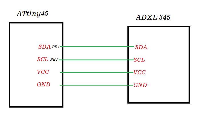
 We are using I2C Connection .
I2C Connection Between ADXL 345 and ATtiny45
- The Inter-integrated Circuit (I2C) Protocol is a protocol intended to allow multiple “slave” digital integrated circuits (“chips”) to communicate with one or more “master” chips , I2C connction requires only 2 wires (SDA and SCL) it is very useful in low pin Microcontrollers.
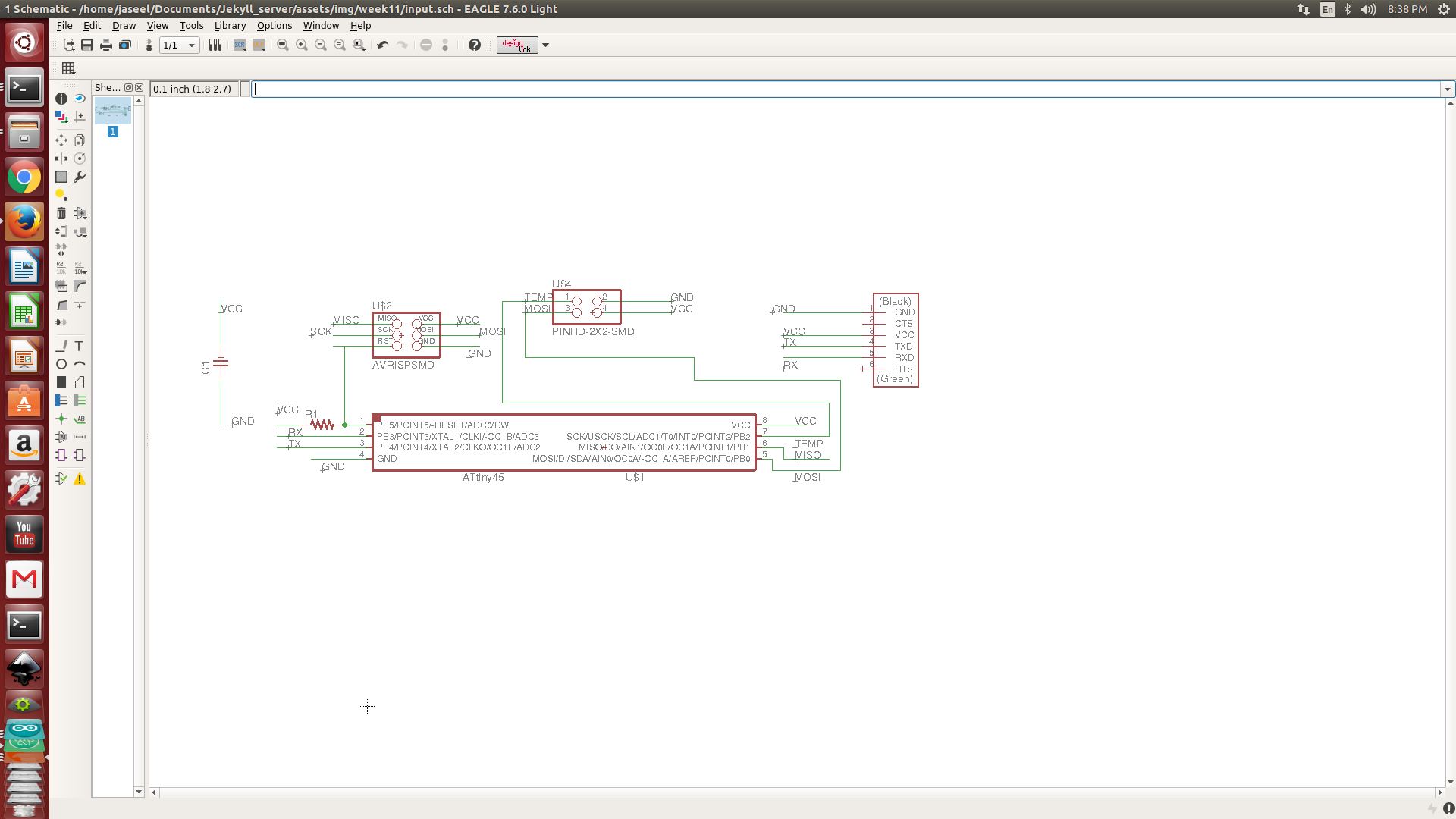
- I designed circuit in eagle,I used pinhead Component library for adding 6 Pin header for my accelerometer board, and i followed Neil’s ADXL343 Board for referance .
-
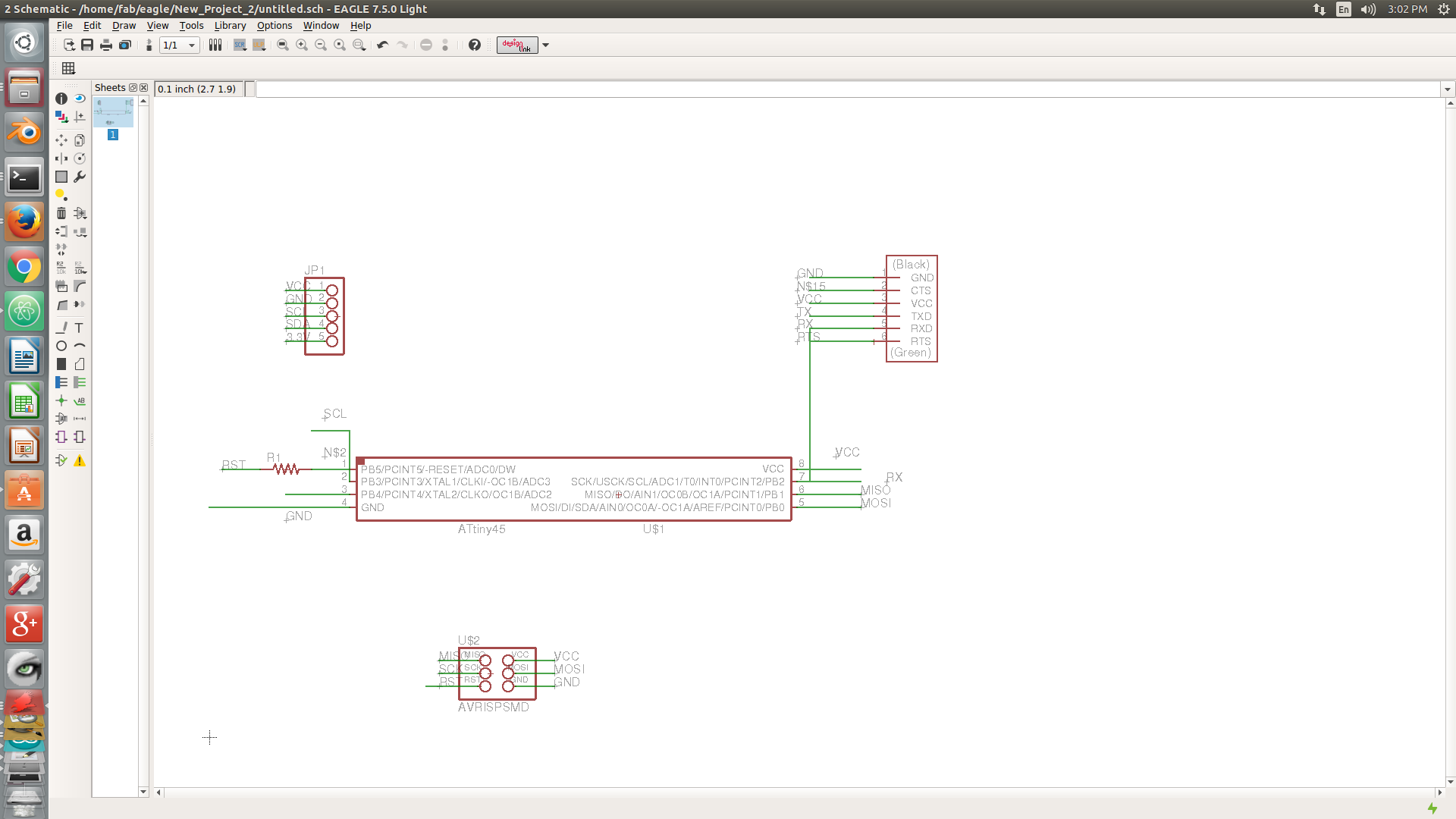
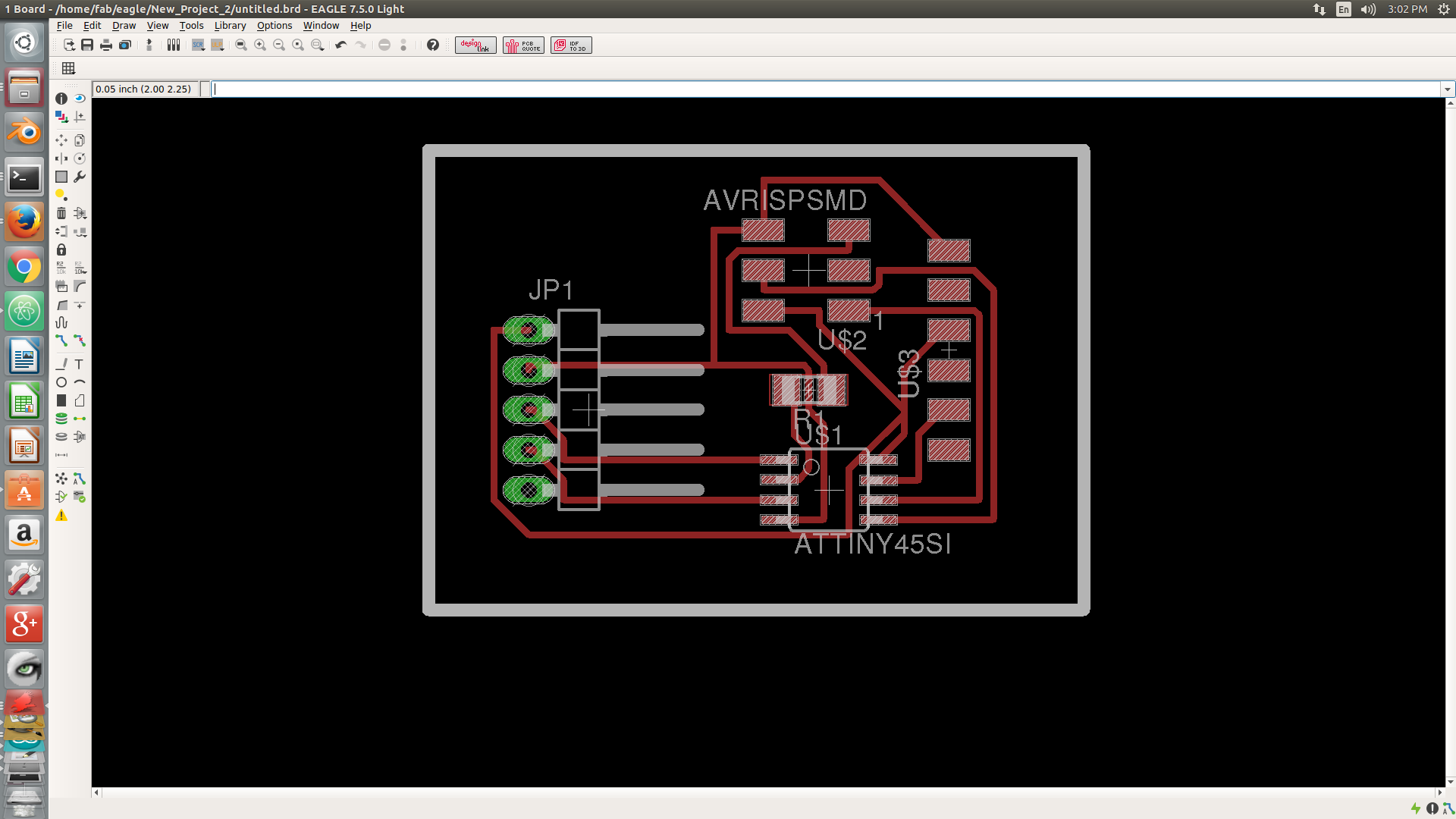
Download Eagle Files .Brd .Sch
- After Milling and Stuffing
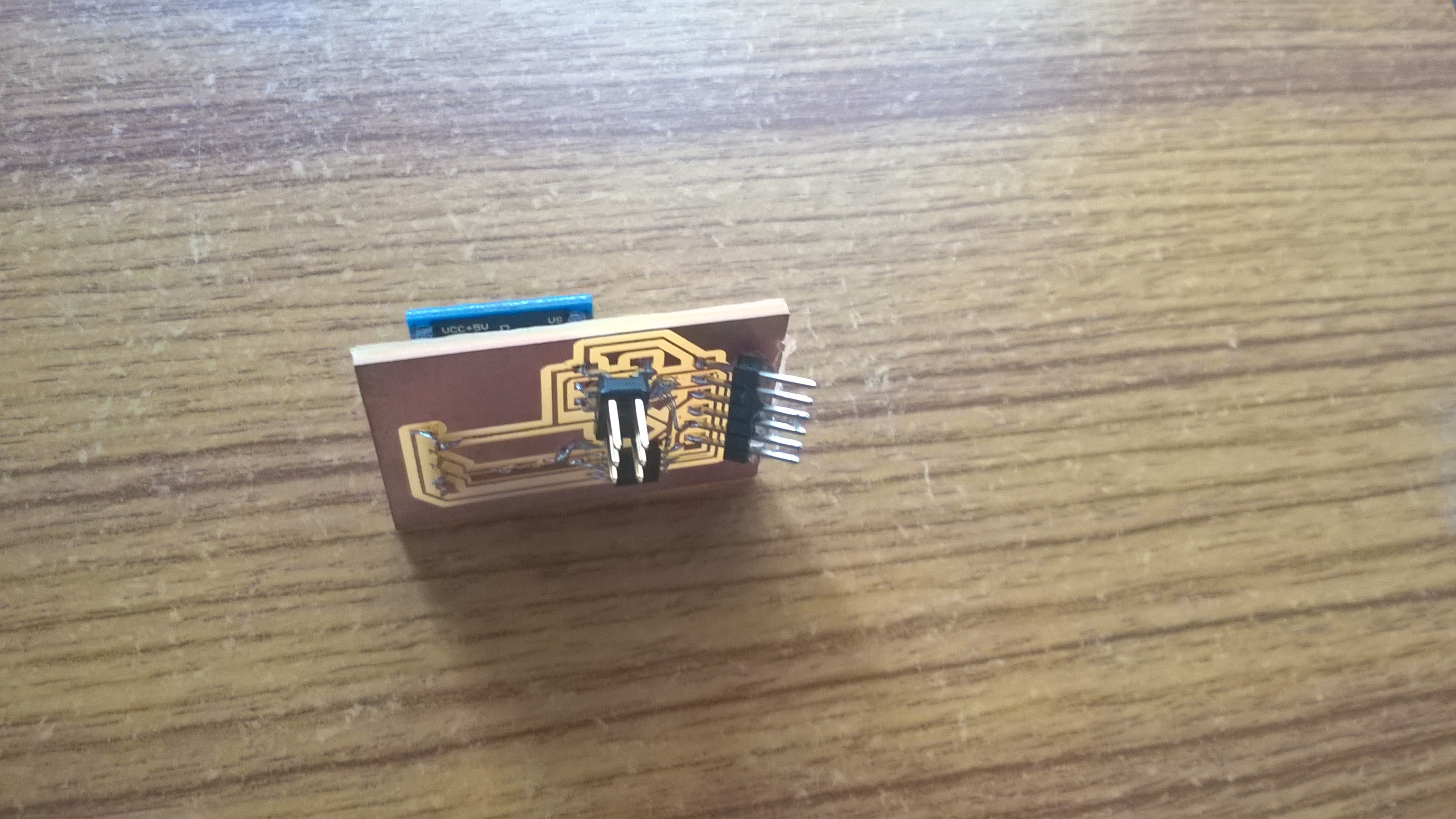 Back Side of Board
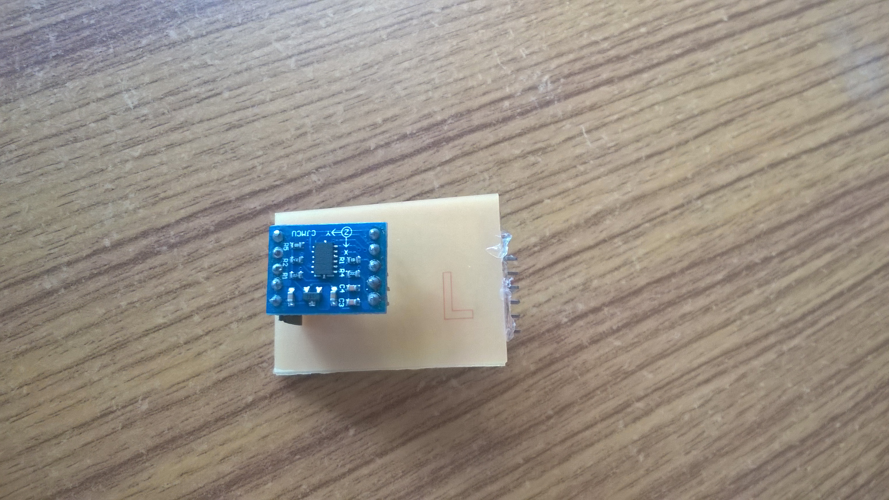 I connected this board to PC using FTDI Cable .
I used Neils ADXL 343 Code to Showing Accelerometer values in GUI. It working nice it visually indicating the accelrometer movements in X,Y and Z axis.
Final Result
Fab Academy_ Week 11 ADXL 345 and ATtiny45 from Jaseel on Vimeo.
Temperature Sensor
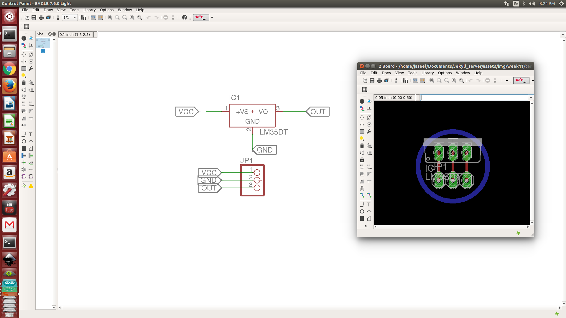
I already have an LM35 temperature sensor in my personal inventory i want to make a circuit for reading values from this sensor .
I created a Seperate circuit for ATtiny45 board and Temperature Sensor because i need to read temperature from outside, but i cant put my entire circuit outside thats why iam using seperate board for temperature sensor .
- Controller Board
-
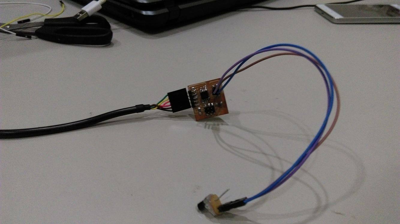
Caliberation of Temperature Sensor
I used Two Point Caliberation Method using an Ice-Water bath and Boiling Water for the two referances this is a linear temperature sensor thats why it will give good result in this method.
We know water boils at 100 Degree Celcious and Triple Point is 0.01 Degree Celcious
Referance Low = 0.01 Degree Celcious
Referance High =100 Degree Celcious
My Readings
Raw Low = 848
Raw High = 868
Raw Range = 20
put this values in Two Point Caliberation Equation
- CorrectedValue = (((RawValue – RawLow) * ReferenceRange) / RawRange) + ReferenceLow
-
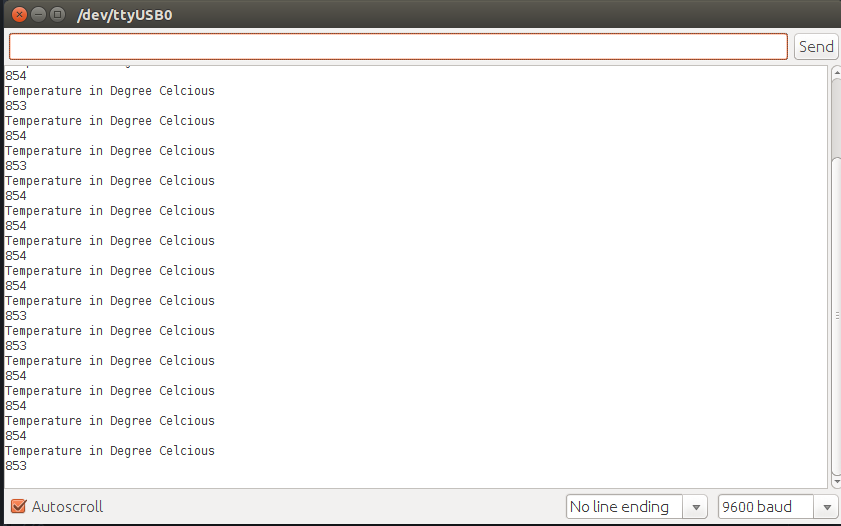 At room temperature i am getting Raw Value = 854 from temperature sensor ,
           CorrectedValue = (((RawValue – RawLow) * ReferenceRange) / RawRange) + ReferenceLow

          =(((854-848)*99.99/20)+0.01

          =30.007 Degree Celcious
Ya, it is almost correct i know meassuring devices should be accurate i need to make more accurate .
Temperature Sensor Caliberation from Jaseel on Vimeo.
Programming
/* Reading Data from LM35 Temperature Sensor
Muhammed Jaseel P
Fablab Trivandrum
*/
#include <SoftwareSerial.h>
   #define Rx 4
   #define Tx 3
   SoftwareSerial ftdi(Rx,Tx);
   void setup() {
   ftdi.begin(9600);
  }
   void loop()
  {
    if(ftdi.available() ){
    ftdi.println("Temperature in Degree Celcious");
    int RawValue  = analogRead(A1);//Raw Data from Sensor
    int CorrectedValue=((RawValue-848)*4.995)+0.01; // Caliberated Result
    ftdi.println(CorrectedValue);
    delay(2000);
    }
    }
Final Out
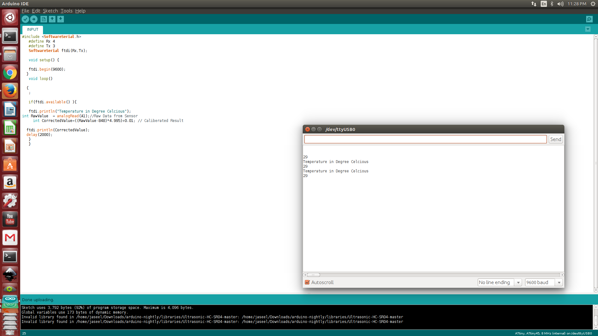
Problems Faced
when i am declaring CorrectedValue,RawValue as float arduino sketch become too big because it need more memmory to process float variables and i am using ATtiny 45 .
Sketch Too Big in Arduino IDE .
Sketch uses 4,516 bytes (110%) of program storage space. Maximum is 4,096 bytes. Global variables use 173 bytes of dynamic memory.
Solution
Write this Code in Embedded C ,it saves memmory space Change Microcontroller to higher memmory version ,in this case use ATtiny44