Embedded Programming
The assignment for this week is to read the datasheet of a board and program it do something. I am from electronics background and I am familiar with AVR, Arduino , Raspberry Pi etc. The board i made in the electronics design week is echo hello-world board with ATtiny 44. Actually I am not very much familiar with tiny44, I used to use ATmega8 and ATmega16 or ATmega32 for normal purpose(only those chips where available here in the local market). So I want to start from the datasheet.
Here is the datasheet of ATtiny44
There are many programming languages like C, aurduino, assembly etc, which can be chosen according to the convenience. According to me I prefer C. I guess majority will be using the Arduino since it is very simple. But if you are using arduino you wont be come to know whats happening inside (my view point).
So lets start with C. As the editor there are many editors available. But for me Atmel Studio (AVR studio) is the best. But there is no version fot MAC and Linux , it is only for Windows. For linux users we can use Eclips with AVR-gcc plug in.

Atmel studio is the IDE developed by Atmel for their chips. So everything related to AVR chips are included in the atmel studio. Their predicion during programming is very good. You can download it here.
For starting a project, the steps are :
This is the way we should follow. Once you compile, we will get the hex file in the project folder. (The location is given already)
Hello world!
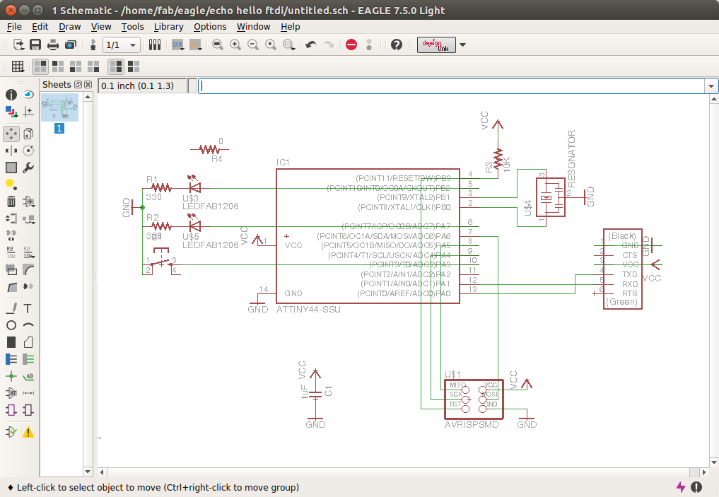
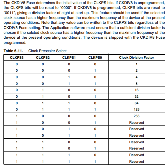
Lets start with an LED blinking hello world program. At present the echo hello world board i made has two leds ,a switch and a 20MHz resonator connected. Since the fuse bits are not set it is using the internal clock. It has a clock speed of 8MHz maximum but by default CKDIV8 will be enabled , so the clock will be 8MHz/8 = 1 MHz . CKDIV8 is a clock prescaler used to change the clock speed. Prescaler is used to scale the clock speed by some values. Take this case, the internal clock for ATTiny44 is 8MHz but if we want the clock as 1MHz then we can prescle it by 8 to get the desired clock.
Lets start coding, first see the ATTiny44 pin outs and the ports.
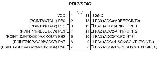
This chip has two ports , PORT A and PORT B. Port A has 8 pins and Port B has 4 pins. All these pins are general input output pins. In my connection leds are connected to PIN 5 and 6 (PB2 and PB7) and switch is connected to PIN 10 (PA3).
DDRB = 0xFFDDRB = 0b0001 // PB0 is output and PB3-1 is input
#define F_CPU 1000000           // Defining the clock speed as 1MHz
#include <avr/io.h>             // Importing the avr/io library (as stdio.h in the normal C)
#include <util/delay.h>         // Importing library for  delay (For blinking LEDs we need delay)


int main(void)
{


	DDRA = 0xFF;       //Set PORT A as output
	DDRB = 0xF;        //Set PORT B as output

    while(1)
    {


		PORTA|=(0b10000000);      //Make PA7 high
		PORTB|= (0b0100);         // Make PB2 high
		_delay_ms(1000);          // delay of 1 second
		PORTB=(0xFF);             // Make all pins in port B low
		PORTA=(0x0F);            // Make all pins in port A low
		_delay_ms(1000);         // delay of 1 second


	}
}
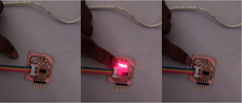
Next I will show how take an input -how to use the switch-. I have written a program to light the led when the switch is pressed.
 /* LED.c
 *
 * Created: 23-03-2016 23:58:32
 *  Author: YADU SHARON
 */


#include <avr/io.h>


int main(void)
{

	DDRA= 0b11110111;	// PA3 as input and all other pin as output
	DDRB= 0xF;			// PORTB as output
	PORTA|=(0b00001000);   // Pulling up the PA3 to which switch is connected

    while(1)
    {
		if (!(PINA & (1<<3)))
		{
			PORTA|=(1<<7);
			PORTB=0xf;
		}
		else
		{
			PORTA&=(0x0F);
			PORTB &=(0x0);
		}

    }
}
If you have some confusion with << operator (left shift) please refer here
Here is the C file and hex file
Using the external oscillator
If we want to use an external oscillator or resonator, just soldering it to the corresponding pins wont do anything but we have to tell the chip that we want to use it. We have already connected the resonator but still we were using the internal oscillator. In order to move to external we have to make some changes in the fuse bits. We have alreay programed the fuse bits and used the external oscillator during the fab isp week itself but very few people would be known of how the fuse byte are selected. Here I will explain it. For that we have to look in to the datasheet.
See the fuse byte registry (page no 160)
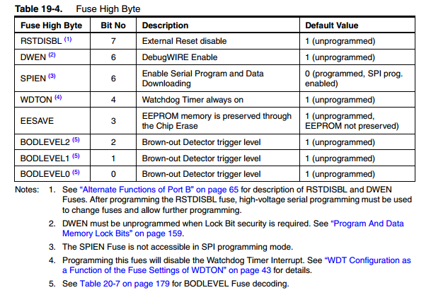
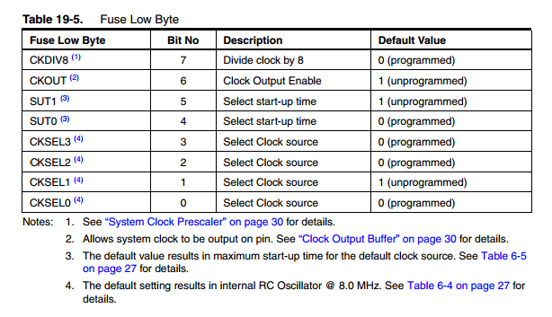
Lets look in to Fuse Low Byte.
CKDIV8 - This is a clock prescaler. If it is programmed the frequency will be prescaled by a division factor of 8. So if the clock frequency is 20MHz the resulting clock frequency would be 20/8 MHz. So if we want the clock frequency as 20MHz then this bit should be unprogramed. Look in to the table, 0 corresponds to "programmed". To unprogram it it should be 1. So we got the 7th bit of Fuse Low Byte.
CKOUT -The device can output the system clock on the CKOUT pin. To enable the output, the CKOUT fuse has to be programmed. This mode is suitable when the chip clock is used to drive other circuits on the system. At present we dont want it. So let it be 1.
CKSEL3:1 - This bits are selected according to the resonator/oscillator we are selecting.
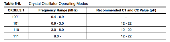
CKSEL, SUT1:0 - For selecting these bits please refer the table.
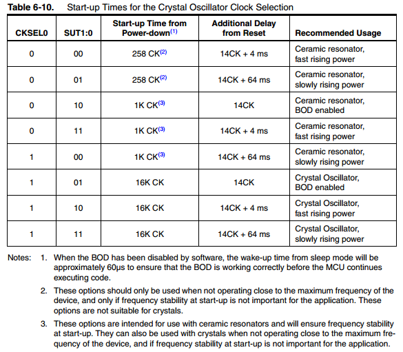
Since we are using the resonator , not the crystal the CKSEL0 is 0. For SUT values we should know about slow and fast rising power and about BOD. For that please refer this forum. That page is good for clearing your doubts.
Anyway I have selected the CKSEL0,SUT1,SUT0 bits as 001.
So we got all the bits of the Fuse Low Byte.
CKDIV8      1
CKOUT       1
SUT1        0
SUT0        1
CKSEL3      1
CKSEL2      1
CKSEL1      1
CKSEL0      0


Fuse Low Bye    :   1101 1110
                    D    E
AVRDUDE -c usbtiny -p attiny44 -U lfuse:w:DE:m
Now the clock is changed. So the F_CPU is to be defined as 20MHz. Lets try the same led blinking program again.
#define F_CPU 20000000           // Defining the clock speed as 20MHz
#include <avr/io.h>             // Importing the avr/io library (as stdio.h in the normal C)
#include <util/delay.h>         // Importing library for  delay (For blinking LEDs we need delay)


int main(void)
{


	DDRA = 0xFF;       //Set PORT A as output
	DDRB = 0xF;        //Set PORT B as output

    while(1)
    {


		PORTA|=(0b10000000);      //Make PA7 high
		PORTB|= (0b0100);         // Make PB2 high
		_delay_ms(1000);          // delay of 1 second
		PORTB=(0xFF);             // Make all pins in port B low
		PORTA=(0x0F);            // Make all pins in port A low
		_delay_ms(1000);         // delay of 1 second


	}
}
Assembly programming
the best arguement for why assembly is " while you live in France you are able to get through by speaking English, but you will never feel at home then, and life remains complicated". I got this from a nice and helpfull tutorial. For those who are familiar with C, the assembly is comparitevely simple. As the first step we need the following pdfsWithou the instruction set it id very difficult to ptogram.
Setting the environment:
I use gavrasm to compile and make the hex file from the .asm file. Download it and move to /usr/local/bin: so that you can use it from anywhere. Once you get the .hex file we can burn the chip with the avr dude. The steps are:
gavrasm file.asm
avrdude -c usbtiny -p attiny44 -U flash:w:file.hex
Hello world!
With the same board i used before, lets try some assembly codes. Here is the code for lighting an led which is connected to PORTA7
    .device attiny44
    .org 0

    sbi DDRA,7      ;make the PA7 as output
    main:
    sbi PORTA,7     ; make the PA7 high
    rjmp main       ; loop to the main
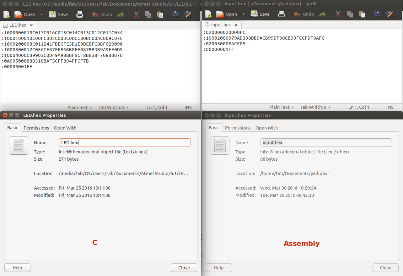
Next I want to try the code to light the led when switch is pressed. I have tried this code in C and now i am writing the code in assembly and lets compare the size of the hex files.
;led connected to porta 7
;switch connected to porta 3
;switch work in active low mode


.device attiny44
.org 0

sbi DDRA,7		;set the 7th bit of DDRA, means made the 7th bit as output
cbi DDRA,3		;set 3rd bit as input
sbi PORTA,3		; internally pulled up the input bit

main:			;label the main loop

SBIC PINA,3		; skip the next line if the 3rd bit (input) is low
cbi PORTA,7		; clear the 7th bit(output pin), means digital low at output pn
SBIC PINA,3		;skip if the 3rd bit is low
RJMP main		;jump to main
sbi PORTA,7		;set the 3rd bit ,means digital high at output pin

RJMP main		;jump to main
Here is the asm file and hex file
Now lets compare the size of the hex file when it is written in c and in assembly.