Week 6: Electronics Design
Assignment:
- Design a electronic circuit board with atleast one led and button
- Show how it is done with words/ images/ screenshots
- Include orginal design files
- Simulate the board
Before starting off with trying different softwares, let's begin off with getting to know about different components that goes into the circuit. Assignment being redraw the hello world circuit with atleast a button and LED. Let's begin off with these components. On the milled boards we generally use SMD components (surface mount ones), in case our component is through-hole ones (those that have legs) we mill a hole and then mount them.
The hello world circuit is already stuffed with Microcontroller (ATtiny 44), 20 MHz crystal oscillator, Ftdi programming header connector and 6 pin fabISP header. The ATtiny 44 is a 14 pin microcontroller, which has Vcc, GND, Reset, Digital and Analog pins. I'm connecting button over pin-6 and LED over pin-5. Make sure you place the LED aligned well (remember the dash goes to the ground).
Some software's I tried out:
123D circuits
This could be the perfect place to start electronics designing for beginers where we could learn electronics and arduino programming.
Some Features notable:
- Real Time Simulation: You could prototype and design before buiding the circuit.
- Arduino Programming: It's possible to program and simulate the arduino programming in th editor
- Collaborative Editing: Team work is possible !
In 123D circuits you can drag and drop the components. The components are listed, categorized and described well. Also, you could search for a component. (I found it time consuming to search and find the right components, and later had to resort to other documentations to get to know the correct component description).

Also, toggling between schematic, pcb view is present. Another feature is addition of bill of material list in the 123D circuits which can be downloaded. Good that the designed gets automatically saved online.
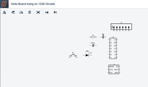
Adding components can be simply done by dragging and dropping.
Schematic view after dragging the components
Fritzing
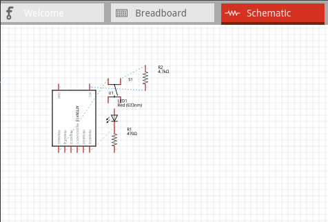
In Fritzing, the components are dragged and placed into the breadboard as below.
After picking up the components, the board
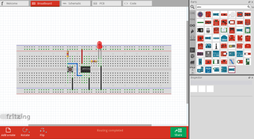
The breadboard after connecting all the components.
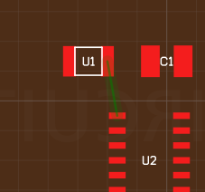
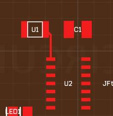
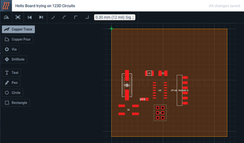
Drawing the traces in PCB
design file of fritzing board.
Eagle
Limitation of the light edition of eagle:
- Useable board area is only 100 * 80 mm
- Only two signal layers can be used (Top and Bottom)
- Schematic Editor can only create two sheets.
Apart from these limitations EAGLE's Light Edition can do anything a professional edition can do. I have been using EAGLE Light edition to develop circuit boards and it seems to be professional yet easy to use.
KiCad
Kokopelli
At FabAcademy, we are turning codes into things. Eagle is just a program that we could use to draw circuits with ease. There's nothing you could program or automate with it. On the other hand kokopelli is pure code and hence it is the closer you will be for turning codes into things. So, Learn and experiment!
Fab academy archives provides a tutorial documentation page for kokopelli, I went through it for learning kokopelli and setting up it in my computer.
Opening Kokopelli
To open kokopelli, use the command :
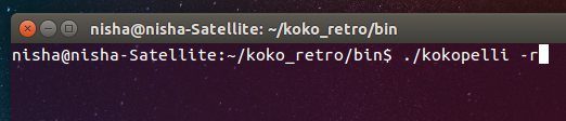
Opening kokopelli through terminal
Changing and adding components using kokopelli
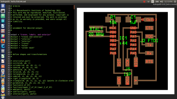
Starting from scratch at such a short span of time seems to be a tedious task, so I started off with a .cad file from Neil's design of hello world board.
The .cad file has around 4000 lines of code text file. It is divided into three main sections:
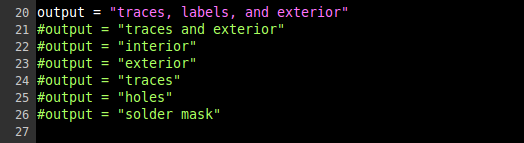
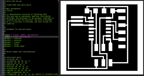
- Section defining the output
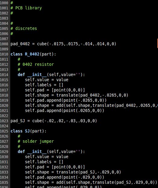
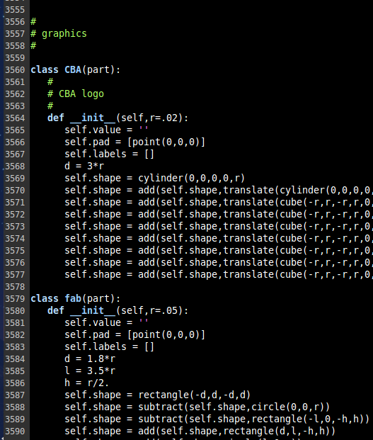
- Section defining most of the components you will need for the circuit
- Section where you could include modifications you need to make for your circuit
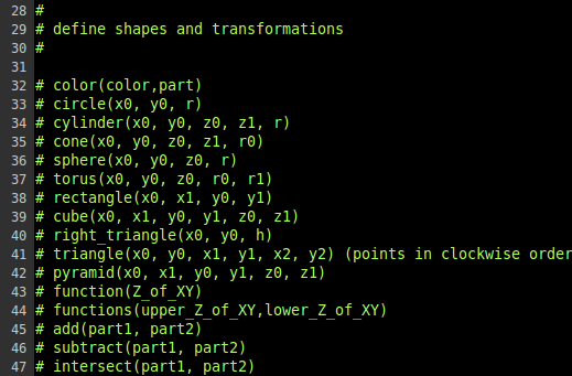
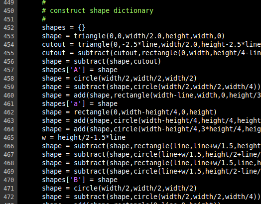
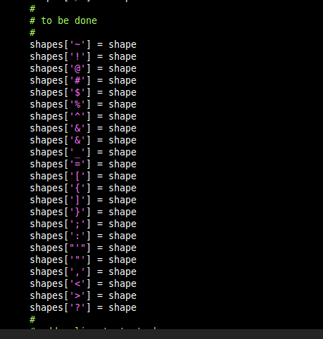
Just to get familiarized with the lines of code, I browsed through the entire 4000 lines. And, It was literally exciting to see code's written to represent the components, alphabets, numerals, etc. Sharing a few screenshots of a few lines of codes
I started by modifying the width and height of the board, so that there is enough room to add my components.
For adding a component in kokopelli, you need to search the code for the definition of the component. That is when I added my button, I looked for button in the second section of the code. The button i'm using is of 6mm dimension. So find the code:
This is the part where you make changes, so to add a unique name for the component you are adding, change the below code:
You won't see any changes on screen yet unless you define the parameters for position and rotation of the component created. The format is:
Here's the screen shot of the changes done to add a LED and a Button.
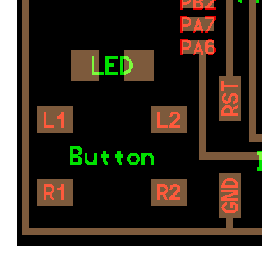
Changes made in coding:
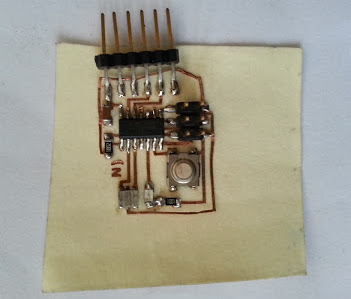
Picture of the Hello World Board I've done
I've done a Hello World Board in ATtiny44 in flexible copper sheet during the week 3. Check out the picture of the board below.