Week 5 : 3D printing and Scanning
This week includes learning more 3D printing and 3D Scanning. We need to explore
through different printing constraints, processes, machines used, different files that can
be sent for print and softwares to design the object to do 3D printing. In 3D scanning, you
need to explore through different softwares and techniques used and scan objects which you could sent
to print.
Assignments:
It's quite interesting week with a good amount of assignments to do!!
Test the design rules for your printer(s)
design and 3D print an object (small, few cm) that could not be made subtractively
3D scan an object (and optionally print it) (extra credit: make your own scanner)
3D Printing
3D Printing also known as additive manufacturing (AM), refers to various
processes used to synthesize a three-dimensional object. Here, successive
layers are formed by computer control. 3D printing can be useful to make
complex geometry's that can't be done. Apart from which I still feel 3D printing is a primitive
technology, there are a lot of things still needing to be met.
Machine at our Lab:
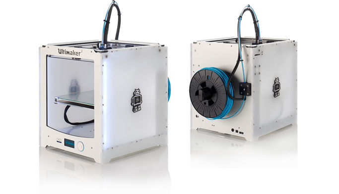
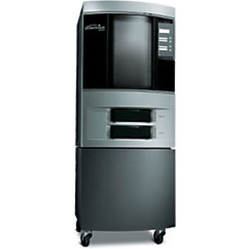
We have two machines at our lab, Ultimaker 2 and Stratasys Dimensions SST 1200.
For the Ultimaker 2, we have PLA plastic spools at our lab. The Ultimaker 2 has a build volume of
223 x 223 x 205 mm all together. The print technology used is fused filament fabrication (FFF).
Stratasys Dimensions uses ABS plastics to make the model and has soluble support material.
It is powered by FDM Technology and can give a print of fine resolution or faster
printing, with layer thicknesses of 0.254 mm (0.010 in.) or 0.33 mm (0.013 in.).
Testing the limits of your printer (Group Work):
3D printing technology can be used to make just about anything. Even a basic
desktop FDM 3D printer should be capable of creating diverse, complex and unnatural shapes.
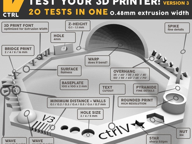
But, yeah way more to go...We used the testfile stl downloaded from thingiverse.com from the link
http://www.thingiverse.com/thing:1363023
Then we print it on Ultimaker with the following settings:
layer height 0.2
speed 50
no support
no platform adhesion methods
The print we got is shown below. (Yogi printed it...we all inspected the test print!)
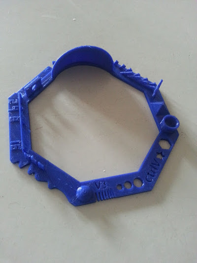
So, this is that small piece of print with some 20 tests all in one piece!!! I decided to check out a few.
Few insights:
- 01 Nut, Size M4 Nut should fit perfectly
There is an M4 nut slot being printed and yes, the Nut fits perfectly
- 02 Wave, rounded print
One of the side has a wavy structure, it's edges looks flattened but, not perfectly round
- 03 Star, Sharp Edges
Near to slot for M4 nut, there is a star shape, whose edges are sharp.
- 04 Name, Complex Shapes
These were not Perfect, some spaces are overlapped. So, these kind of detailing won't be available for
the machine.
- 05 Holes, Size 3, 4, 5 mm
On checking out the size of 3, 4, 5 mm is reduced to 2.7mm, 3.75mm, 4.78mm.
- 06 minimal Distance: 0.1, 0.2, 0.3, 0.4, 0.5, 0.6, 0.7 mm
Minimal Distance is found as 0.3mm.
- 07 Bridge Print: 2, 4, 8, 16 mm
Here, we need to check from which distance bulking starts without support given.
The bulking exists from 8mm onwards.
- 08 Sphere, Rounded Print 4.8mm height
I got a height of 5.8mm along with the bottom layer. That was confusing.
- 09 Sphere Mix, 7 mm height
Height found out was 6.8mm. Okay, that makes sense. Height got affected due to warping.
- 10 Pyramid, 7 mm height
Overall heigh was measured as 6.70mm.
- 11 Overhang: 25, 30, 35, 40, 45, 50, 55, 60, 65, 70°
Slight overhang happening as angle progresses.
- 12 Warp, does it bend?
No, it doesn't.
- 13 Surface, Flatness
Height varies by 0.02mm in different areas.
- 14 Hole in Wall, 4 mm diameter, check for proper print
Not proper in the top side of the hole.
What I find is that, there are constraints for the ultimaker while 3D printing. The
edges won't be as sharp as in the design. So, the best thing you could always do is to
design according to the limitations of your machine. What I say is, Design for your
machine. Design what your machine can do.
Individual Assignments:
To 3D print an object that can't be by substractive manufacturing.
During the Pre-Fab's, I've made strap for my watch by 3D printing. Links of
the strap are something which cannot be made by substractive methods.
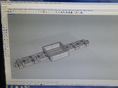
Strap: The strap was a series of chains linked together. My Goal was to print
it as a piece inorder to avoid assembling the pieces individually. I was
pretty successful in designing the chain as such printed using ultimaker
instead of dimensions. I gave enough clearance space between links and the
casing so that the printing doesn't make them stick together. The whole
designing was done using Rhino software. I found it pretty good to toggle
between different viewpoints. The case had a dimension of 3.5cm by 3.5cm.
Initially to check out whether the links are coming up pretty good and movable,
I did a test print of a small section of the strap. I found out that the links
were stiff and needed more clearance space between the links.
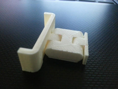 Test cut done to check the link
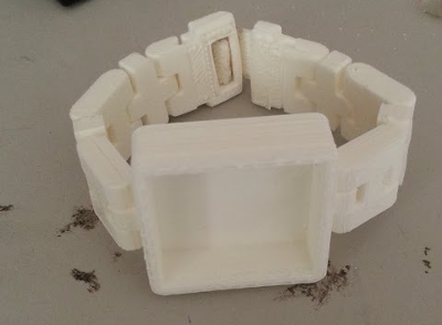 Watch final view
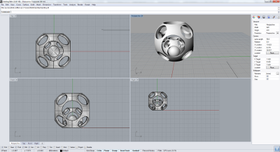
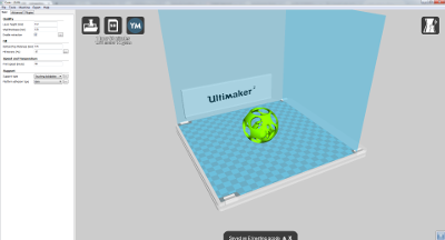
So, I was planning to try out nesting of objects and 3D print them. Sphere
within a sphere was the model I choose to design. I faced a lot of issues while
designing the file in rhino, especially with aligning all the spheres to the
base plane. After designing, I saved the file in .stl format and used Cura
software to create gcode format for ultimaker. I scaled the figure by 2.5 times
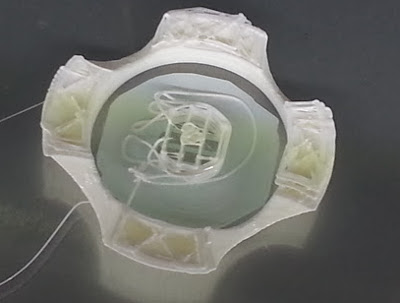
in Cura before printing. At first since I aligned the inner sphere in air,
the print did not come as expected. Which is obvious, you can't print in air. There should
be a support beneath.
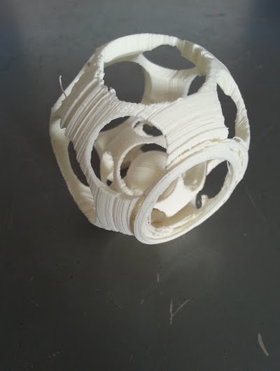
After aligning all the spheres to the base plane, when I took the print since
I did not increase the brim width. The bottom support structure was not enough
to hold the model as it was being build up.
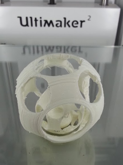
This resulted in a lot of layer being misaligned from the bottom layer. By the
end of printing the model just stripped off from the base plate. Still, I managed
to print the whole figure.
Learnt a big lesson that check out all the settings are done before printing!
 Failure in printing the inner sphere
Design Files of sphere (in .3dm)
Design Files of sphere (in .stl)
3D Scanning
I tried out 3D scanning using 123D Catch mobile app and also using Kinect device.
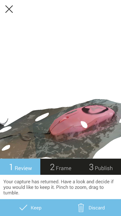
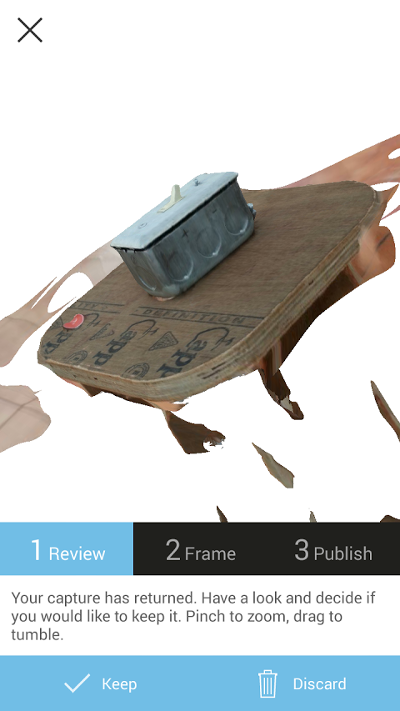
Using 123D catch Mobile app
AutoDesk 123D catch has a mobile app, where you can take the image of the
object and it processes to generate the 3D scan. Just download the mobile app
and capture the images of the object by moving around the object. You need atleast
8 images of the object to generate a scan of it.
I scanned a couple of objects using the app including a mountain dew bottle, laptop mouse, a switch box.
View and download Scanned Files from AutoDesk 123D Link
Using Kinect
Kinect (codenamed in development as Project Natal) is a line of motion sensing
input devices by Microsoft for Xbox 360 and Xbox One video game consoles and Windows PCs.
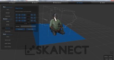
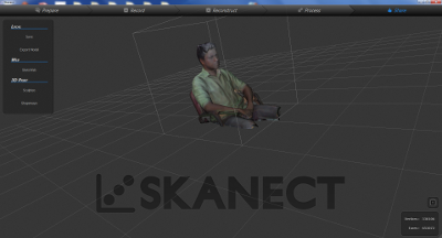
I used Kinect with Skanect to do 3D Scanning. With Skanect, capturing a full
color 3D model of an object, a person or a room is easy.
Some Features of Skanect:
- Instant export to Shapeways 3D printing services
- Instant export to Sketchfab online sharing platform
- Export OBJ, PLY, STL and VRML
- Geometry Simplification
- Precise model editing tools
Tutorials are available at the support page of skanect, which I found useful
while learning how to 3D scan object.
I did 3D scanning of body for my assignment of 3D scanning. Below are the images and the files.
Design File of scan (in .stl)
Design File of scan (in .ply)
Since taking print out of the scanned object is not necessary, I did not take print out of
the scan. "3D printing is not for making figures", Francisco's dialogue!
What I learnt from this week's schedule...
3D printing is that one technique you can use to create objects like links.
3D Scanning, how to do it.
Design for the machine, check for what your printer can print.