Week 16 : Networking and Communications
Assignment :
Design and build a wired or wireless network connecting at least two processors.
My Plan
Networking Method/ Protocols
Basically, there are three methods: Serial, SPI and I2C.
Serial
Here data is send one bit at a time, sequentially, over a communication channel or computer bus.
SPI
Serial Peripheral Interface or in short SPI is an interface bus commonly used to send data between microcontrollers and small peripherals such as shift registers, sensors, and SD cards. It uses separate clock and data lines, along with a select line to choose the device you wish to talk to.
I2C
The Inter-integrated Circuit or I2C Protocol is a protocol that intends to allow multiple “slave” digital integrated circuits (“chips”) to communicate with one or more “master” chips. Just like the Serial Peripheral Interface (SPI), it is only intended for short distance communications within a single device.
I'm using Wired Serial communication
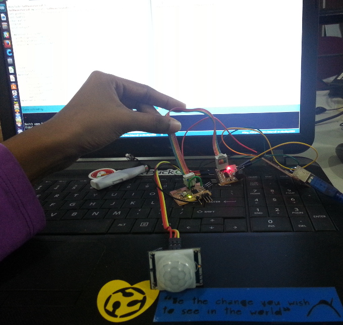
Serial communication is the process of sending data one bit at a time, sequentially, over a communication channel or bus. This is in contrast to parallel communication, where several bits are sent as a whole, on a link with several parallel channels. For this assignment i'm using a node and a bridge board.
Design of Slave Board
I changed neil's board, connected button over second pin and LED over third pin. I also took out MOSI, VCC and Gnd pins to an external connector, so that the board can be used again.
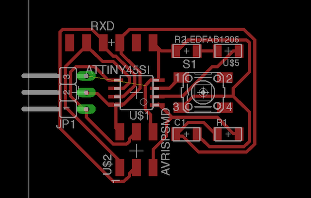
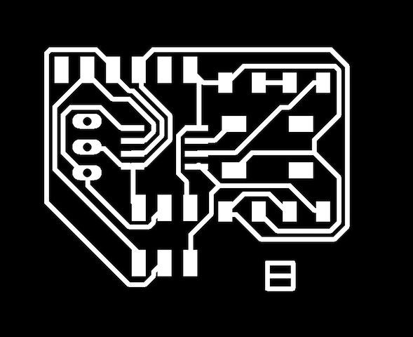
Design File in eagle
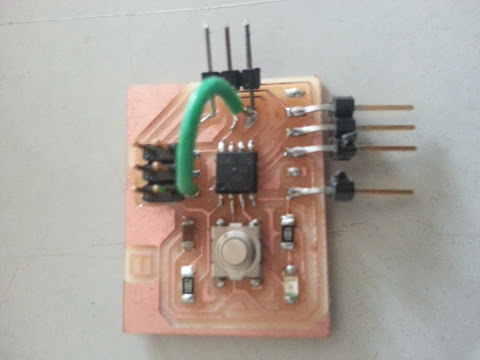
I had a wire not connected in the eagle while autorouting. That was the problem I encountered while designing the board. I added a jumper wire while stuffing the board, which solved this problem.
Programming
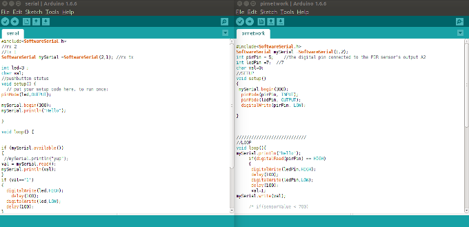
Programming File (.ino)
On programming the boards talked with each other
Even though the boards talk to each other, what I was missing was the device ID. Device ID sets the identity of the board. So, you can add any number of node board and the node board whose ID called shows the output. I modified the code as below to achieve this.
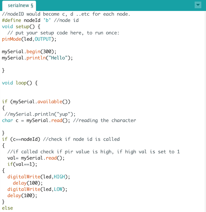
Now, only when the node board is called, it checks for output from the bridge board and then shows the output. From the computer we are sending a message in the serial communication channel. This message is the name of the node, both the nodes listen to it but the one board whose name is the called responds by blinking differently.
Programming File updated(.ino)