What are we trying to do?
Make something big, and in the process learn computer controlled machining with Shopbot CNC machine.
Inspiration.
I wanted to do a form of the chair that would have curves for ergonomic purpose and it would be as continuous and smooth as possible. I had other big idea which was to make a reclining chair like the office chair but the designing process was taking so long I had to stick to a much the first version or a part of it which is the layered chair. I took inspiration from Dyvikdesign.
They use glue the layers together. In my version I would try to use a beam to support these layers.
I couldnt make a great design for it as well as it could take a lot of time. SO I decided to roll with a decent design that would be like a demo for later much better deign. So The curving was to be introduced and the current design should prove that the curves come well with this method and it should be structurally sound.
Plan.
I will create the form from any of the 3d modelling softwares and export stl file from it. I will use Autodesk 123D Make to slice them into layers and add notches and interlocking features.
Execution.
Autodesk fusion was in my mind but I was n Ubuntu and the only decent solution for ubuntu would be Onshae which was based online. And so I started with Onshape to make the design. I found Onshape very similar to solidworks but much lacking in features as compared to Fusion 360. A couple of steps into the designing I was finding it difficult to use it further to get what I wanted. I wanted to create extrusion from an edge of the solid model and I couldnt find the way to do that. I tried googling for a solution and later thought of moving on and trying out a different software rather than waste more time on this.
I switched to Rhino(and Windows) for designing now. Rhino was an instant hit because I was very easily able to manipulate any edge or surface that I wanted and googling gave a very precise solution to whatever I was looking to do in Rhino.
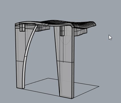
I first created this form in Rhino. I was trying to create the entire chair but as I was moving forward I realised that only half the chair was required to generate manufacturing files and the mirror image could be used to create the other half.
Useful commands- Sweep1, sweep2, dupedge, trim, extend, extrudecrv, extrudesrf, booleanUnion, booleandifference, cap.
.
The idea was to use 123D make to slice them and get the plans, I wanted to use interlocking technique so that it automatically generates the notches I require to interlock the beam and the seat. It didnt work as good.
Rhino design final.
 .
.
Problems and learnings.
Getting the slicing direction right was a pain in 123D make, so I had to go back and reorient the model according to the default slicing direction which is z direction.
interlocking didnt work very well, because I cant control the size of the groves it is creating and if the groove is deep it will make the plywood structure weak. Also it doesnt work great with the beam inside the slot. I cant ask it to take the entire beam as one structure and use it, it tries to split the beam into two parts, making the beam weaker
So interlocking didnt work, stacked slices technique slices the model and makes provision from dowels to be attached to locate position the slices wrt to each other. So stacked slices without the beams worked the best to generate plans. Stacked slices dont generate groves etc but it does output and stl file with the slices and of each slice as well. I decided I will use this stl with sliced layers and and create groves and a beam suitable for them in the rhino. Luckily Rhino can also edit meshes.
123D Make, slicing.
 .
.
This turned out to be a messy job, I performed th following steps in rhino
Mesh Editing.
 .
.
Initial prototyping.
 .
.
I scaled down the figures so that the slot are of 3mm thickness. And removed the legs and nested them.
I decided to go further in straight forward way, that is use rhino to slice stuff and create stuff that i require, no more messes with meshes. What I found out was that this method actually the easiest way to get what i wanted.
I was trying to make my job easier but kept ending up making it more difficult.
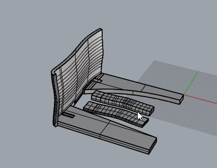
So now I tried using the splitting option provided in Rhino, split the model at multiple of 19mm(plywood thickness) and exploded them and preserved only these surfaces

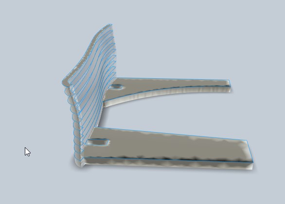
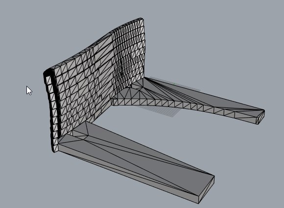
Here is a side by side view of extruded solids and the original layers.
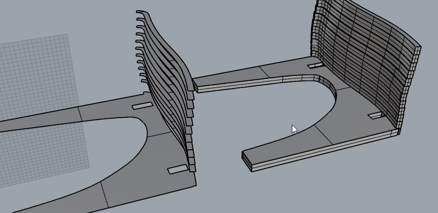
I created new solids by extruding each of these into solids of 19mm The I created the beam as straight extrusion from the hole in the leg of the chair. Using the solids created as the seat surface the beam extrusion was cut. The resulting solid body was moved into the seat for about 3mm and the layers of the chair was cut with this solid, this created the interlocking. I later filled remaining that the moving created by adding new solid appropriately.
I further extended the beam and added some slots that into which a peg will go. The peg will ensure structural stability in the lateral direction.
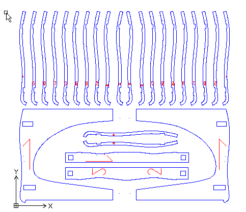
Now that I had the proper solid model. I went back to 123D make and sliced again. This time everything went smooth and it generated dxf files. I generate slices for the beams different from the chair. When i had all the slices I nested them inside one file.
By this time I so wanted to be done with machining I forgot taking screen shots of the machining process an settings, But the following is the workflow I usually follow.
Toolpath Generation
Select outside features and create the toolpath with following settings.
Saving tool path- Save the drill operation in a different file. proceed with saving inside and outside toolpaths such that inside feature come on top and later the outside features.
Machining in Shopbot
We have PRS Alpha Shopbot with us in the lab, an absolutely pleasure to use except that the software crashes often while perfoming jogging operation in order to position the spindle.
I broadly see where my zero would be and how can i place and position the wood for the cut.
I set the plywood on the bed and screwed the plywood with wood screw on the corners and the sides with around 2 feet gap between each.
Then I move the spindle manually while the machine is off, in order to position the spindle where I want with my hand. Its hard to do this with good dexterity while using the machine. Since clearance were tight here I had to take the manual way to position it. When I was satisfied with x y z zeroing, I switch on the machine and select this position as my x y and z zero.
I proceed with cutting by first selecting the drill operation files. and proceeding the cut. Once the drill operations are finished, I locate the half drilled pockets and drill them further a litlle with 4mm drill and then use the wood screws and the screw driver drill to fasten the plywood in these locations. Of course the gantry is jogged else where for comfortable operation on the job.
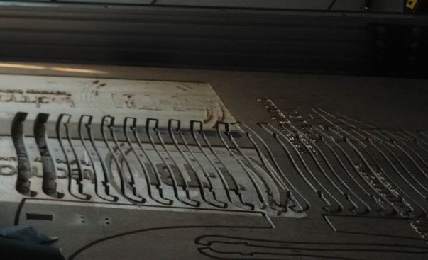
The Rest of the tool path is loaded and is cut.
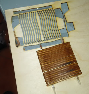
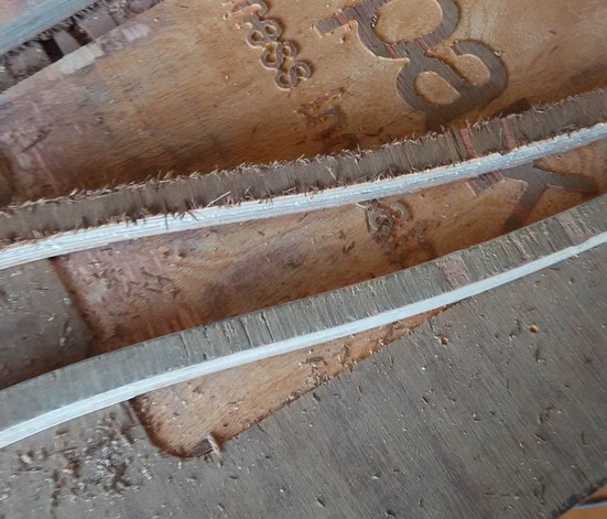
The cuts came pretty good.
I used a sharpie to write numbers to identify different slices.
later each piece were sanded by sanding paper.
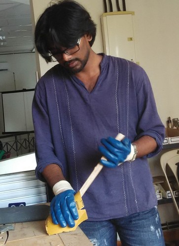
Sanding makes a lot of difference for further handling
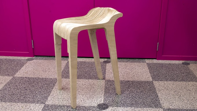
Heroshot- Layered stool
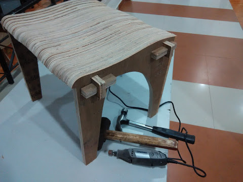
And Me
Download Design files for Rhino Software
Download Dxf files for cutting