There are vast possibilities 3D printing offers which the subtractive manufacturing processes can not offer. Since the model is built layer by layer lot of interesting possibilities arise from the physics of building things layer by layer. such as the ability to build a complete 3d shape without blindspot as compared to 2.5D capability of conventional milling process, interlocking feaures, true hollow objects, nested objects etc. Different 3d prining techniques are able to offer different solutions and capability to create complex geometry. We have an Ultimaker 2 in our lab which works on FDM technique. Even though possibilities exists there are cotriants and boundaries this technique and machine offer us. We used the testfile stl downloaded from thingiverse.com from the link http://www.thingiverse.com/thing:1363023 and tried to print it on our printer with the following settings.
layer height 0.2
speed 50
no support
no platform adhesion methods
The author points out the following criteria and features to be tested. My conclusions follow.
3D scanning tools and creation and editing solutions are not new to me but its the first I am going to try to use them in a more serious fashion.
I found this when I was searching for open-source alternative for autodesk catch. This does pretty much the same job as autodesk catch. Here is an interesting video with instructions on how to use it.
https://www.youtube.com/watch?v=D6eqW6yk50k
https://www.youtube.com/watch?v=V4iBb_j6k_g
I installed VSFM on windows based on the instructions given in http://ccwu.me/vsfm/install.html.
The basic idea is to get a lot of pictures each from a different of angle, run a image feature detection algorithm, match the features from different images and make relations, guess the angles of the camera and the distance of the objects and features from the camera from the pictures used and try to put together all of them in a point cloud that satisfies the constraints and guesses.
Fot this experiment I'm going to attampt to scan an electric kettel.
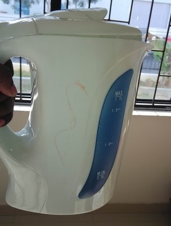
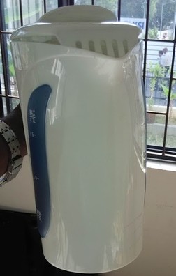
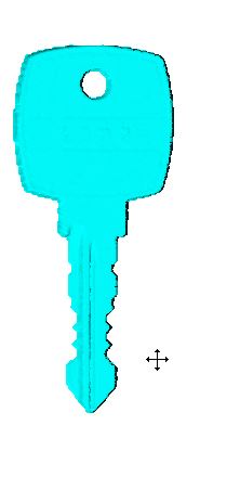
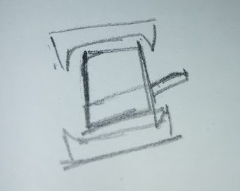
Tips - Shiny or transparent objects dont work well with this method. You own shadows can cause confusion for algorithm so taking it under bright lighting conditions is good(lighting directly shown to the object taking shadows away from the photographing space, the lesser difference in individual angles the better(in case you are taking a video, move slow), Symmetrical surfaces without any features to distinguish each area are not processed well for example a plain colored cylinder, in order to solve this try to keep markers around the object or draw something on the object itself, I drew some sketches on the plain faces of an electric kettle which I tried to scan using this method.
I found that the process of the getting the images is too laborious if you want to do it shot by shot angle by angle, it can be simplified if we took a video of the object circling around and focusing on it and try to go many circles around the object, try to cover all the angles. Now images can be extracted from the video at short intervals of time. There might be tools that directly use a video as input but they are below radar now.
I used KMPlayer in windows to extract the images every one second of the video I took. Right click on the video and select menu 'Capture', here choose 'Frame : extract', set relevant options(there multiple ways you can capture frame, I selected to capture one frame per second) and start the capture and play the video.
I followed the steps given in (http://ccwu.me/vsfm/doc.html) under basic usage to generate a dense point cloud. This I imported the generated ply format point cloud to meshlab(http://meshlab.sourceforge.net/) cleaned up the mesh. -Deleted the unwanted points cloud. -Compute normal to point set(Filters->point set->compute normals for point set) -Use Poisson surface reconstruction algo(filters>point set->Surface reconstruction: Poisson) -Clean the mesh, delete unwanted faces and verticies. The mesh that came out was not of good quality. We might have to do some more editing on the mesh for it to give a meaningful output. I think it was because I used a shiny object.
Autodesk catch gave a excellent mesh for the same data.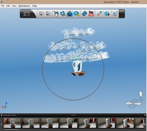
I uploaded the pics, waited for processing(it does take a few minutes).
Export the mesh as obj(Doesnt provide stl option)
When opened it in meshlab to check the mesh this is how it looked.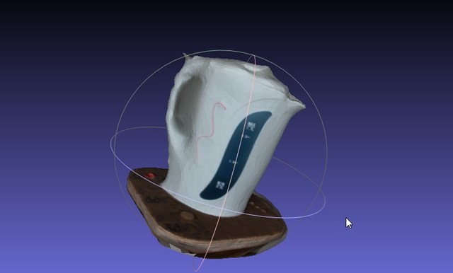
Since the object was a shiny one the methods didnt a very accurate model but autodesk catch was the simplest to use and gave a watertight mesh right of the bat.
Usually a low res mesh is created from Catch. In order to get Higher res you select generate mesh and choose from the 3 options you get. During highres mesh generation the colors couldnt be created properly but the mesh looked better pic
Both werent able to capture the handle feature of the kettle correctly.
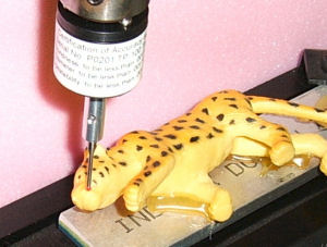
How contact probing works is the machine will have a mechanical probe that is attached to a mechanism (gantry of arm) though which accurate location of the tip of the probe can be accurately calculated. The probe is a switch that gets activated when it comes in contact with an object and gets pushed and at this trigger tip of the probe is calculated from sensors and registered.
source(http://www.imsrv.com/deskcnc/probe.htm)
A Ruby tipped Probe for heavy duty applications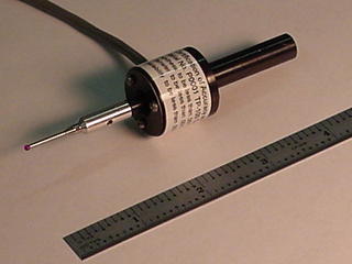 source(http://www.imsrv.com/deskcnc/probe.htm)
Comparison
Unlike photogrametry contact probing is highly accurate, since its not based on guessing but actual measuements. Photogrametry tools use probabilistic theory in order to arrive at best approximation. photogrametry hence have very less use in engineering and more use in fast approximate capturing. But mechanical probing takes a lot of time and is limited by machine reach movements.
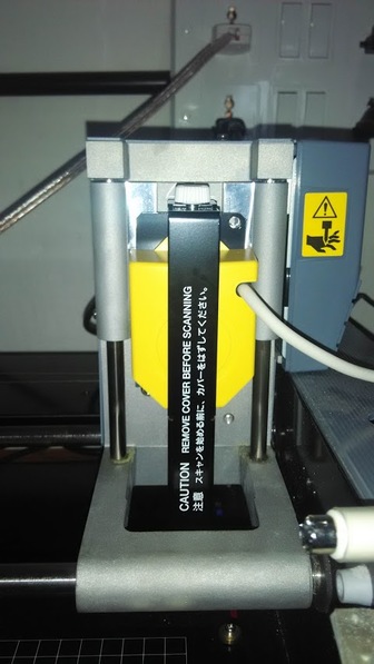
Roland Modela has a scanning attachment that is uses contact probe as its sensor.The Roland Modela probe looks more like a needle and is meant to handle smaller objects. This probe is sensitive to fewer grams of force than industrial probes.
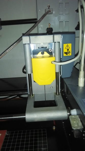
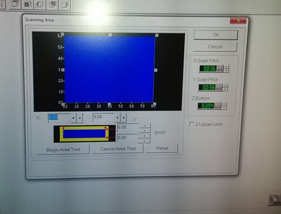
Check "Z- Upper limit"
Max size of the object you can scan.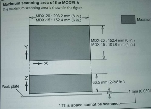
7.. select ect x-pitch min z and y pitch. Pitch is the distance at which the z coordinate meaurment is taken. 1mm pitch means every 1mm the probe takes measurement. Start scan. You might see the machine moving wildly from one extreme to other extreme. Dont worry the machine is trying to get a feel of the size and shape of object it is handling. Then the regular probing per pitch distance continues.The machine movement and probing algo is pretty robust.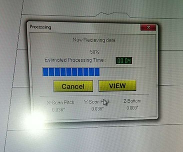
Mesh using higher pitch distance (0.038 inch)(less detailed)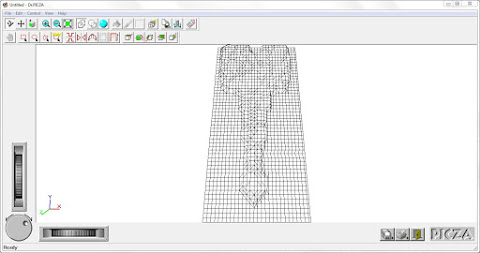
Mesh using lower pitch distance (0.010 inch)(higher detail)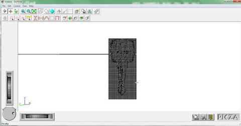
(Apologies for unequal zoom)
8.. After the scan completes mesh is generated form the pointcloud recorded. Try out different features Picza has to offer. There are some interesting features for model editing. You can mention custom dimensions here. and do some minor adjustments to the mesh.
Render option
I was inspired by Neil's mention of assemblers in the 3d printing and scanning lecture. So I tried to build a concept model in that line f thinking.
Idea: Zipform2D
The whole of the idea is having a chain whose individual blocks can be oriented and locked in positon in space wrt the previous block and a machine that makes a part or structure by locking chained blocks together.
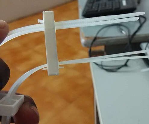
After much ideation and consideration of time that I have to design and the material and techniques available in fablab I thought of an assembly using zip ties(the head of the zip tie and the rail separately) that can be oriented in space and locked in space.
Required materials and machines
You will need a zip tie that allows you to open it back with a tiny lever that is easily accessible, Knife and 3d printer.
I took the measurement of the zip tie head. This will be held in place tightly by snap fit like feature. The zip tie head was approximated to a cuboid of 7mmx8mmx5mm.
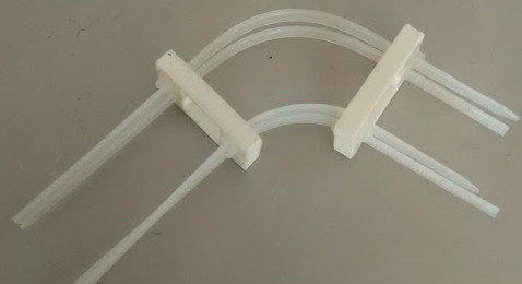
There are two parts of the assembly here, the car- holds the ziptie heads in place and the rail- the zip tape.
In normal circumstance the car is constrained and cant freely move through the rail.
When the lever of the correct zip tie head is pulled, the rail can move through. And when the lever is let free the structure remains in that configuration. So you can create a bend you like and it will remain in that configuration. You choose the distance between the cars to adjust the rigidity(or flexibility) of the structure. Essentially You can create bends and play around with rigidity of the structure.
Design process
I used Antimony to create my design. Antimony has an option called clearance which generated a thin offset cut from the surface of the rounded cube I created mimicking approximately the volume of the zip tie head.
I created the volume of shape of the zip tie head and created a volume covering it with some thickness I applied clearance CSG operation in between these two volumes and using difference CSG operation negated the zip tie volume from the resulting object.
Then went on and created copies of this feature and located them where I required. And located and created the features that joins all of them together(intersecting them for now later when union is applied it merges all).
Using union I conjoined all the volumes together and using export node I output the resulting volume in stl. and printed in in Ultimaker2 with the following settings. I had to orient the model in a way that would give me the best output, minimum overhang.
Layer height- 0.2
Speed- 50
no support
no platform adhesion
Why Additive manufacturing.
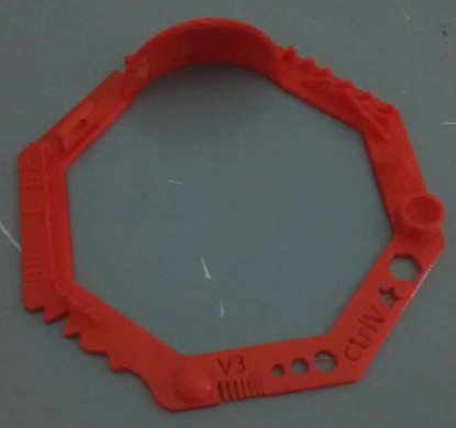
You might not be able to see it clearly in the sketchfab preview but if you zoom in enough you will see that the small hollow holes have lip kind of feature. The idea is that the object that comes inside that will snap fit into place inside the hollow. The Additive manufacturing technique and especially 3d printing was the best alternative to create this because I needed a specific feature inside the volume. Here I have a hollow space but there are some functional feature inside the hollow space to enable snapfitting. The object is small and feature are also very tiny. the scale of the object and its 3d features makes it very difficult to be created in a subtractive manufacturing process.
The object was created in antimony. You can try to understand it and modify it to the size of zip tie you want to use.
Assembly