Out if many project ideas considered I chose to develop the CNC with wheels concept.
This will involve building a chasis, Gantry sytem, Networked Stepper motor driver and networked proximity sensor.
I will simulate the working of the mechanical system and motors using RAMPS shield on Arduino Mega.
I will check the working of the stepper motor driver and proximity sensor on network.
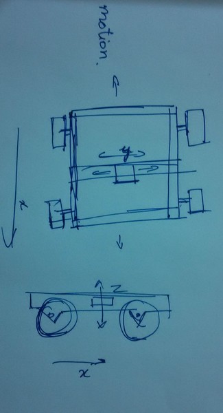
The mechanical system contain the following systems and sub systems
X-Axis/Linear Stage/Gantry
The gantry has the following systems
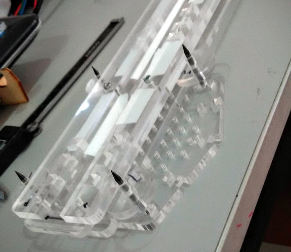
- Linear Slide - The acrylic is cut in required shape and assembled in proper manner. It constitutes 3 layers of 6 mm laser acrylic plates assembled such that a groove is formed. These are the grooves on which the wheels will roll for reducing friction and be constrained for linear motion.
Download linear slide dxf files
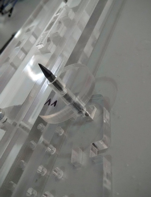
Sliding Block - Constitutes acrylic wheels, shafts to hold the wheels also to act like bearing, the plates to hold wheels and shaft and to mount end effectors and the snap fitting locks to hold the plates together and different set of snap fitting to hold the shaft from moving side ways.
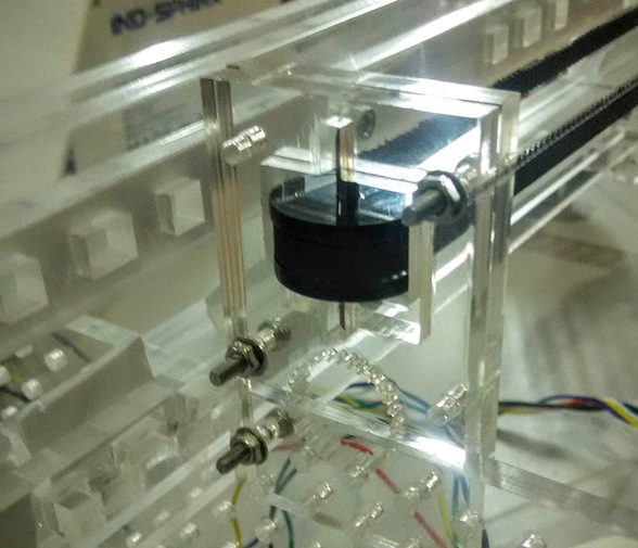
Download sliding block assembly fiesPower and Transmission system -The power and transmission sytem constitute of the motor fastened at one of the slide, timing pulley prototyped from laser cut acrylic sheets(32 teeth acrylic timing gear coupled layers of 3mm acrylic to host a nut drive a screw to hold the motor), Timing belt that goes over the timing pulley, and acrylic timing pulley similar to timing coupled to motor but instead here it would slide over 1/8inch shaft and act like a bearing.
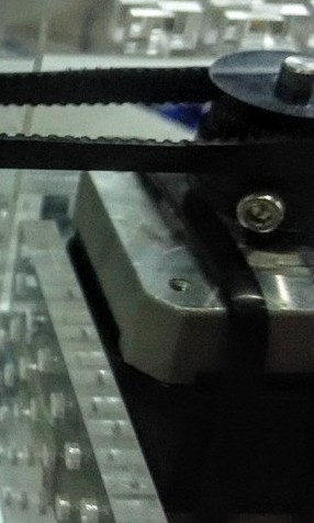
A section of motor coupling
Timing pulley block coupled with motor
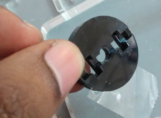
Freewheeling/ sliding timing pulley
Download drawings of Motor coupled gt2 pulley components
Download drawings of 1/8inch hole timing pulley
Download drawings of 1/8th inch shaft holder for the pulley
Download drawing of shaft holder positioning.
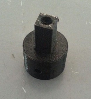
3D printed couplings.
The bonded acrylic sheets aren’t that great to handle forces of the fastening of the m3 screws. If too much force is applied the whole thing might come apart. Therefore A 3d printed solution is better. The 3d printed coupling will look like the following. It was created in onshape. I searched for ready made designs of nema 17 motor and made the assembly.
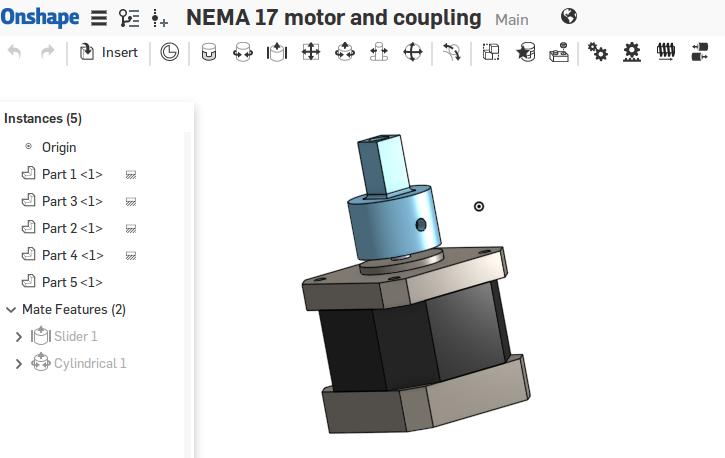
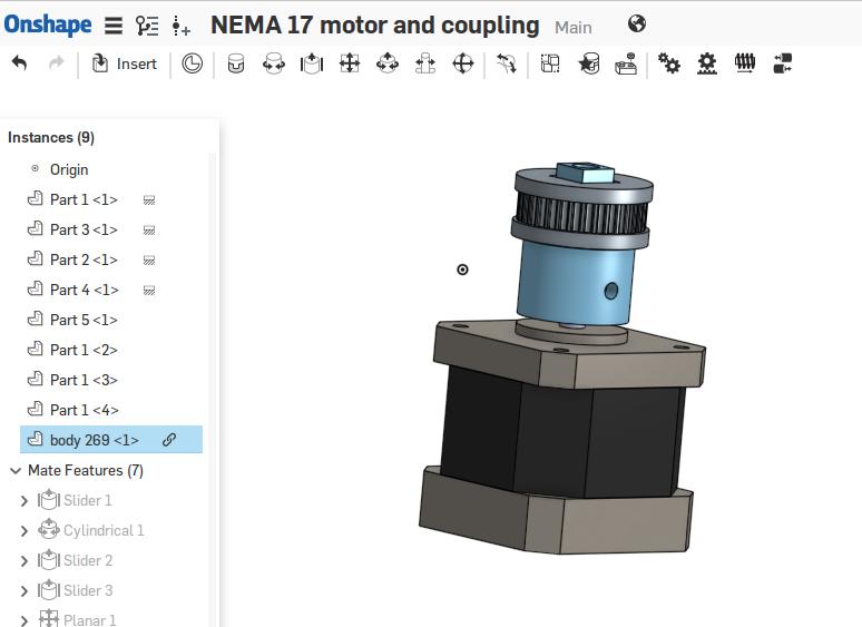
3D printing part
The design can be found on Onshape
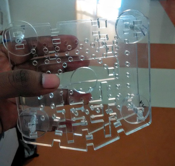
Chassis.
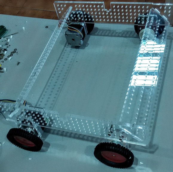
The chassis will be a pressfit construction using 6mm Acrylic. It will have mounts for mounting free wheels and motors and slots for mounting the gantry. The wheels are bought out from the shelf and are very cheap fabricating the wheels would cost much more.
Download Chasis files
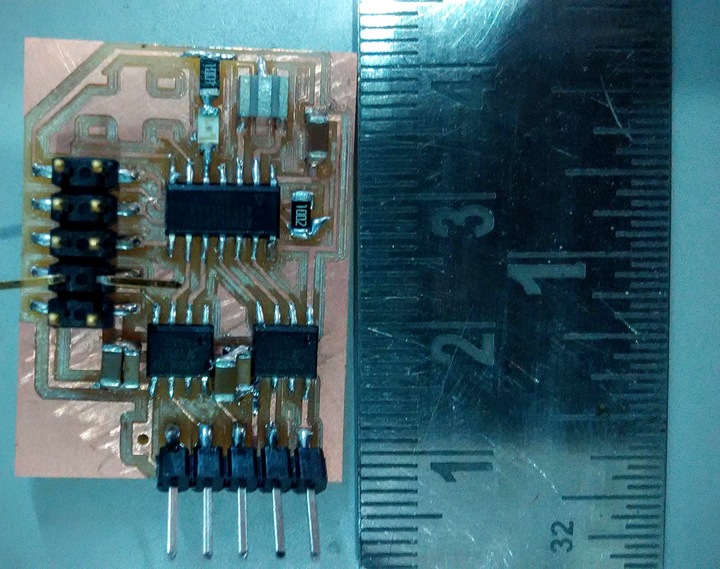
The stepper driver which I’ll be designing will be based on Neils half bridge stepper driver board and hello board. I’ll be adding half brdige ICs A4953 and n LED and a button to the hello world board. The FTDI will be removed, The ceramic resonator will be retained, I will be reusing some pins of ISP connector for serial communication. I have added 5x2 pin smd jumper to accommodate, combined functionality for ISP programmability, serial communication and 12v Power distribution. To achieve all this in one I had to hack the 5x2 pin jumper and create special ribbon cable with 5x2 pin header for serial communication and power distribution. the ISP connector could be connected to it for programming purpose in regular fashion.
Design
There was a mistake done here. I forgot to add the 0.1uF and 10uF capacitors in parallel for the each of the power supply line VBB of the A4953 ICs. I later corrected this in my board.
Design
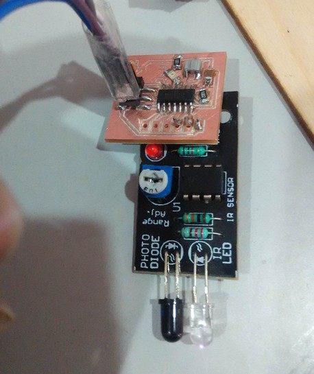
I will be attempting to make the stepper motor work over a network and get inputs from the infrared sensor.
Stepper motor working from network through serial
Proximity sensor sending output to the network through serial
Problem
The network stepper driver and the infrared sensor work well individually. However wjen I share the rx tx across the network the computer stopped receiving from both the boards, but I was able to still control the motor. I do not use a bridge board here nor do I use the FTDI cable. I use a FTDI breakout board and connect all the rx and tx together. Debugging in progress.

Improvements
Make Linear slide modular, make an acrylic rotary stage, Improve precision.

Infinity CNC by Puneeth Raj J is licensed under a Creative Commons Attribution-ShareAlike 4.0 International License.