Computer-controlled Cutting
Overview
Last updated: 22/02/2016
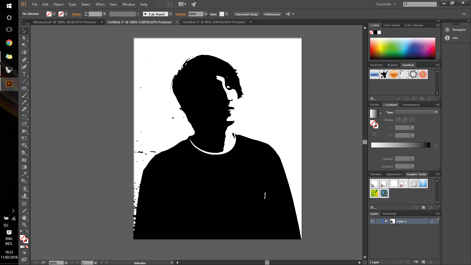
Objective Design and make a corrugated cardboard press-fit construction kit. Learning outcomes 1.Demonstrate and describe parametric 2D modelling processes; 2.Identify and explain processes involved in using the laser cutter; 3.Develop, evaluate and construct the final prototype; Have I... Explained how I drew my files? Shown how I made my press-fit kit? Included y design files and photos of the finished project? Summary The week started with understanding how a drawing software interfaces to a cutting machine. From either the vectors or the rasters created with the CAD tool, a text file is generated where the movements of the machine are coded. Formats differ quite a lot, and some need a proprietary software to be generated. In sequence, this page reports the work I did with the vinyl cutter and the laser cutter.Vinyl cutter Using a Roland GS-24 I cut a sticker of myself, which might sound a bit selfish. It actually is. After I had traced a picture in Adobe Illustrator, I exported it as a .png with a resolution of 1000 dpi.
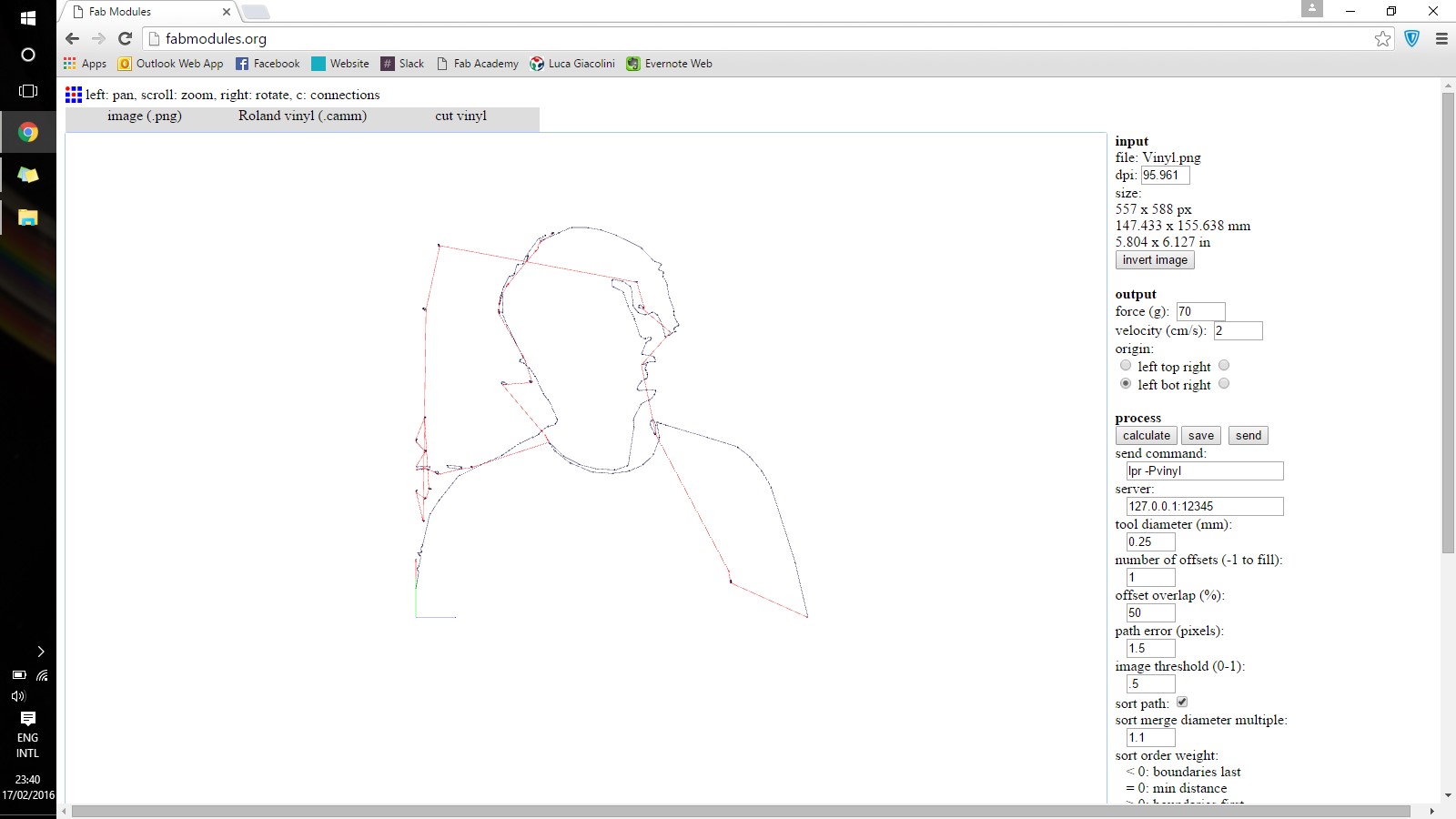
 After that, I opened the Fabmodules where I uploaded the file. In the settings I put power to 70% and speed at 2. Eventually I got a .camm file which I saved on my home directory [1]. The Roland GS-24 head can move electronically to set the origin of the print.
 From the terminal I launched the following commands in order to send the job to print using the built-in driver in Linux.
dmesg to check whether the lp0 is recognised
        cd directory of the file
        su
        cat filename.camm > /dev/usb/lp0
Laser cutter At the lab we use a TROTEC Speedy 400 that has a surface of 600 x 1000 mm. It is equipped with both a CO2 and a optical fiber laser. For the explorations reported here, 6mm cardboard and the CO2 lasers were used. The file to be executed needs to be prepared with the exact colour coding (in general red for cutting lines and black for engraving) and the right line thicknesses (0.003pt for cutting). After that, the vector file gets uploaded to the machine driver software which allows the manipulation of 3 parameters before executing the job: material thickness, cutting speed and cutting power. Even though there are quite reliable preset configurations, it is better to empirically come to the perfect settings. As a starting point Matteo set up a test piece where to try out different modes of cutting. Eventually, we came to the conclusion that cutting the cardboard at 48% of the power and 1% of the speed delivers the best quality and precision.
Concept: Marble Machine Kit For the assignment I decided to build a lo-fi marble machine that consists of a grid where several modules can be located and moved around in order to create a path for the marble to slide. I decided to follow this route because it seemed to allow me for three types of explorations that I wanted to do: 1.female-to-female press-fit mechanism; 2.female-to-male press-fit mechanism; 3.pattern for curved surfaces;
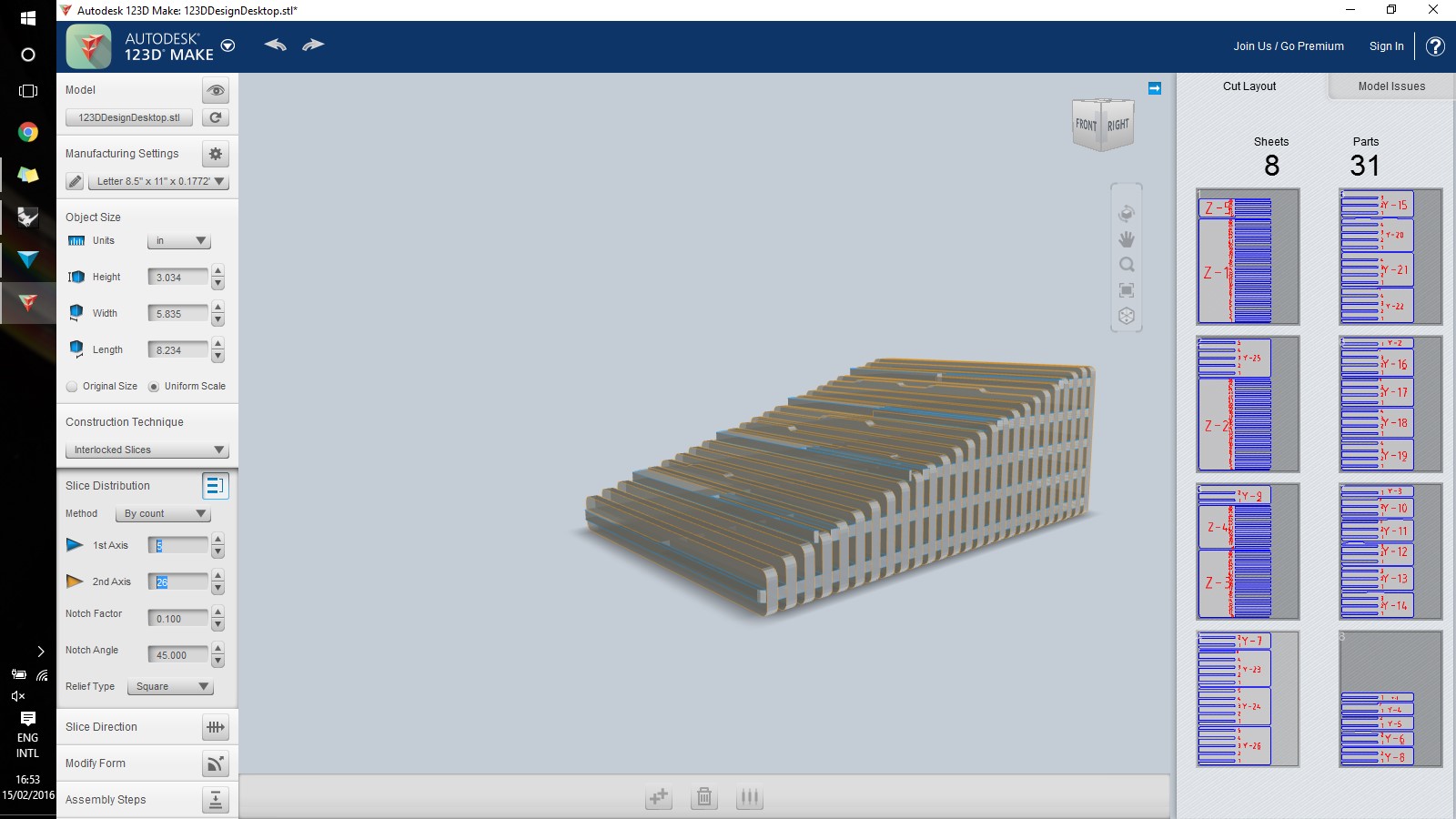
123D Design First thing that I did was to try to visualise it with the software 123D Design, just to learn a new tool [2]. I did find it quite difficult at the beginning because I am quite familiar with Solidworks where you have instead to base your geometries on planes. 123D Design connects to 123D Make which is a really cool software that translates a solid geometry into a sliced object ready for the lasercutter. You can control the amount of layers, their distances and the thickness of the material. Eventually, even though this (free!) software seems quite promising for quick studies, I realised that the shape I had in mind could not be represented properly. I think that 123D is fine only when you want to lasercut solid objects. However, It is pretty useful that it even makes the nasting for your 2D drawings!
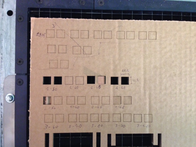
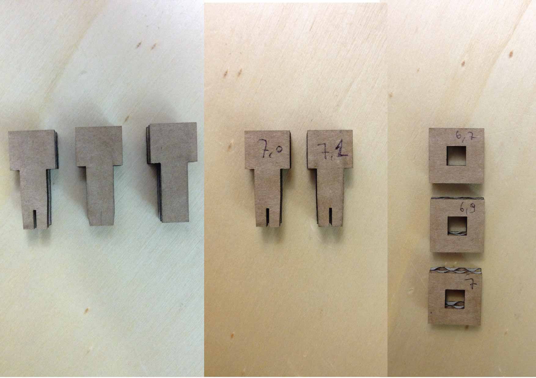
Press-fit tests I started with testing male-to-female types of mechanisms. The picture below shows different male bits on the left. They are all designed to fit in a squared hole. After the most promising was chosen, due to its malleability at the tip, I went on with considering dimensions. The kerf of the cardboard cut is actually little significant. According to empirical measurements it varies from 0.05mm and 0.1mm. The first tests pieces were designed with the kerf in mind. Then, also considering the soft nature of the cardboard, I decided to actually decrease the hole dimensions of almost half a millimeter with respect to the official calculations. In fact, the 7.1mm male piece fits perfectly and tightly in the 6.7mm female part.
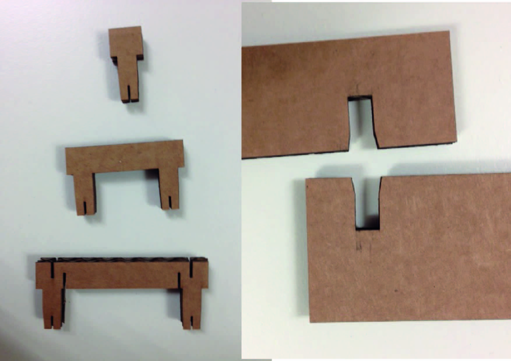
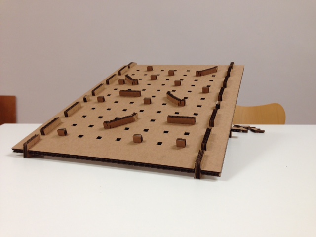
 The picture below shows that I have three modules for the final prototype of the marble machine [3], which makes it a modular project. After the studies I made with male-to-female joints, I also studies female-to-female connections. As shown on the right picture I used them to build the basis of the sloped surface. They are both of 6.5mm. Furthermore, I also managed to design a module that can bend in two points (after I had burned a couple, though!).
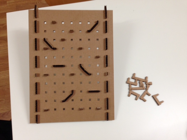
Illustrator Drawings The final work is shown in the two pictures below. All the drawings were made in Illustrator [3] as a preliminary work. The prototype is solid enough to allow marbles to run down the slope and allows for a certain level of flexibility. However, I wish I had made the grid even bigger, so that I could extend the routes even more!
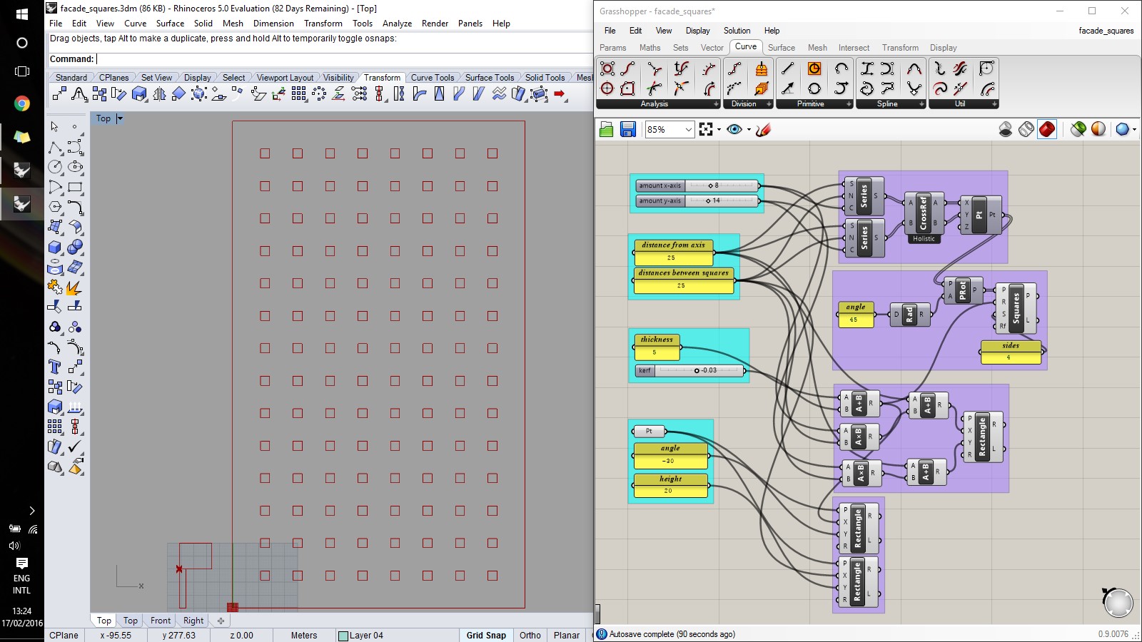
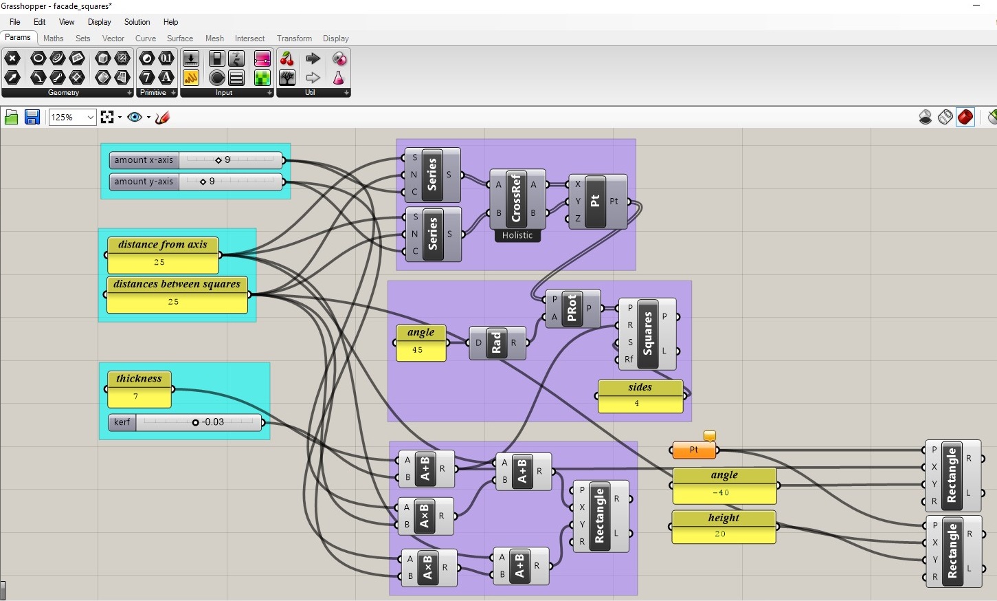
Grasshopper After I had made the prliminary drawings in Illustrator I started to use Grasshopper in order to do it in a parametric way. In the patch I designed there are several parameters that can be manipulated: 1.height and width of the matrix; 2.thickness of the material; 3.distance between the squares; The patch can be found at [4]. The sketch is both parametric and generative, meaning that nothing but a reference point is actually drawn in Rhino. The picture below shows the resulting grid and male piece on the left, while the patch is shown on the right. In the patch, the light blue groups are for entering variables, while the purple ones represent the actual drawing functions.
Conclusions Even though this should have been an "easy week" for me, I managed to challenge myself when I decided not to use SolidWorks to do parametric design. Exploring both 123D Make and Grasshopper turned out to be successful. Antimony turned out to be too challenging for my visual-oriented way of working, even though I would still like to give it a go in the future, maybe. Overall, I simply really liked Grasshopper. As for machines, I learned that the laser-cutter allows for many cool explorations. In particular, the one that we have does mount also an optic fibre laser which can engrave metals. To conclude, I liked that I launched a job to print from the shell, without using a driver.
Table of Content
Resources
- [1] Vinyl cutter file
- [2] 123D Make file
- [3] Illustrator file
- [4] Grasshopper patch