#Exercise_8
16/03/2016
Assignment
Embedded ProgrammingRead a microcontroller data sheet Program your board to do something, with as many different programming languages and programming environments as possible.
- Identify relevant information in a microcontroller data sheet
- Program your modified Hello board
For the assignment I have decided to program my version of the Hello obard developed in the 6th week. The board have two leds, one red and the second one green; so the behavior will be the blinking of the green led when the button will be push and the blinking of the red led when the button is not pushed.
I'm used to the Arduino environment and language, so I have decided to experiment directly to program the attiny with the C language using the Register and AVRDUDE to compile the software and upload it to the attiny 44A. At the end I will try to use the Arduino IDE to program the Attiny44A and compare the performance.
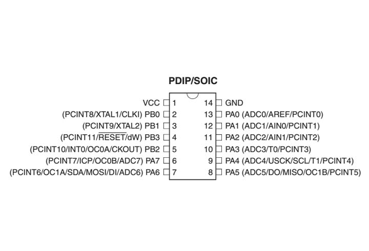
Analisys: The microcontroller selected for the assignment is the Attiny44A an AVR 8bit SMD package. The 44A have 4KBytes of Flash memory (for the program storage), 256Bytes of EEPROM (for data storage) and 256Bytes of SRAM (for data memory). The microcontroller could work at 0 Hz until 20Mhz external clock; after all the 44A have good performances, a low power consumption (operating voltage 1.8-5.5V and 210uA @ 1.8V in active mode) and a very good price.
The 44A there are 12 bi-directional I/O ports with optional internal pull-ups. The microcontrollere have a Programmable Watchdog Timer with Separate On-chip Oscillator too, and an Internal Calibrated Oscillator until 8Mhz is available.
The In-System Programmable via SPI Port
"C" programming with Attiny44A
#include < avr/io.h >
#include < util/delay.h >
#include < avr/pgmspace.h >
1st step: after the lesson of our instructor I started to study the Neil software hello.ftdi.44.echo.c. From here I imported the same libraries in order to use some features in a simple way, like the delay.
Source file
#define output(directions,pin) (directions |= pin) //set port direction for output
#define input(direction,pin) (direction &= (~pin)) //set port direction for input
#define set(port,pin) (port |= pin) //set port pin
#define clear(port,pin) (port &= (~pin)) //clear port pin
#define bit_test(byte,bit) (byte & (1 << bit)) // test for bit set
2nd step: in order to make easier working with registers (page66), I used the macros from the Neil code; making easier to setup the DDRX, PORTX and PINX registers using the #define.
#define LED (1 << PA2)
#define LED2 (1 << PA3)
#define BTN (1 << PB2)
#define LED_dir DDRA //is an input or output?
#define LED2_dir DDRA
#define BTN_dir DDRB //is an input or output?
#define LED_port PORTA //output status
#define LED2_port PORTA //output status
#define BTN_pin PINB //listening status
3rd step: setup the costants in order to use the registers for the green LED, red LED and the button.
main(){
//tur off and set-up the LED1
clear(LED_port,LED); //turn off the led
output(LED_dir,LED); //set-up the PA2 pin (led) as an output
input(BTN_dir,BTN); //set-up the PB2 pin (button) as an input
//tur off and set-up the LED2
clear(LED2_port,LED); //turn off the led
output(LED2_dir,LED2); //set-up the PA2 pin (led) as an output
4th step: in the main(){} function we will put all the code that we want that the Attiny44A will execute. This first part of the code set-up the leds pins as an OUTPUT, the button pin as an INPUT and turn off both the leds.
while(1){//loop the blinking
if (bit_test(BTN_pin,PB2)){
clear(LED2_port,LED); //turn off the led
set(LED_port,LED); //turn off the led
_delay_ms(300); //wait 0,5 second
clear(LED_port,LED); //turn off the led
_delay_ms(300); //wait 0,5 second }
5th step: in order to have a loop I used the while(1), in this way the code will run for ever. In this part of code I have setup the behavior of the leds when the button will pushed using the if statement, so the red LED will blink with a delay of 300 millisecond.
else{
clear(LED_port,LED2); //turn off the led
set(LED2_port,LED2); //turn off the led
_delay_ms(300); //wait 0,5 second
clear(LED2_port,LED2); //turn off the led
_delay_ms(300); //wait 0,5 second
}}}
6th step: the else statement set up the behavior of the two leds when the button will unpushed; so the the green LED will blink with a delay of 300 millisecond.
PROJECT=button
SOURCES=$(PROJECT).c
MMCU=attiny44
F_CPU = 1000000
CFLAGS=-mmcu=$(MMCU) -Wall -Os -DF_CPU=$(F_CPU)
$(PROJECT).hex: $(PROJECT).out
avr-objcopy -O ihex $(PROJECT).out $(PROJECT).c.hex;\
avr-size --mcu=$(MMCU) --format=avr $(PROJECT).out
$(PROJECT).out: $(SOURCES)
avr-gcc $(CFLAGS) -I./ -o $(PROJECT).out $(SOURCES)
program-usbtiny: $(PROJECT).hex
avrdude -p t44 -P usb -c usbtiny -U flash:w:$(PROJECT).c.hex
program-usbtiny-fuses: $(PROJECT).hex
avrdude -p t44 -P usb -c usbtiny -U lfuse:w:0xCF:m -U hfuse:w:0xDF:m
7th step: now that we have the C code ready we need to compile and upload it in the flash memory. In order to do this we will use the Makefile. I have used the one from the Fabacademy archive and modified, in order to use a clock of 1Mhz, because for this application I don't need the speed of 20Mhz and in this way I can reduce the consumption.
Moreover I deleted all the programmers except the Fabisp, that will be the one that I will use.
Source file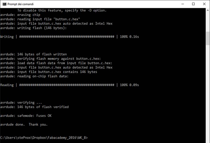
8th step: now that we have the C program and the Makefile ready, we will compile and upload it with AVRDUDE. So now opening the windows commands line and mouve to the directory with the .c file and the Makefile, after use the command below in order to burn the fuse bit, compile and upload our program.
If all it's okay, our board will have the green led blinking!
> make program-usbtiny-fuses
Tip: at the first attemp AVRDUDE (under Windows 10) doesn't work, I have fixed the problem following the instruction at the following link
Programming the Attiny44A with Arduino IDE
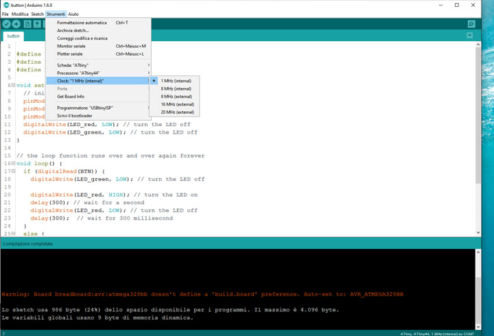
In the second part of this assignment I have programmed the Hello board with the same behaviors but with the Arduino evirorment. In order to do this I have followed this tutorial. So I have pasted this link in the "Additional Boards Manager URLs" that you can find under the preferences menu. After that from the boards manager we can install the Attiny core. Now we are ready to upload our program in the Attiny44A through the Arduino IDE.
- from Tools> Boards select Attiny
- from Tools> Processors select the Attiny you are using (Attiny44A)
- from Tools> Clock select the desidered one (1Mhz)
- from Tools> Programmer select the one that you are going to use (USBtinyISP)
- than upload the sketch
- Done!
void setup() {
pinMode(LED_red, OUTPUT); //initialize digital pin 2 as an output.
pinMode(LED_green, OUTPUT); //initialize digital pin 3 as an output.
pinMode(BTN, INPUT); //initialize digital pin 8 as an input.
digitalWrite(LED_red, LOW);//turn the LED off
digitalWrite(LED_green, LOW); //turn the LED off
The void setup will be execute only one time; here we Initialize the pins as OUTPUT or INPUT and turn off the leds.
void loop() {
if (digitalRead(BTN)) {
digitalWrite(LED_green, LOW); // turn the LED off
digitalWrite(LED_red, HIGH); // turn the LED on
delay(300);// wait for 300 millisecond
digitalWrite(LED_red, LOW); // turn the LED off
delay(300); // wait for 300 millisecond
The void loop will be execute forevere until reset or power off the board; with the if statement I setup the behavior of the leds when the button will pushed.
else {
digitalWrite(LED_red, LOW); // turn the LED off
digitalWrite(LED_green, HIGH); // turn the LED on
delay(300);// wait for 300 millisecond
digitalWrite(LED_green, LOW); // turn the LED off
delay(300); // wait for 300 millisecond
the else statement set up the behavior of the two leds when the button will unpushed; so the the green LED will blink with a delay of 300 millisecond.
Programming the board using the Arduino IDE and Attiny core.
Comparison
If we compare the two methods, the second one using the Arduino enviroment makes programming the Hello board very easy, because the Arduino method it's closer to our way of thinking conversely to use C and the registers. But with the Arduino way I will use 986 bytes of flash memory instead of 146 bytes, so is almost 7 times more resource consumption. Furthermore the memory data consumtion is 9 bytes with Arduino, but I haven't variables in the code. Using C and the registers I use 0 bit of memory data.
Analyze the datasheet: I started from consult the datasheet and check the important parameters to decide the model of the microcontroller to use.