Week 6
electronics design
I have never designed a electronic circuit before, this is my first time. the first step was to download the correct software to design the electronic circuits. with the help of my remote guru I downloaded Eagle.
This process was very simple to execute. I loaded the software using the terminal in UBuntu.
Loading the Software (Eagle)
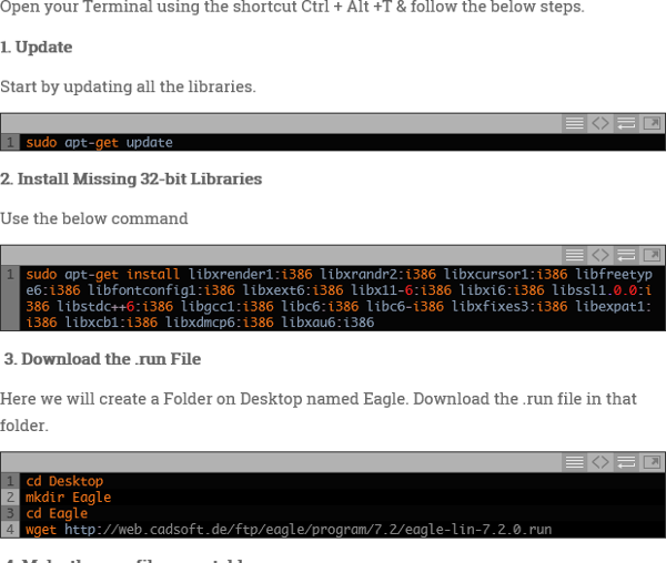
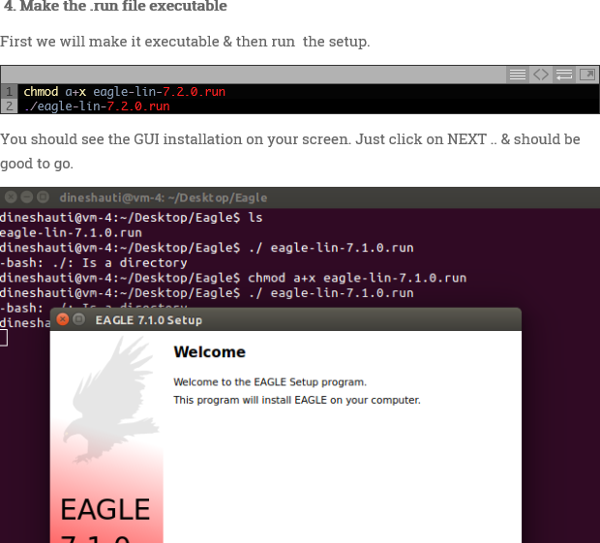
Just following the simple instructions to load Eagle and get it running.
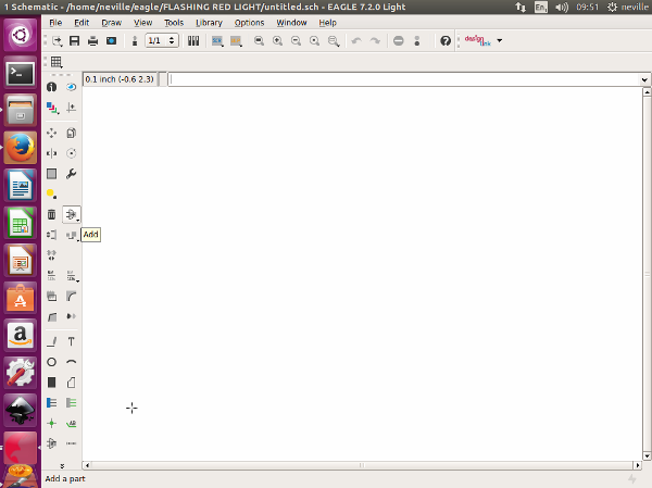
Opening a new file using Eagle.this was very simple . create new project then selecting schematic and then start designing by adding in components
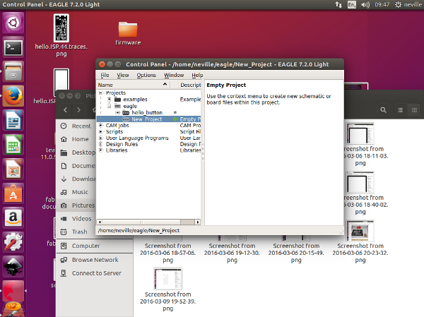
Opening the schematic view for designing and then clicking on the Icon to load components.
I then had to load the Fab Hello Button Liabrary and the Niel Gershenfeld Liabriary so that i would be able to get all my components available. I also Added the Fab Academy Liabrary as well.
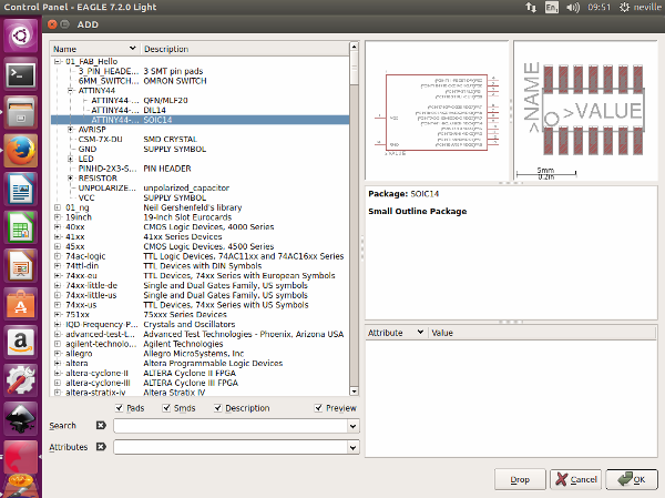
Bringing in the components . It was simplere to bring in all the components you need before starting to create you schematic layout.
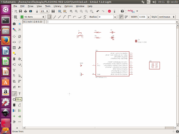
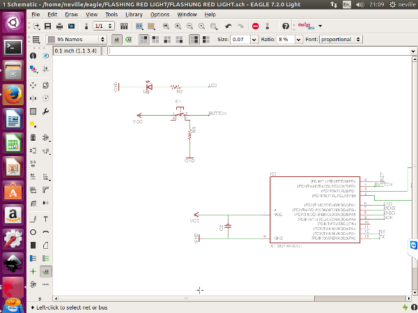
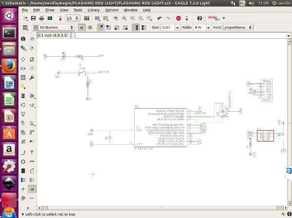
After bringing in all my components , i started to create my schematic design. I tried to link my components. It was then staring to seem like I was creating a complicated design and yet it was just a simple design. But this was because I was tring to link all the components with direct lines on the schematic and my lines started to cross each other or i needed to create a big loop for the line to join components so that they dont cross eaxh other.
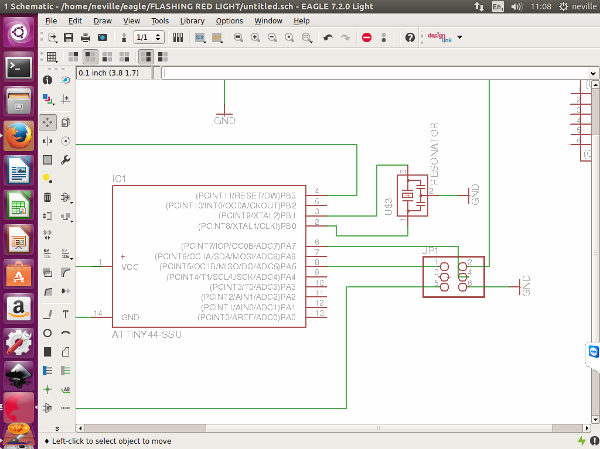
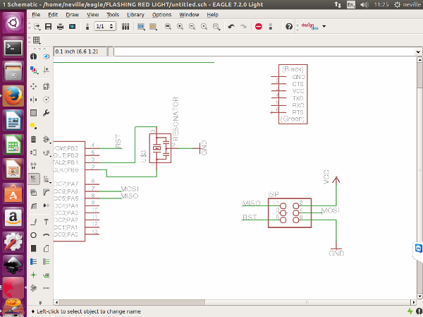
Then i learned that i did not have to physically show a link between parts but as long as I assign each line to link to a specific component as per the design it would automatically link on the board. This made things very simple going forward. I just made sure that i knew where each component connected and linked them and labeled them accordingly as well. Now my circuit did not look that busy and looked simple
Switching Views to the Board
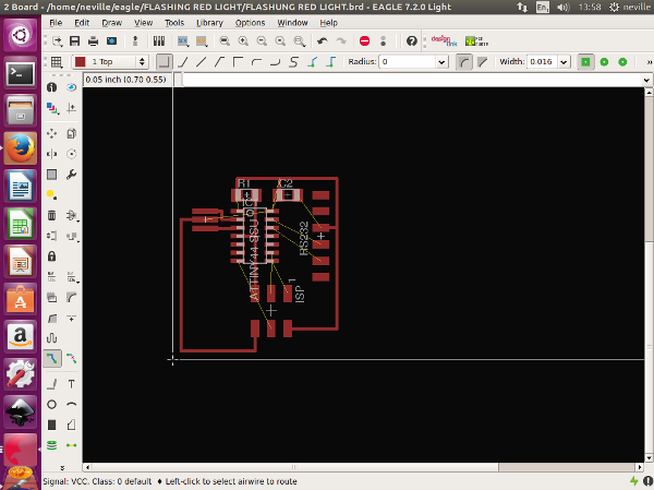
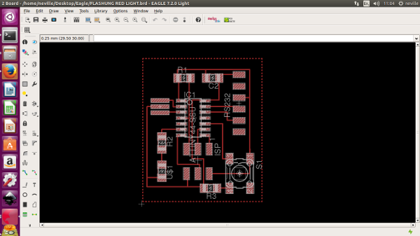
Now that i was finished with my schematic design, i switched to the board. This was a bit of a shock. made it look so much more complicated with so many lines all crossing each other. I brought in the components into the board area from outside the board area as you cannot work with the components outside the board area. I focused first on the board but did not want to bring in the switch and the LED just Now. i started to arrange the Board the way i wanted it to look like. because there are so many examples available, i was aware of what my board should look like.The software allows you to use an automatic feature. This uses the information avilable and shows you the best way the board should be done. this is just a guide and once it does that, it helps you to complete the design to what you want it to be.
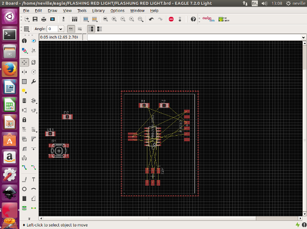
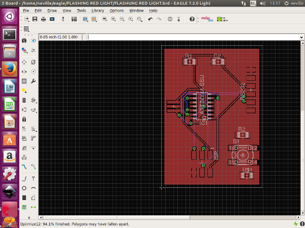
There is a feature that allows you to edit the automatically calculated board layout. i started to get my board looking right.
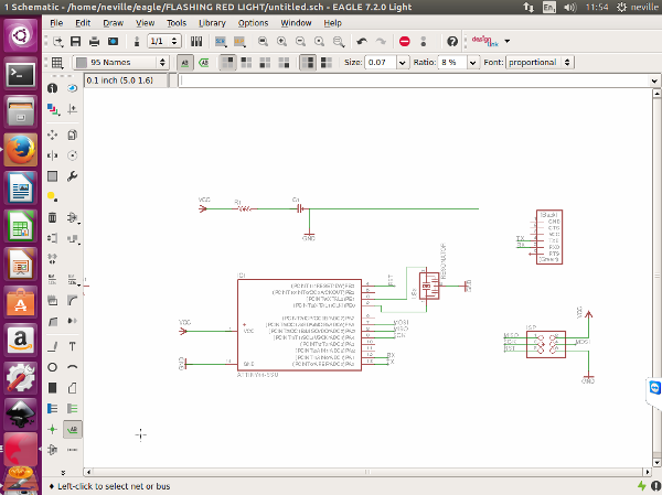
I had to get back to the schematic Design to add my switch and my LED
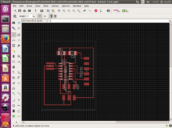
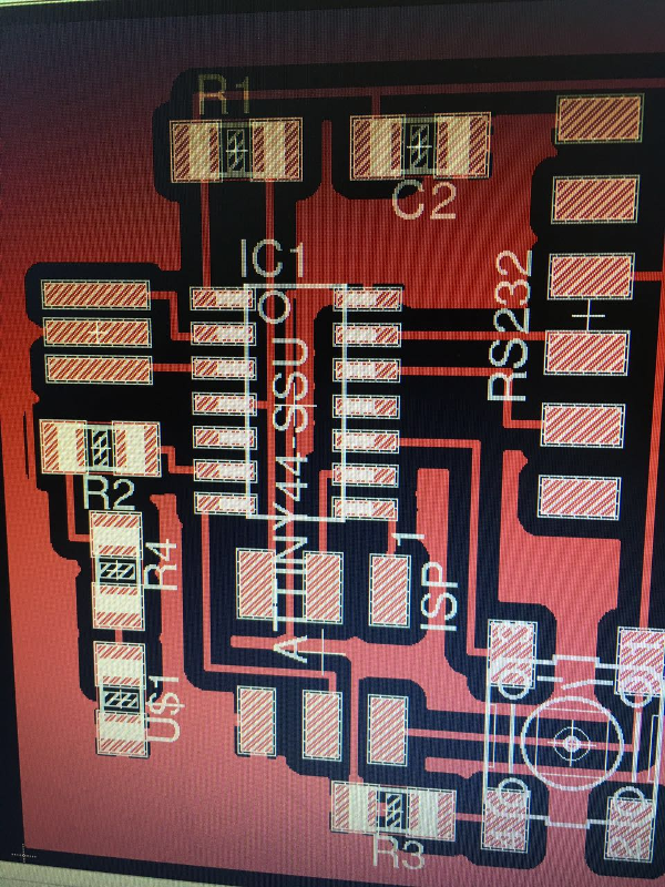
I follwed the same steps as before and created my final board design . Looking all good
Now that my design was completed it was time to actually cut out the design on my Board and get the components soldered on. making my Hello Button Light become a reality.
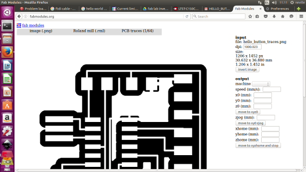
Now that my design was completed it was time to actually cut out the design on my Board and get the components soldered on. making my Hello Button Light become a reality. I needed to create a PNG file so that i can cut out my circuit board using the modela mdx20. i selected the export function an dcreated the PNG file.
After creating the PNG file i went into fabmodules to print my board. I went to output Format, Image and brough in the PNG File then the output Format, selcted the Roland mill. then the PCB traces (1/64) then again on the right hand side i selected my machine which is the MDX 20 the one thing also for the machine to move , i had to add ./ infront on the send command line as shown in the pictures. I then claculeted the traces and it provides a view of how the traces would be milled.then i went to get my machine(MDX20) ready
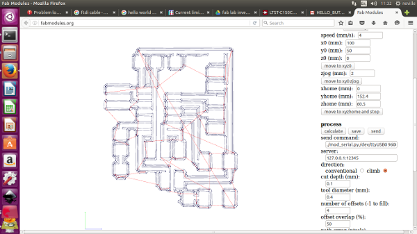
I used an existing board that was already stuck on the machine bed which still had space for me to make another board.so I had to offset my start point/orign. to make the machine talk to the computer i had to first go through the terminal to make sure that the terminal can send the instructions to the modela. I follwed the same steps i did for my ISP board.
i had to first open the terminal and make sure that it is connecting
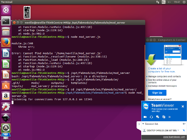
Now the Machine is all set to "talk" to the Modela. Selecting the mill that is needed to mill the board. The 1/64 Bit
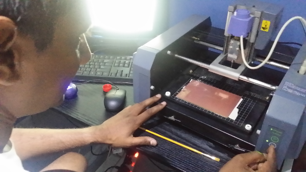
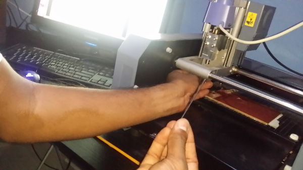
Setting up the Modela and making sure the XYZ is all set correctly before cutting

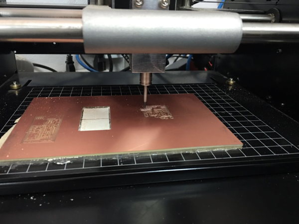
Ready To Mill. i go back to the fabmoule page and then select send , and there it goes , it starts to mill my first designed board.
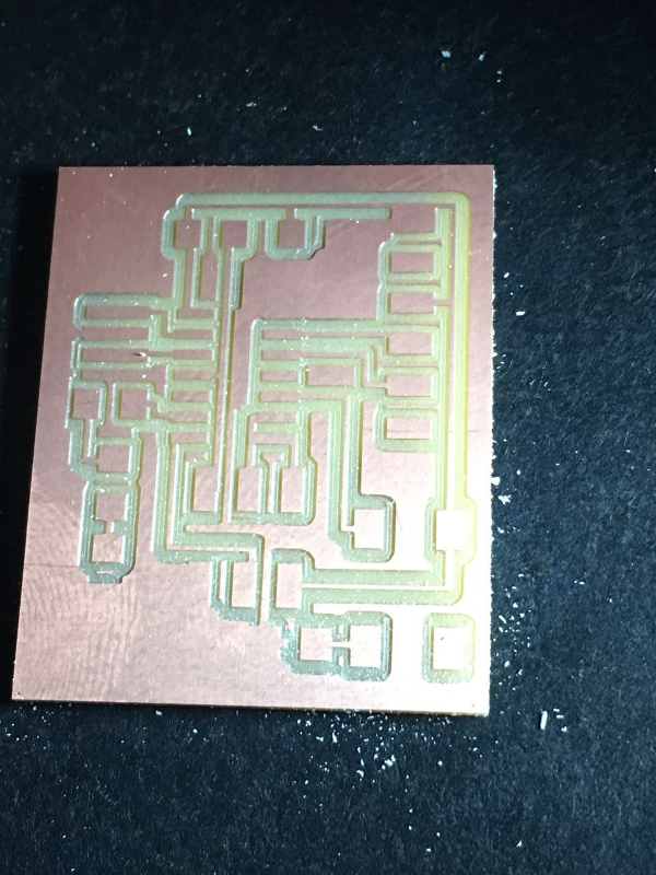
Ready to remove milled board
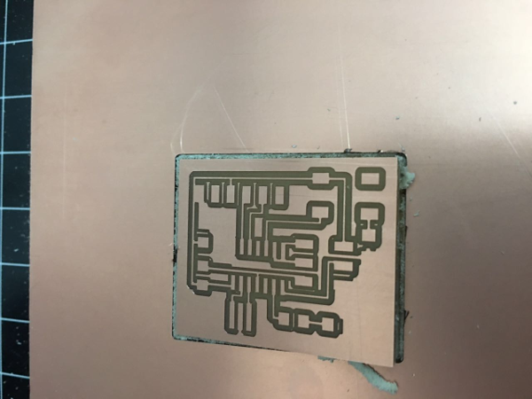
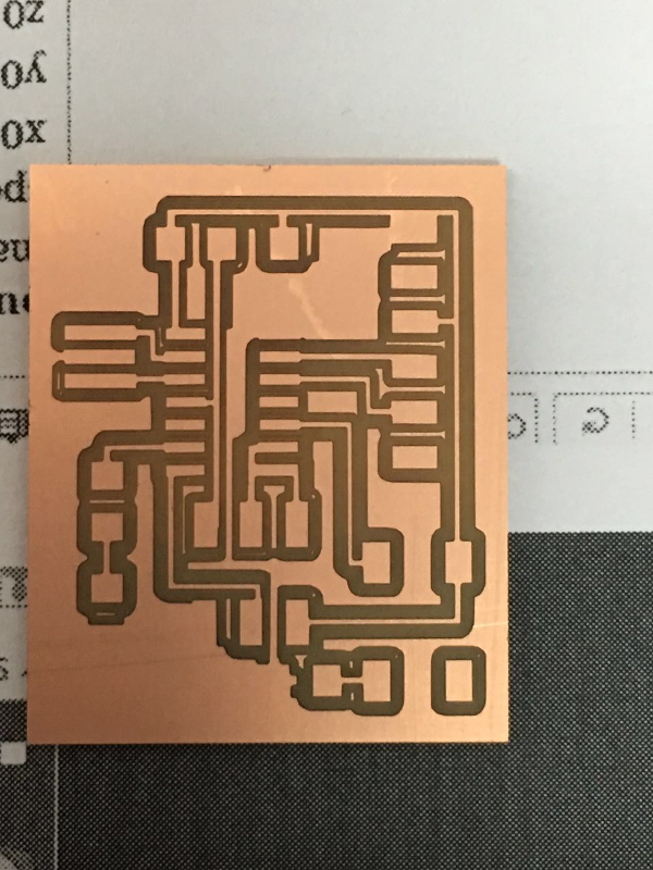
the final cut out Board, Perfect, well i hope so
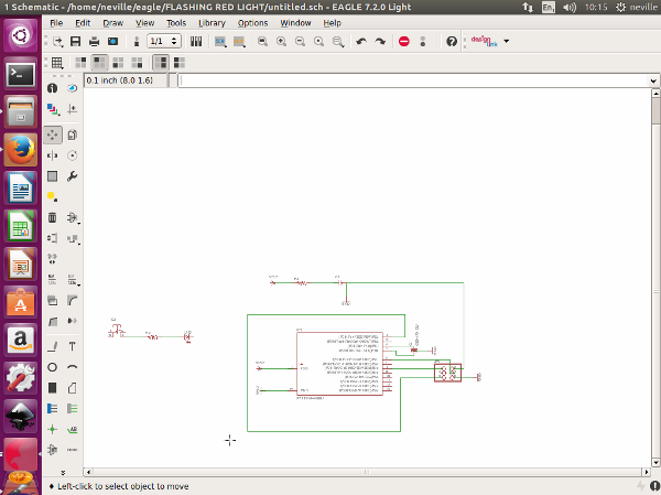
Now for the components to be soldered onto the board This is when i encountered lots of problems, I should have checked before i started if i have all the correct components . one of the components needed was a 200 ohm resistor. i did not have a 200 ohm resistor. but i did have 100 ohm resisters , which meant i could combine two 100 ohm resistors in series and create a 200 ohm resistance. But my Board was already milled only allowing for one 200 ohm resistor. I had to go back, to eagle and redesign. It was quick as i folled the same steps just added another resistor.this did not take me much time as i had learnt the software very quickly , i quickly edited the schematic and the board and was ready to cut the board.
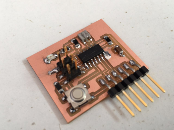
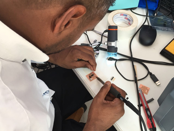
I then started to solder the components onto my board
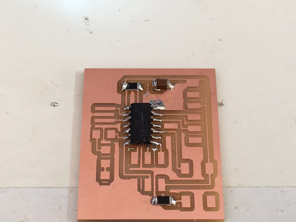
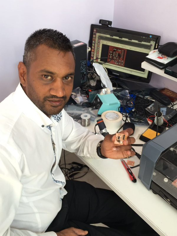
My final Hello Botton Light Circuit Board all done and ready for programming