Week 4::Electronics Production
Learning outcomes: Describe the process of production and programming. Demonstrate correct work flows and identify areas for improvement if required. Source Files.
Describe the process of production and programming:
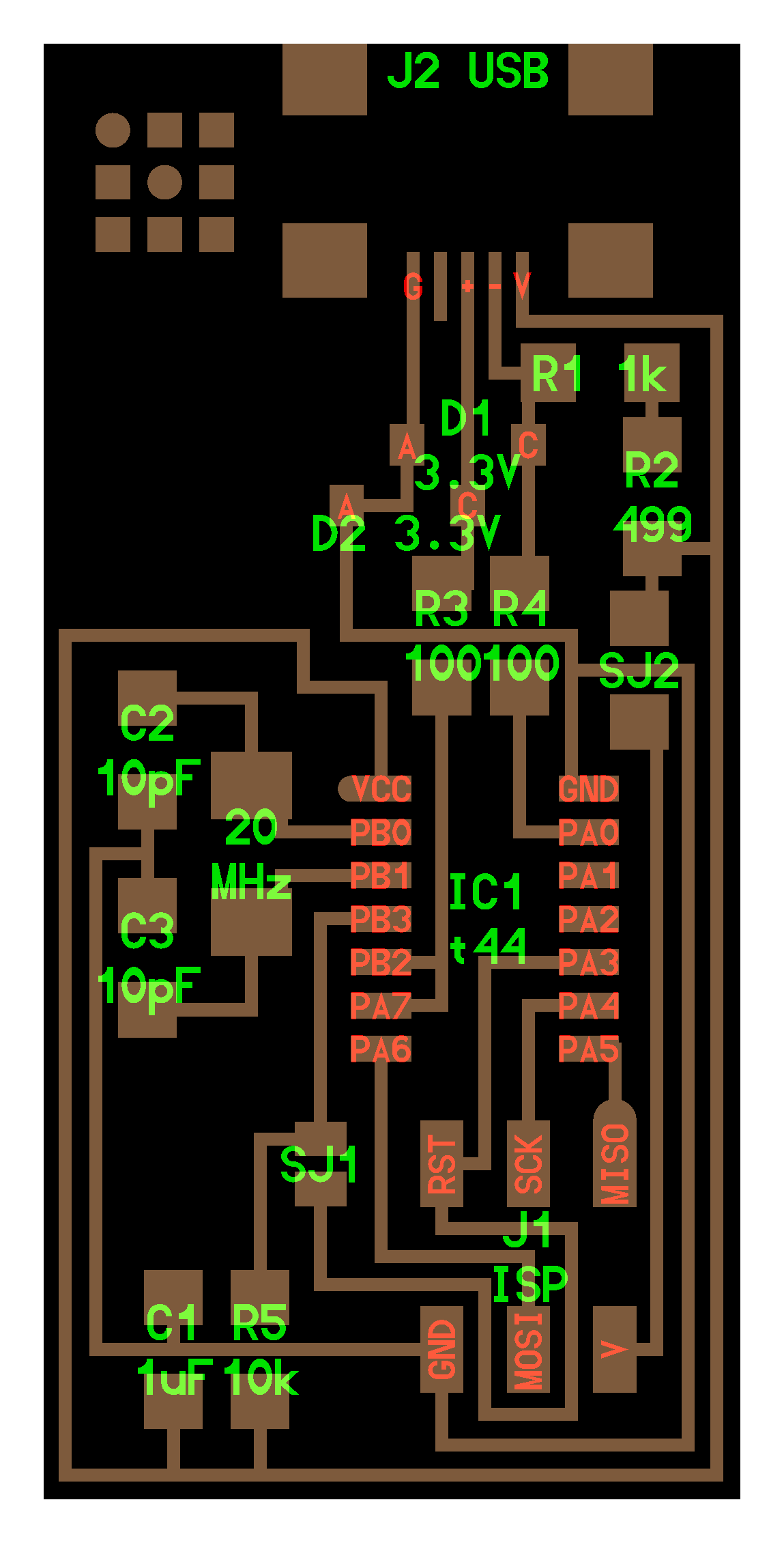
This I make a FabISP, which is an in-system programmer. For this task the layout were already provided.
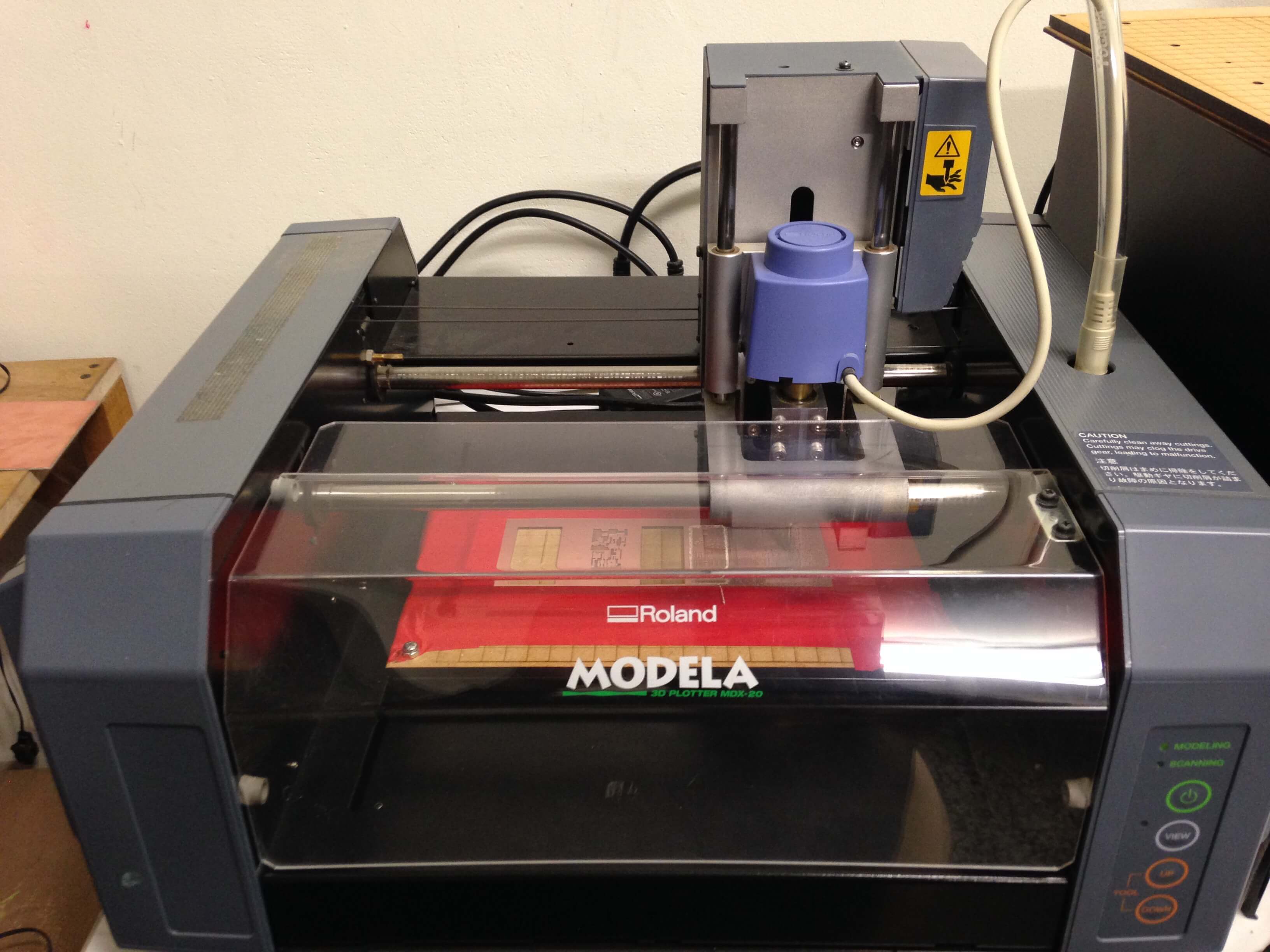
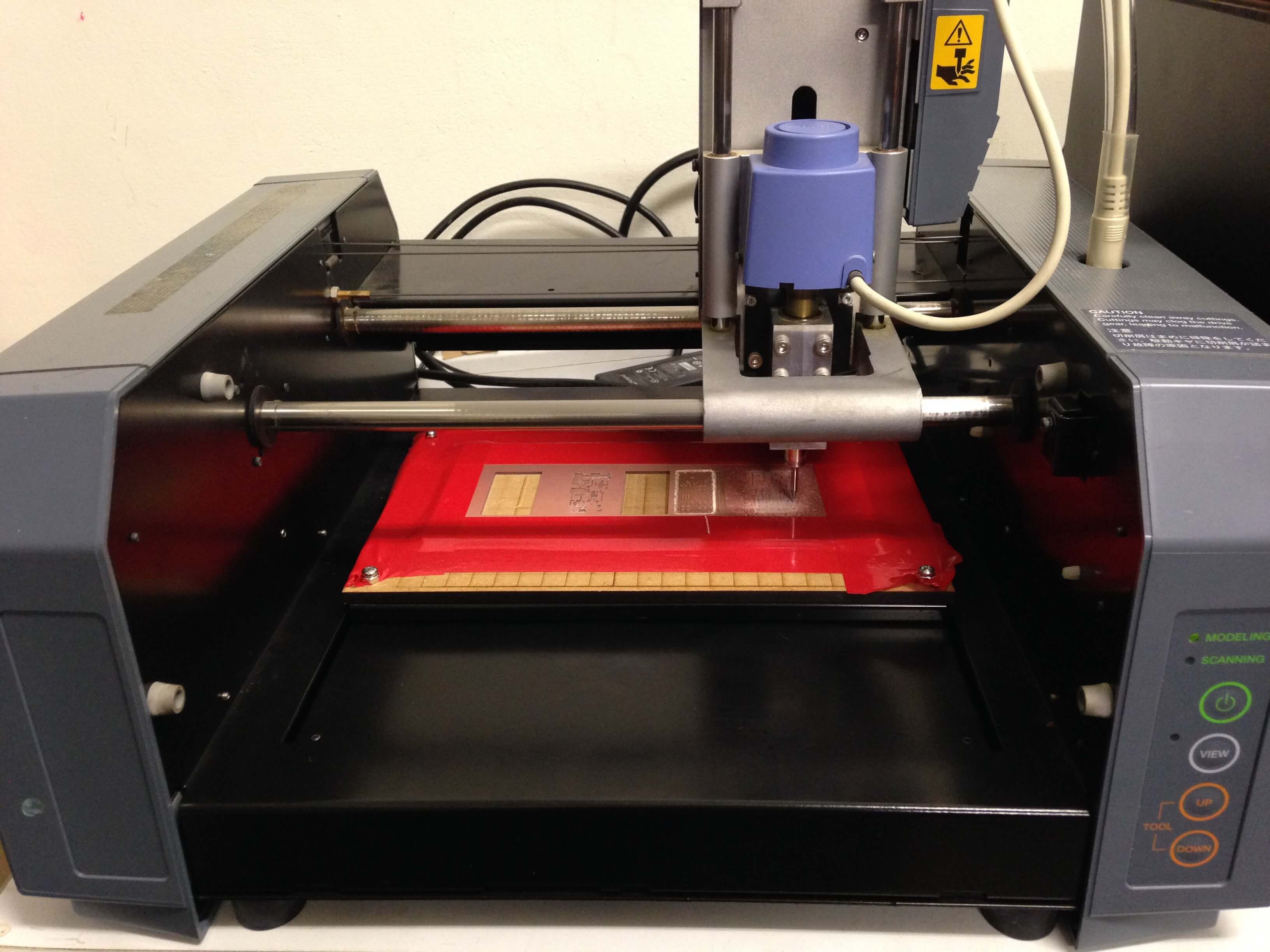
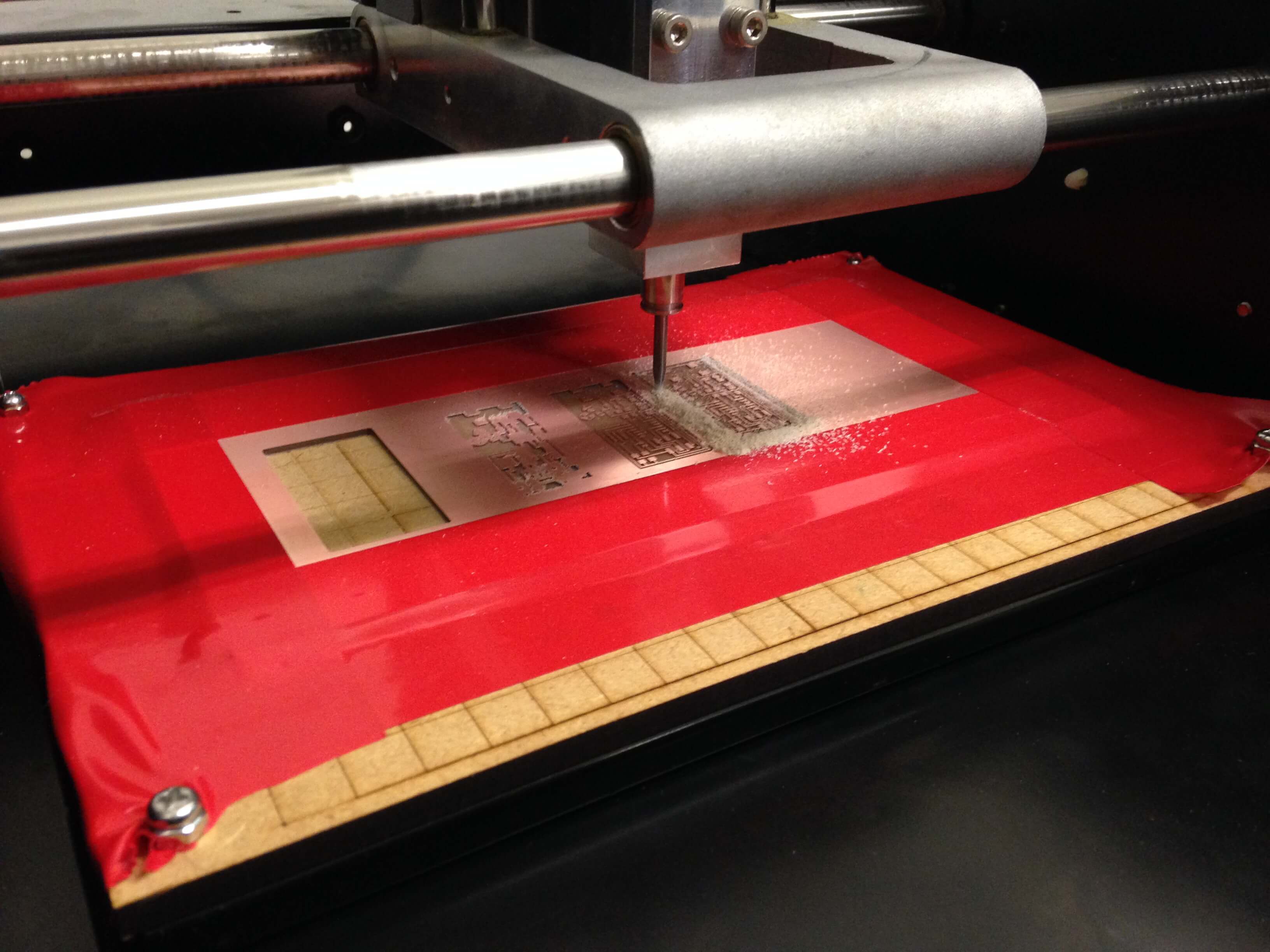
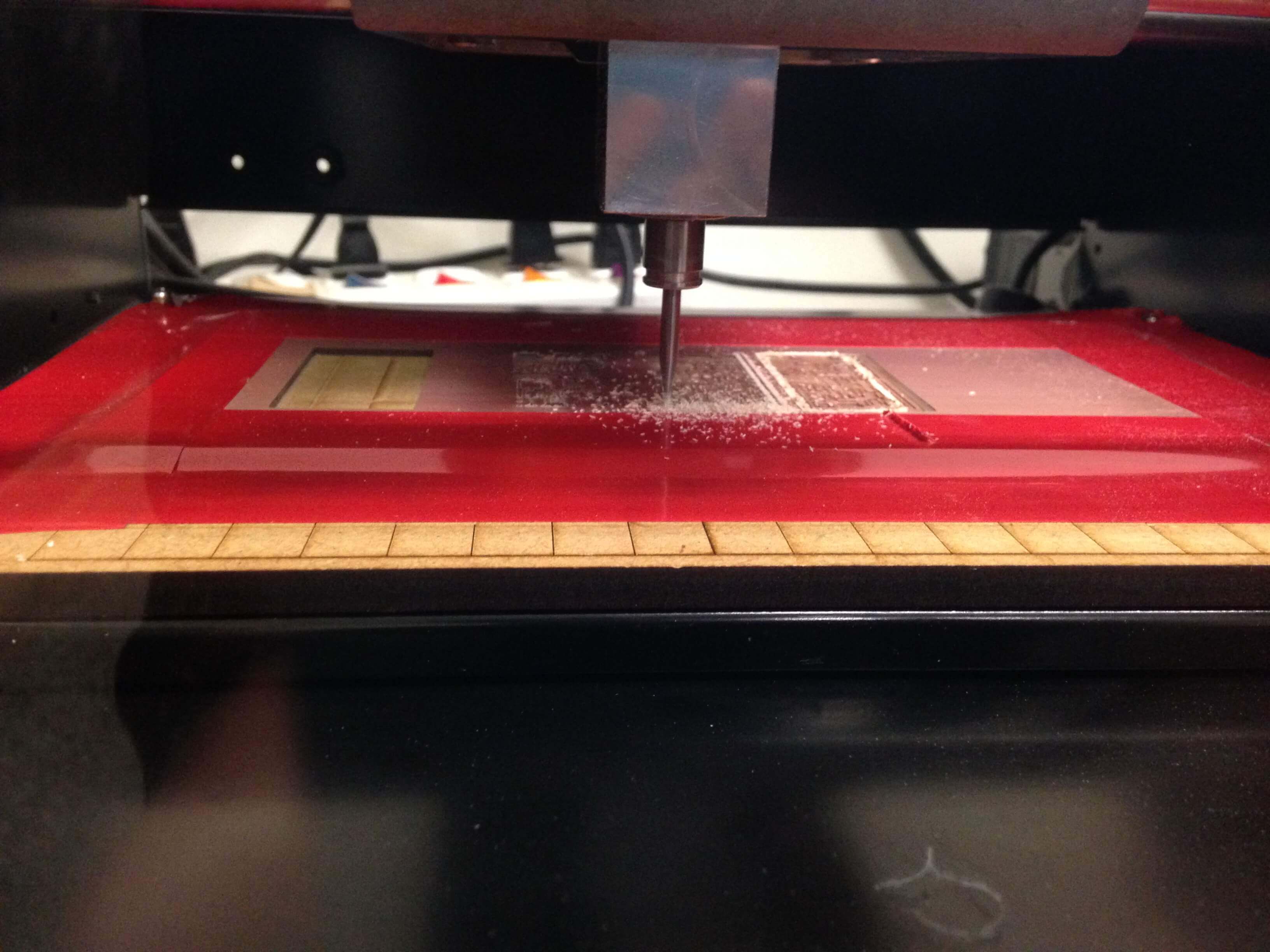
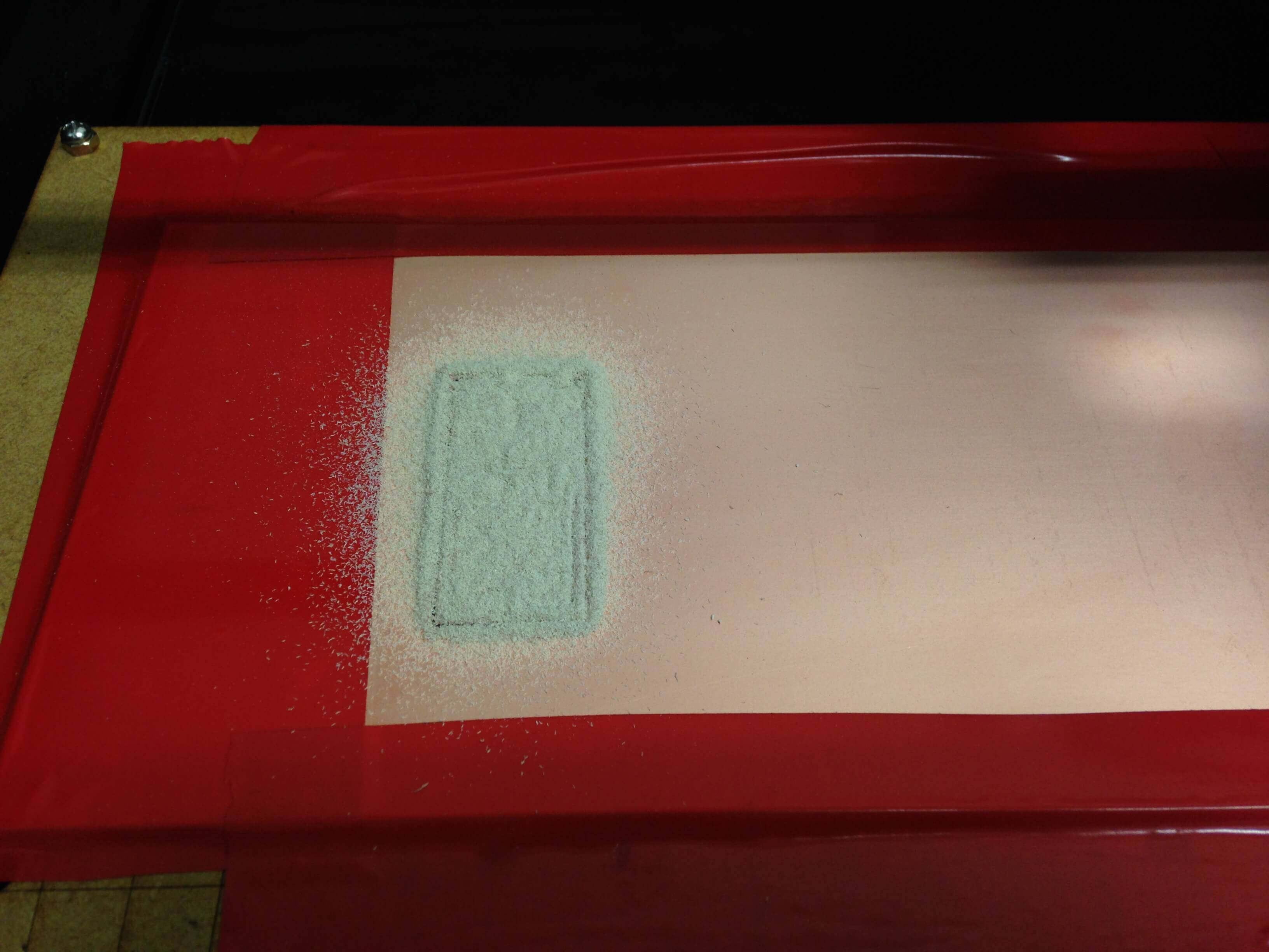
Milling the board.
For milling the board I was used Roland Modela MDX-20. There were two milling bit sizes required, 1/64 for the traces and 1/32 for cutting the board out.
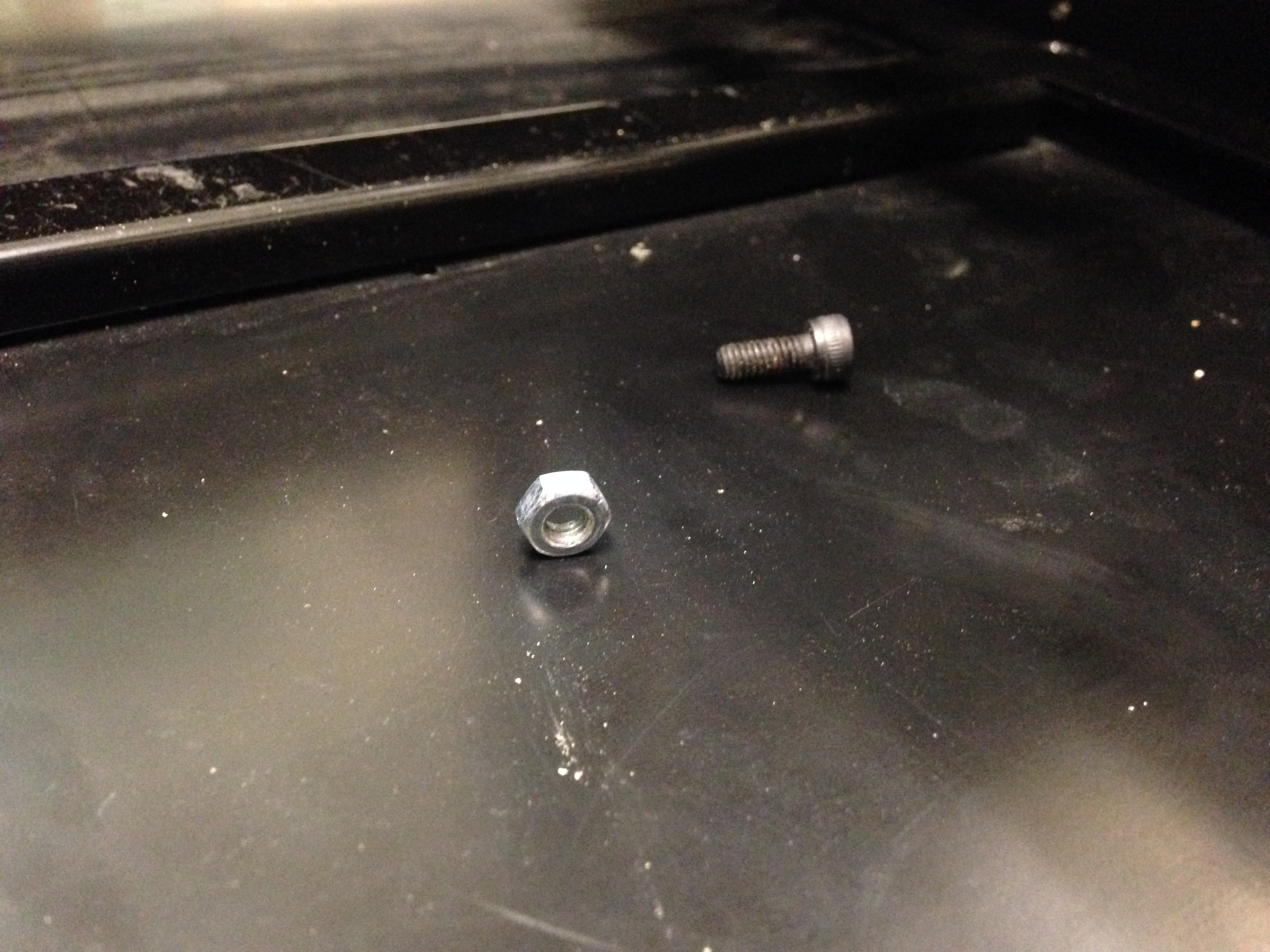
At the beginning two screws were release so we can not to use it to mill board. Then we solve these problems.
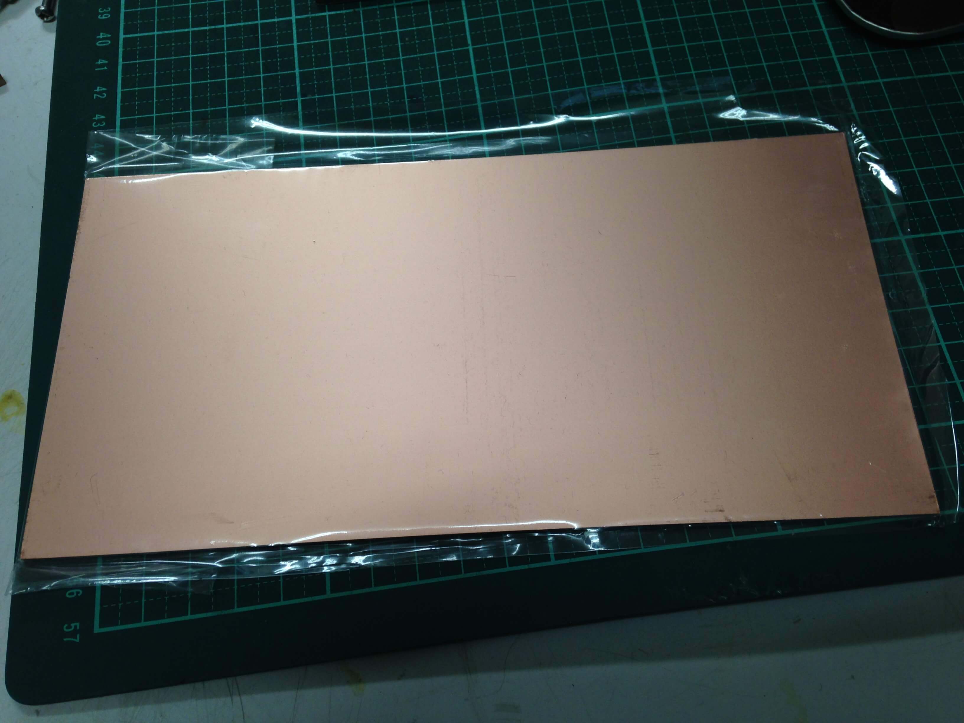
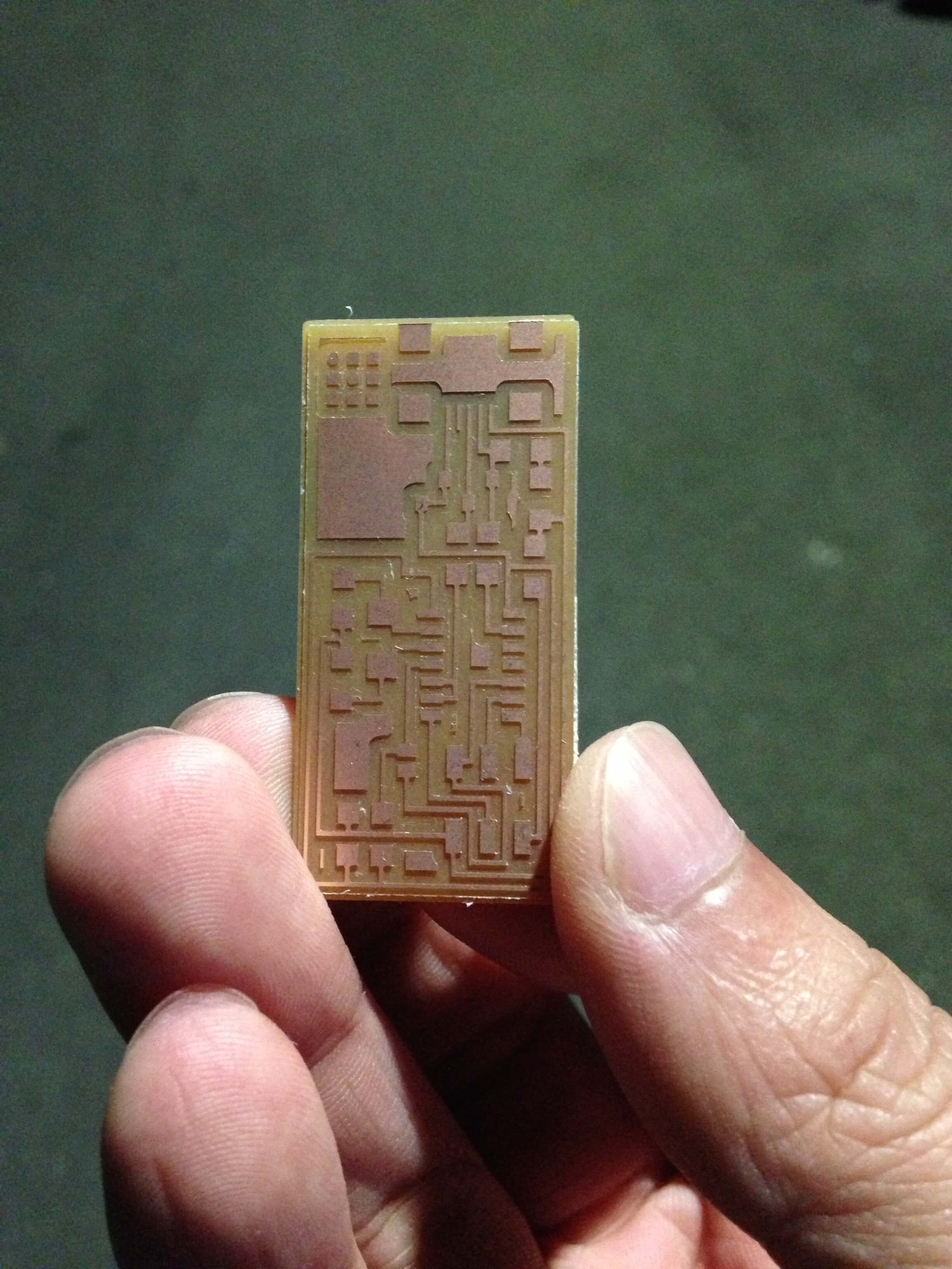
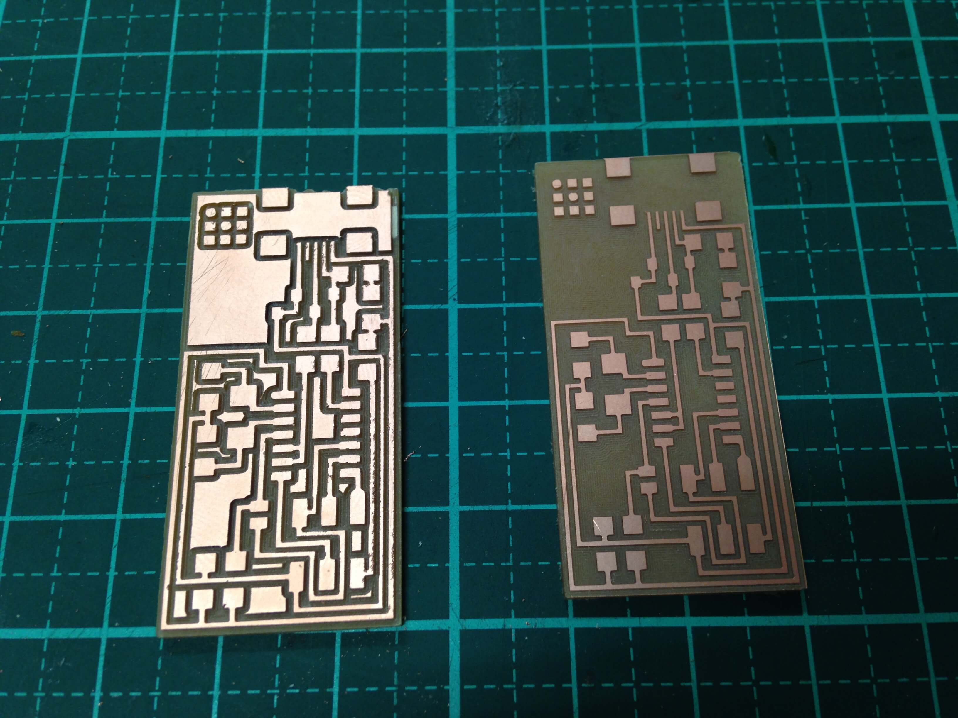
First I needed to download the layout (traces) and the interior (for cutting the board that you can get it out of the bigger cupper clad.)
After that I fired up the terminal in Ubunto and started the fab module with the fab command. Then there would dialogue boxes that are very intuitive. In the first dialog box it should be selected from what format to which format. For making the PCB with modela they are:
From format: image (.png)
To format: Roland modela (.rml)
And after that the “make_png_rml” button should be pressed
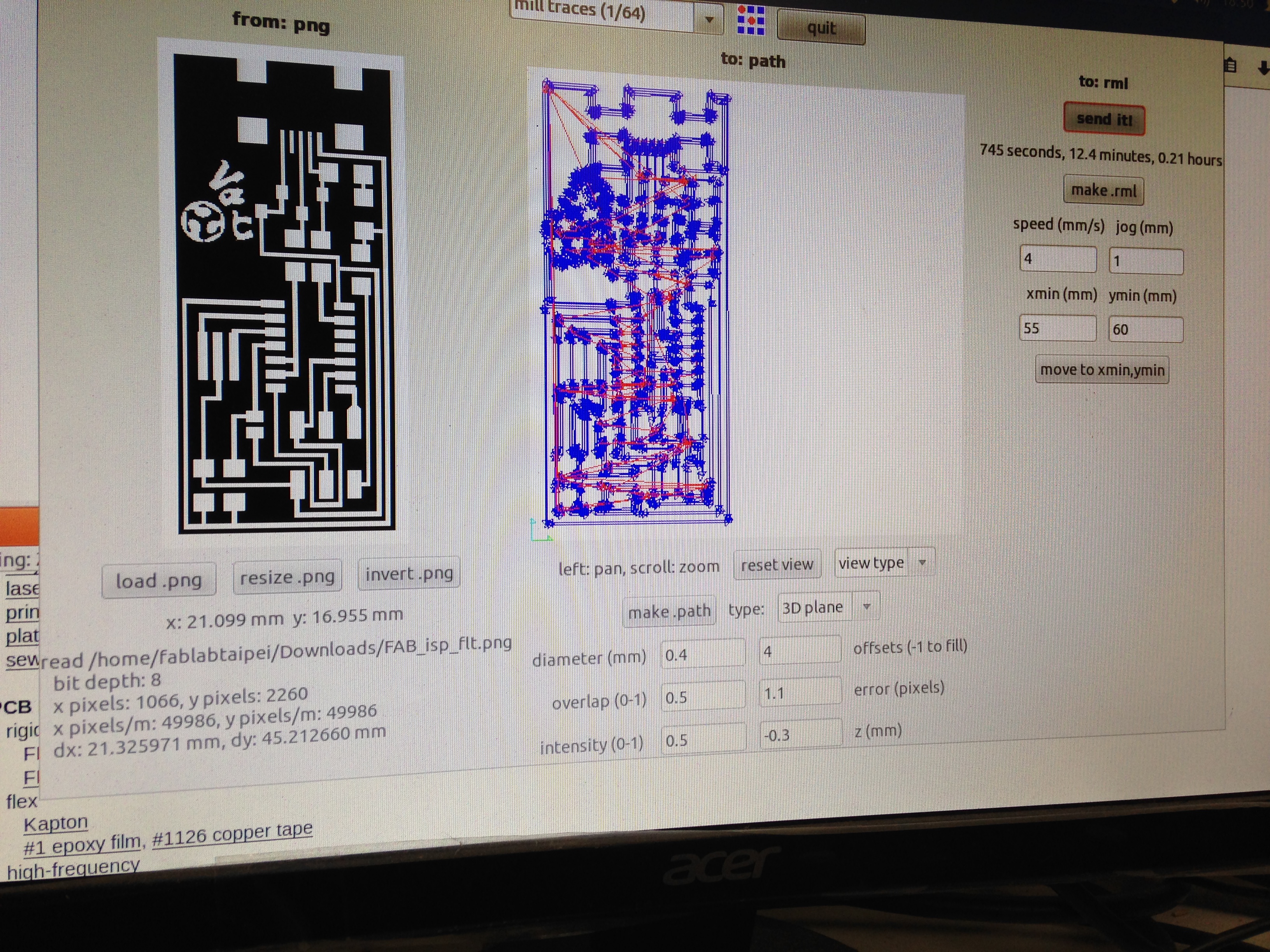
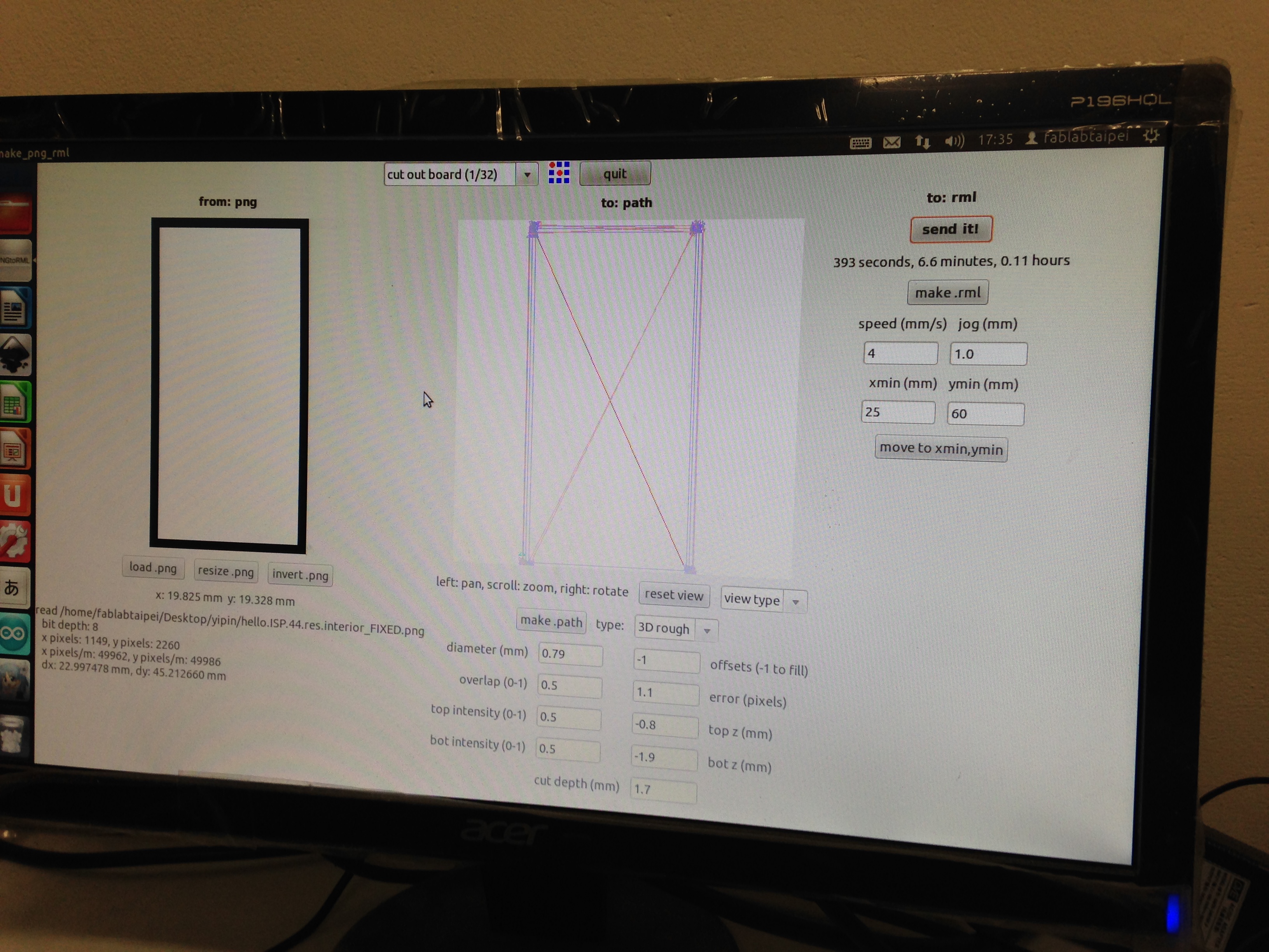
For milling the traces board. The variable what is set:
Milling the traces:
diameter(mm):0.4; Offsets:2
Overlap:0.5; error(pixels):1.1
intensity:0.5; z(mm):-0.15
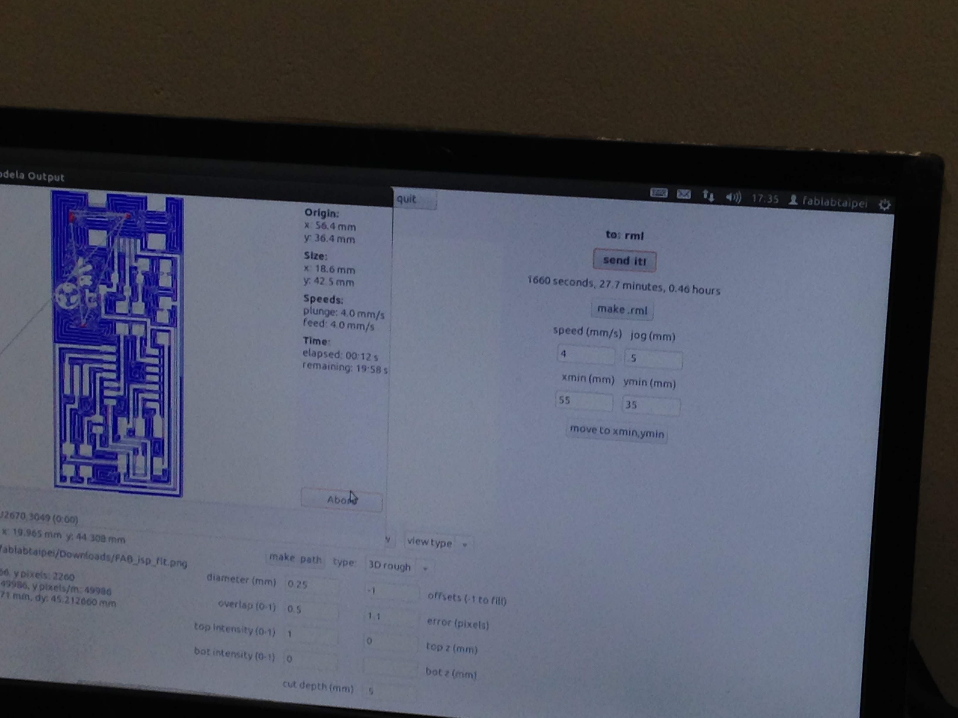
Milling the border:
diameter(mm):0.79; Offsets:2
Overlap:0.5; error(pixels):1.1
top intensity:0.5; top z(mm):-0.8
bot intensity:0.5; bot z(mm):-1.9
cut depth(mm):1.7
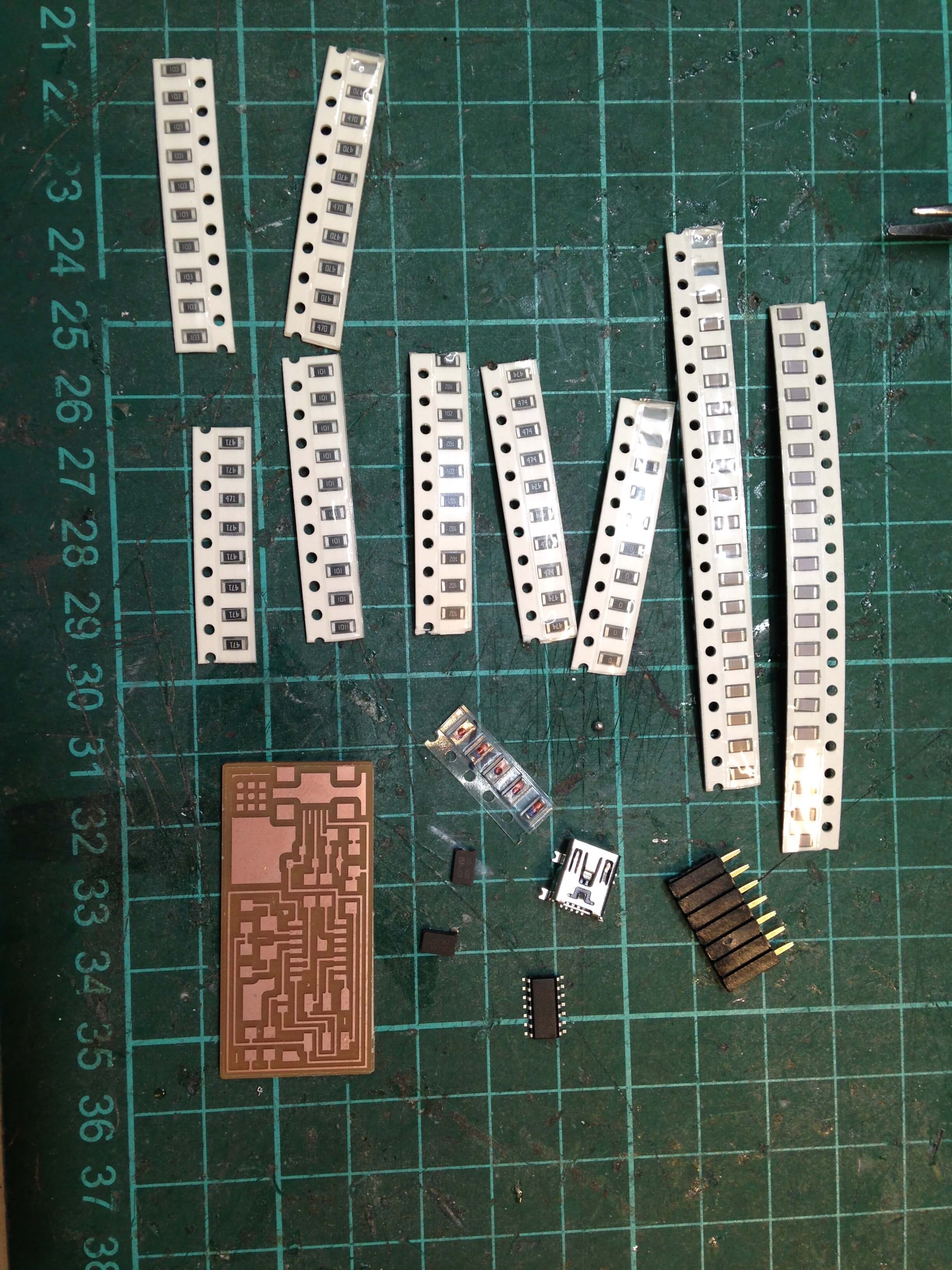
After milling the board, start to soldering the board.
Solder electronic components:
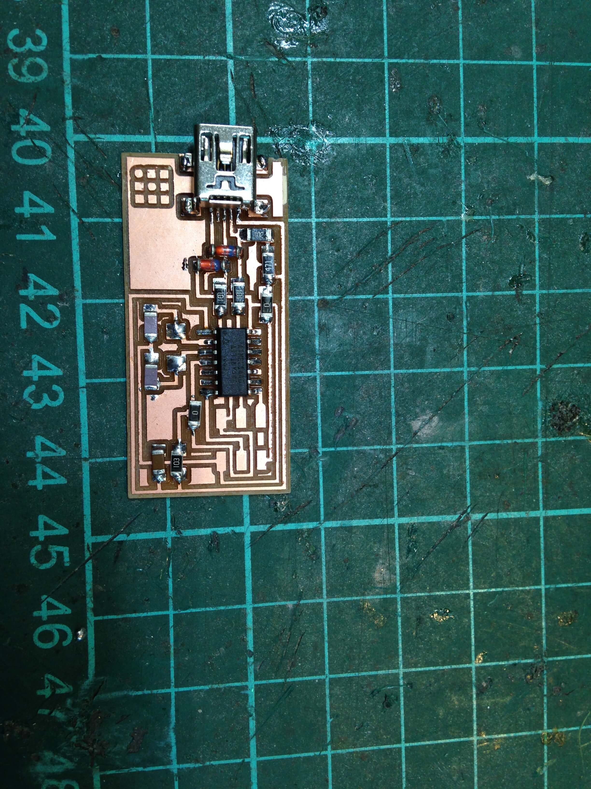
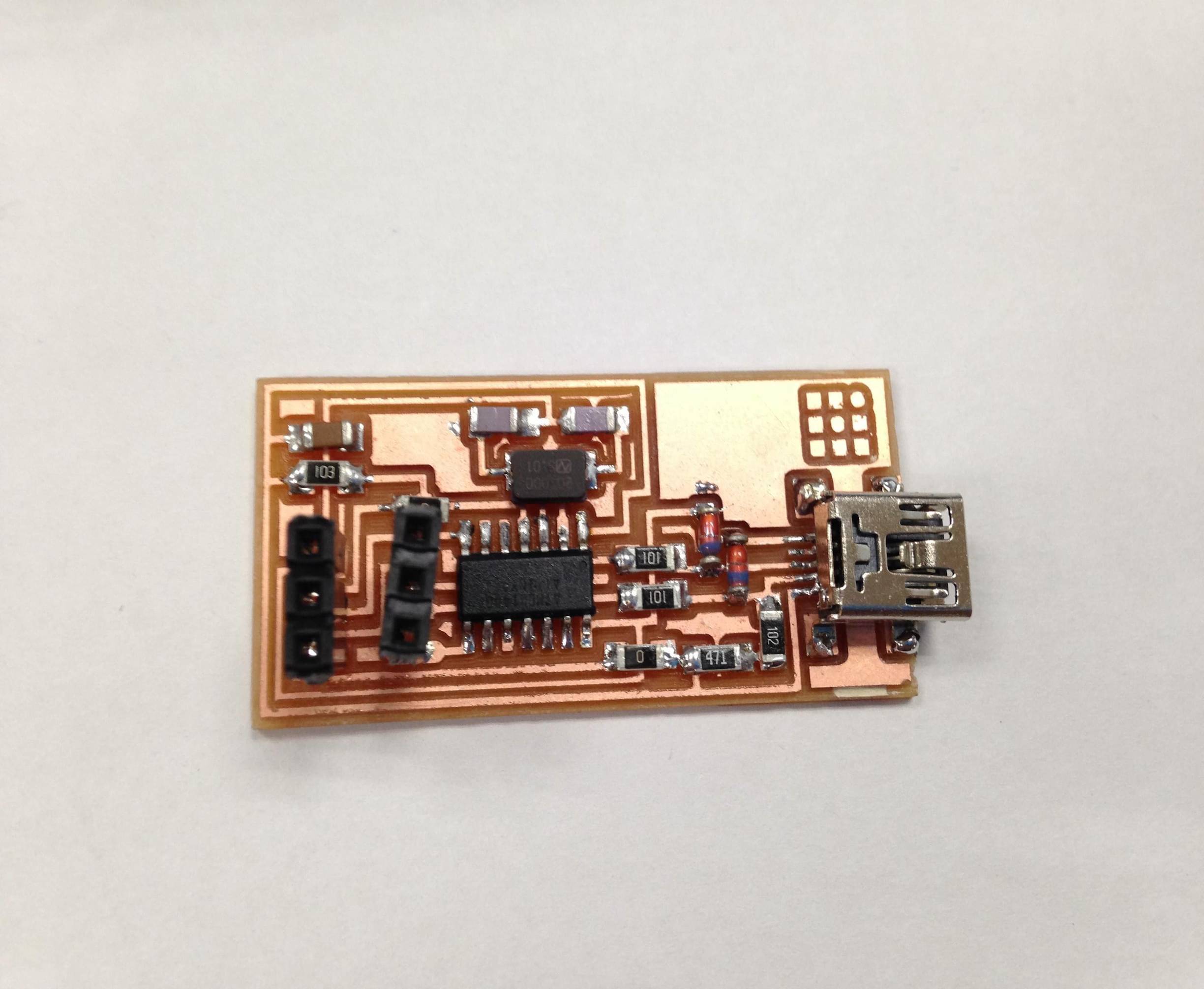
After soldering the board, FabISP.
Demonstrate correct work flows and identify areas for improvement if required:
Following the tutorial from FabAcademy How to Assemble and Program the FabISP. to program the FabISP.
Following the tutorials, I have finished to program my FabISP.
Download the firmware from FabAcademy website.
Then open my terminal to unzip the firmware.zip and move into the directory on my notebook.
cd ~/Desktop
unzip firmware.zip
cd ~/Desktop/firmware
I was used AVRISP mkII for power the FapISP board and programmer.
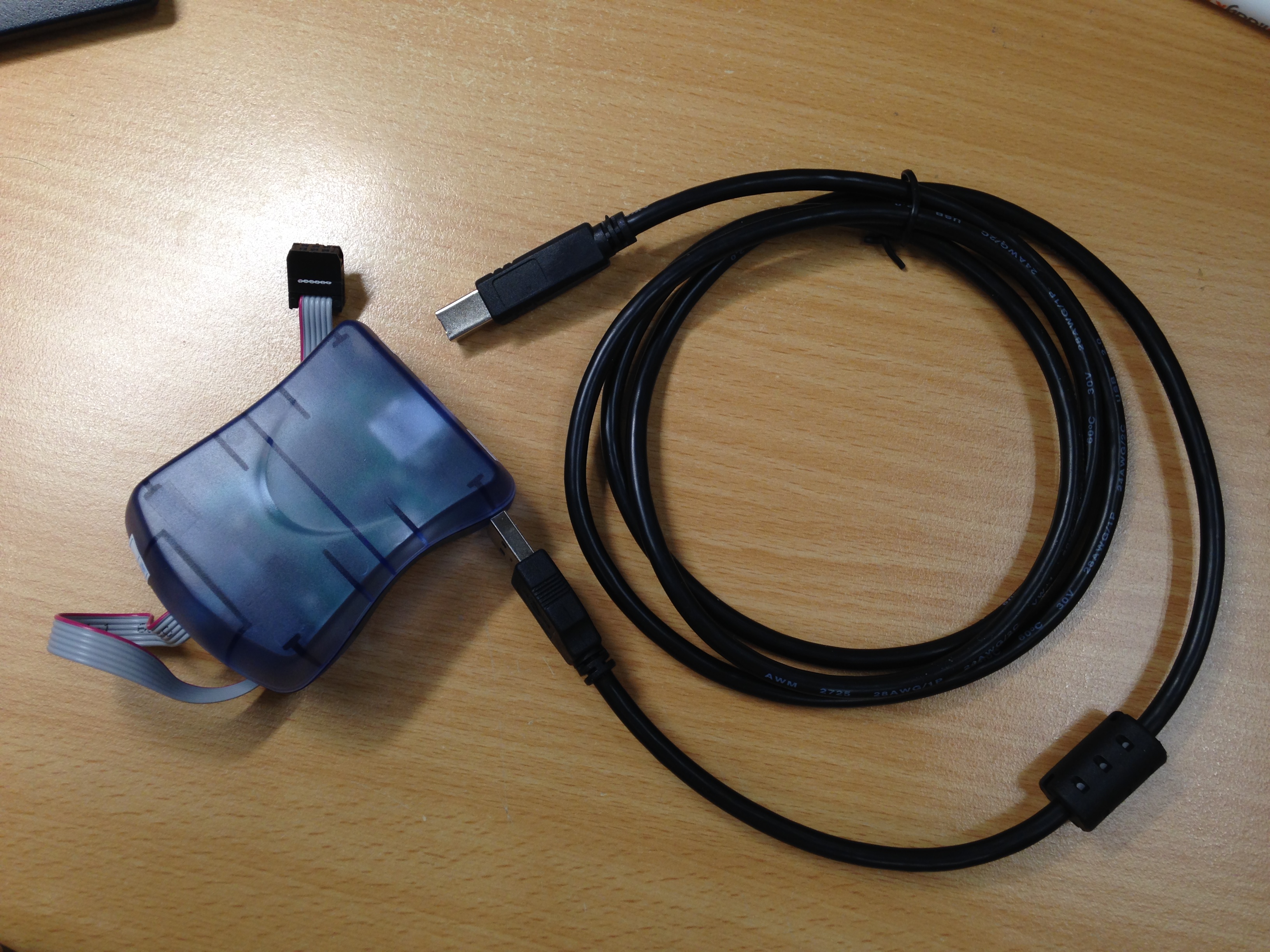
Because I was used AVRISP mkII for power the FapISP board and programmer. So I do not need to edit the makefile.
Then open my terminal to type the command to program the FabISP.
make clean
Then I am successful. See this response from the system.
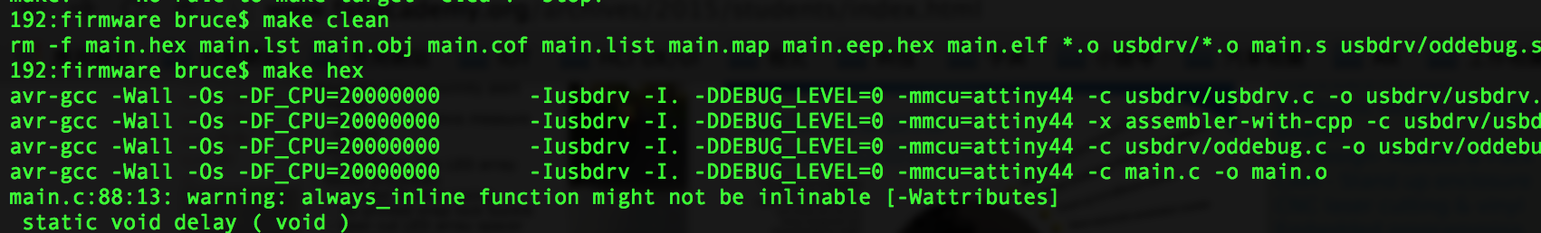
Type:
make hex
Then I am successful. See this response from the system.
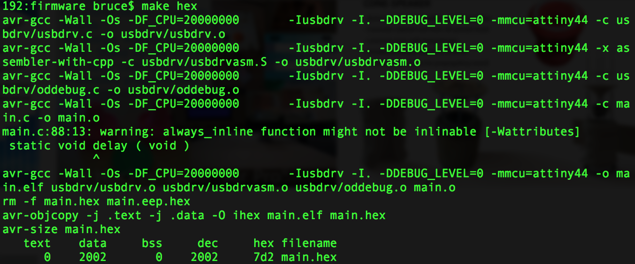
Type:
make fuse
Then I am successful. See this response from the system.
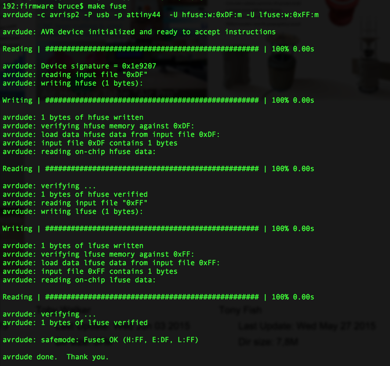
Type:
make program
Then I am successful. See this response from the system.
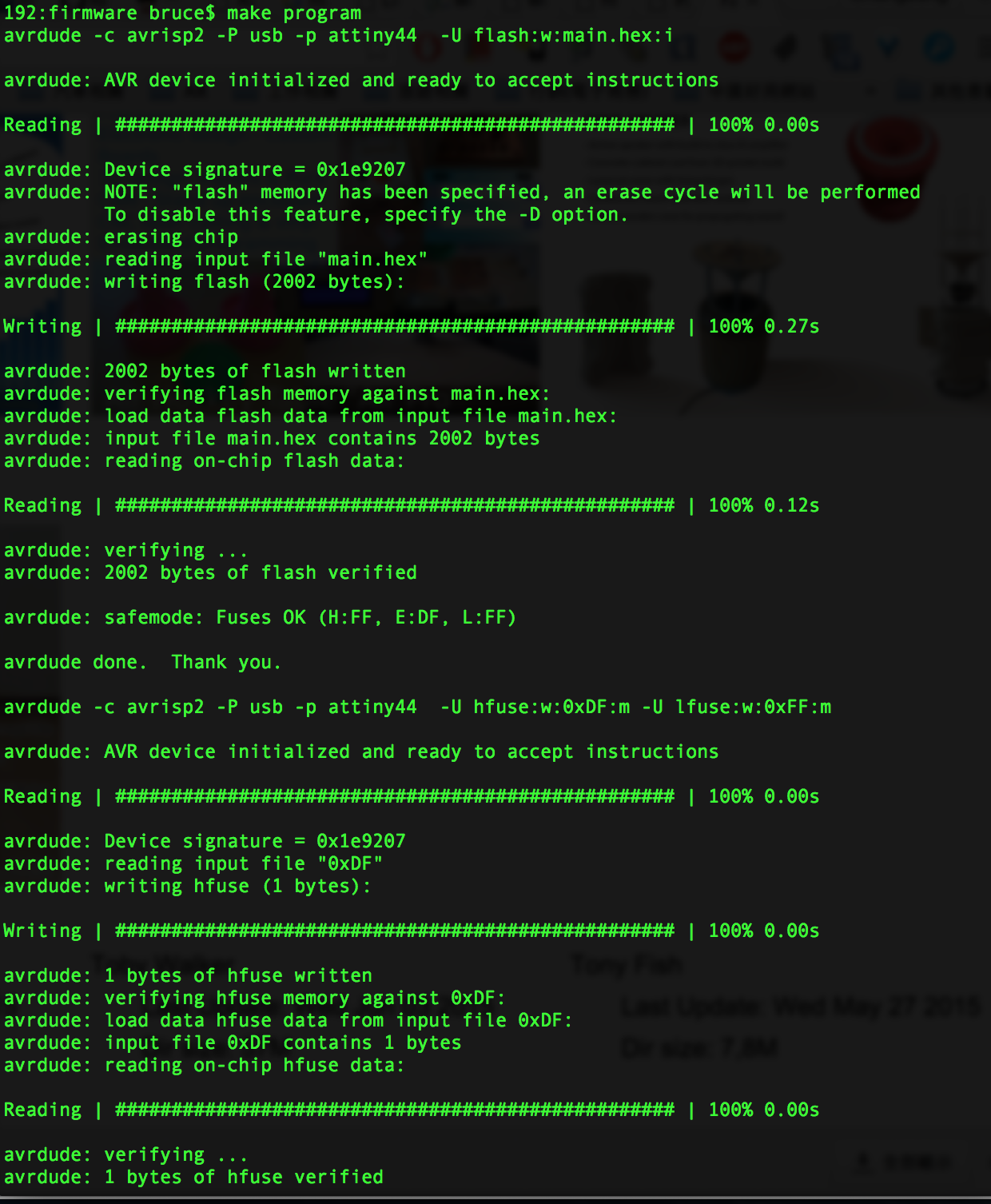
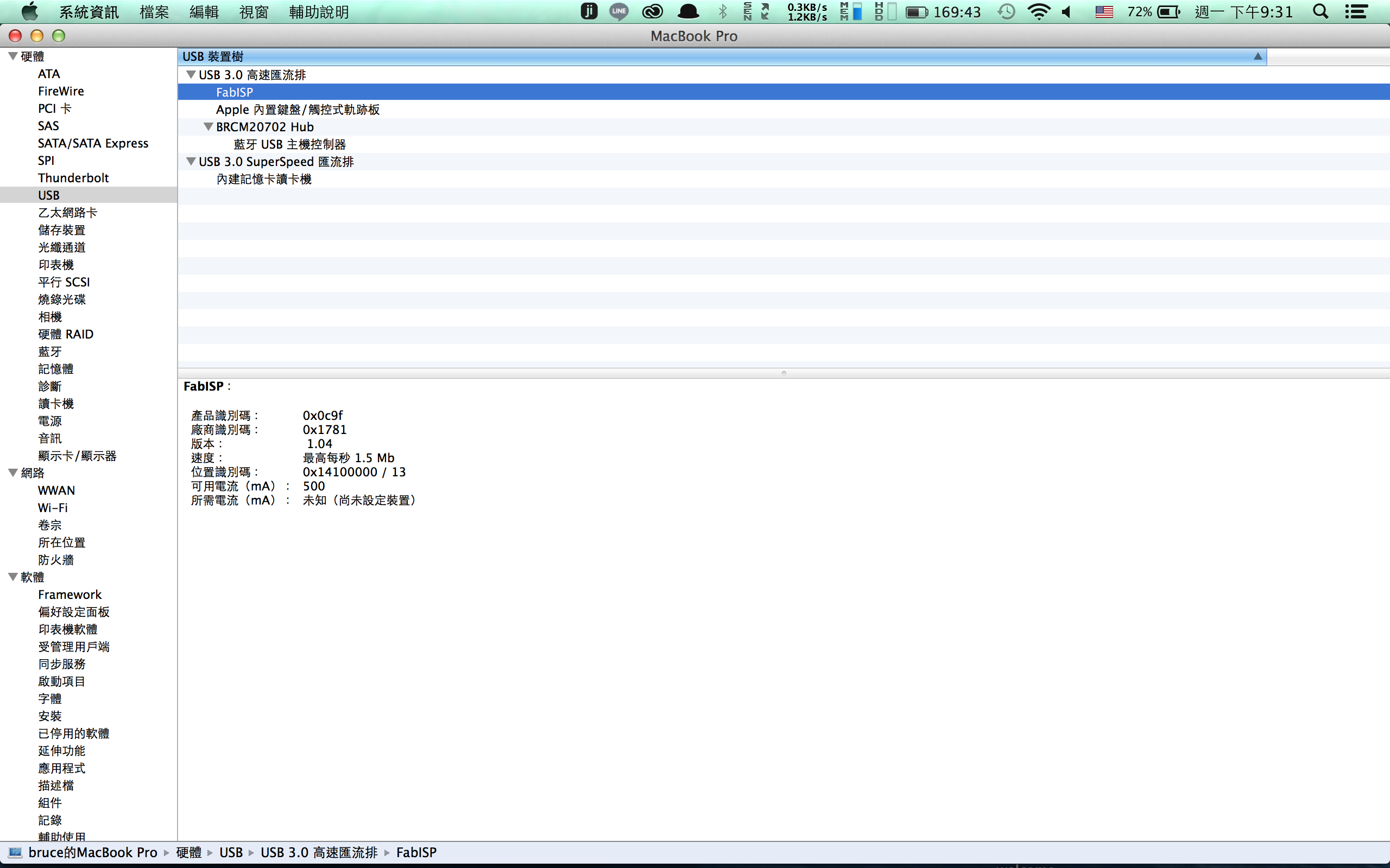
After program my FabISP, to verify that my FabISP is working correctly.
Go to the System Profiler -> Hardware -> USB -> Hub.
My FabISP device has been successfully programmed and is recognized by my computer.