Week 15::Embedded Networking and Communications
Learning outcomes: Demonstrate work flows used in network design and construction. Implement and interpret networking protocols. Source Files.
Demonstrate work flows used in network design and construction:
In my final project, when the fishing float detect gravitational acceleration from ADXL345 then send a signal via RF433MHz to rod base.
So this week assignment I used RF433MHz module (wireless radio frequency) for my embedded networking and communication.
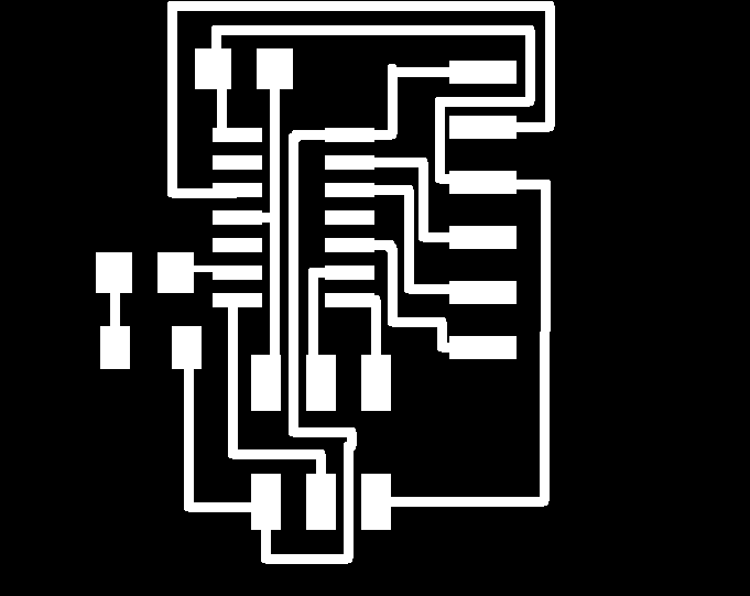
I used eagle to design board for receiver. But Attiny44 was not to support VirtualWire Library. I will keep trying to find out to solve this problem. But this time I was used satsha kit.
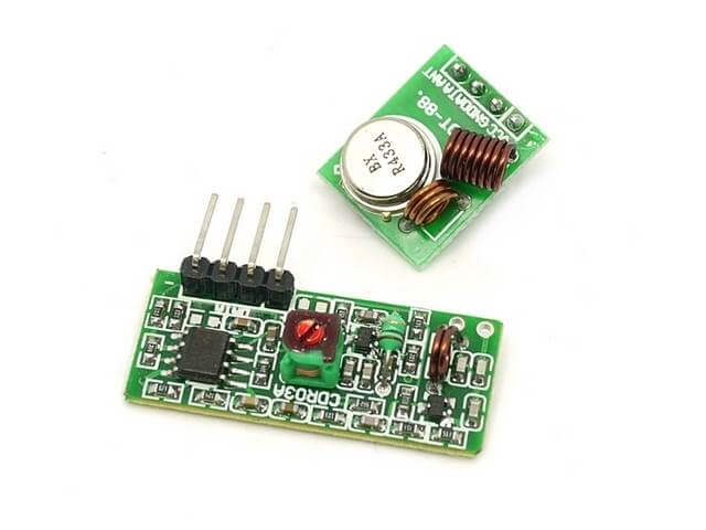
RF433MHz Modules are popularly used in remote control system. The maximum range of transmitting distance is around 100m in open areas.
I think the quality of transmission better than bluetooth .

Implement and interpret networking protocols:
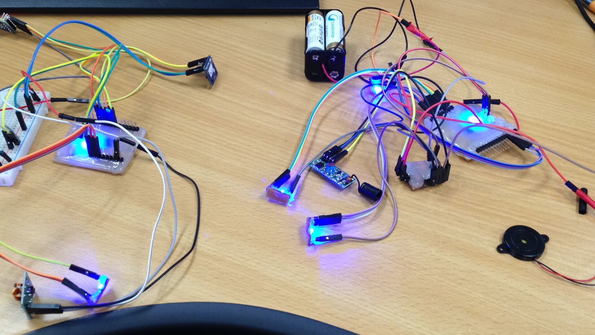
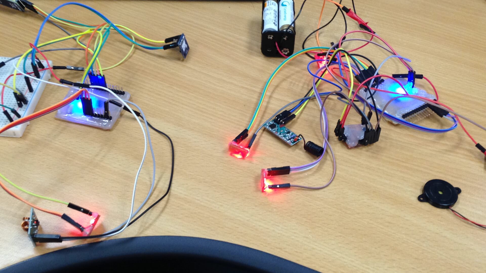
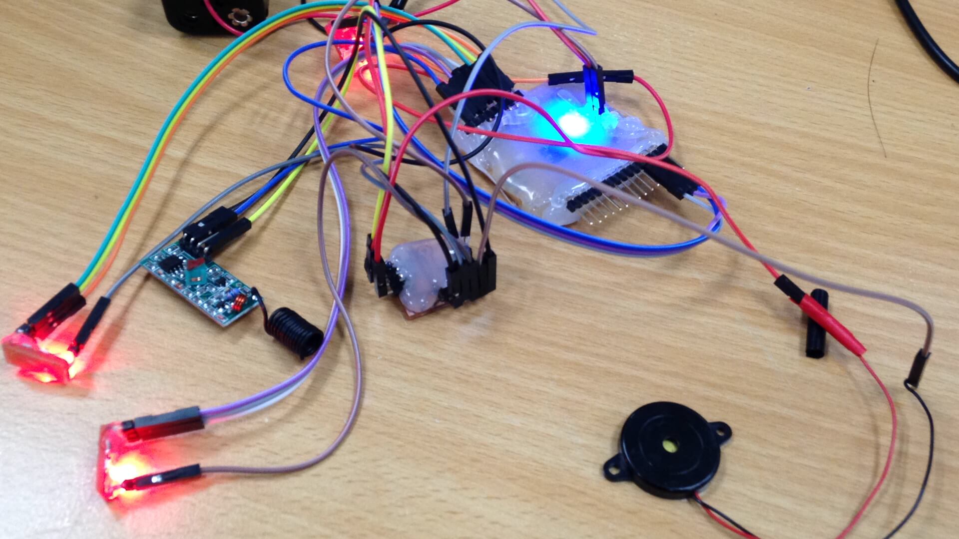
The program consists of a transmitter that sends a signal when a input device(ADXL345) detect gravitational acceleration and a receiver which is waiting the information. When the receiver receive a signal from transmitter then LED will change color and you can hear buzzer(output devices).
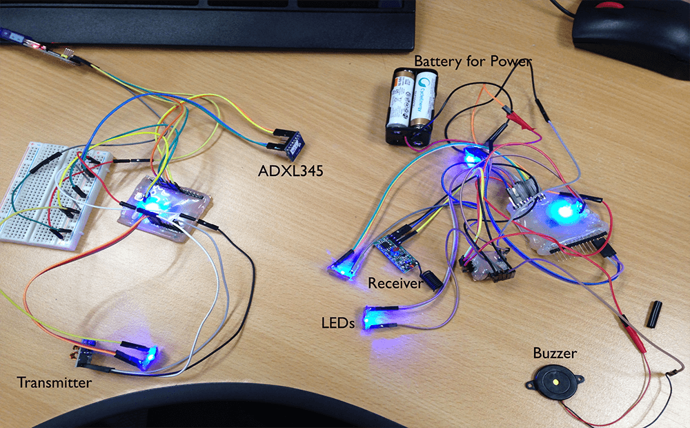
Original LED color is blue. When the ADXL345 detect gravitational acceleration will change LED color to RED and hear the buzzer.
I used VirtualWire llibrary for RF433MHz. VirtualWire is an Arduino library that provides features to send short messages, without addressing. Some explanation with code.
To select the Transmitter data pin.
vw_set_tx_pin
To select the Receiver data pin.
vw_set_rx_pin
Setup the speed of transmission.
vw_setup(uint16_t speed);
Block and wait until the transmitter is idle.
vw_wait_tx();
Block and wait until a message is available from the receiver.
vw_wait_rx();
Send a message with the given length.
vw_send(uint8_t* buf, uint8_t len);
When the ADXL345 detect acceleration then it will send character 'A'.
send("A");
void send (char *message)
{
vw_send((uint8_t *)message, strlen(message));
vw_wait_tx();
}
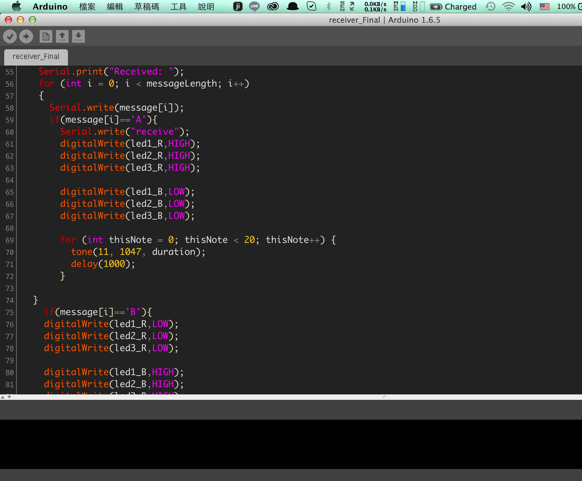
When the receiver received character'A', you can hear buzzer and LED change color to RED.
vw_get_message(message, &messageLength)
if(message[i]=='A')
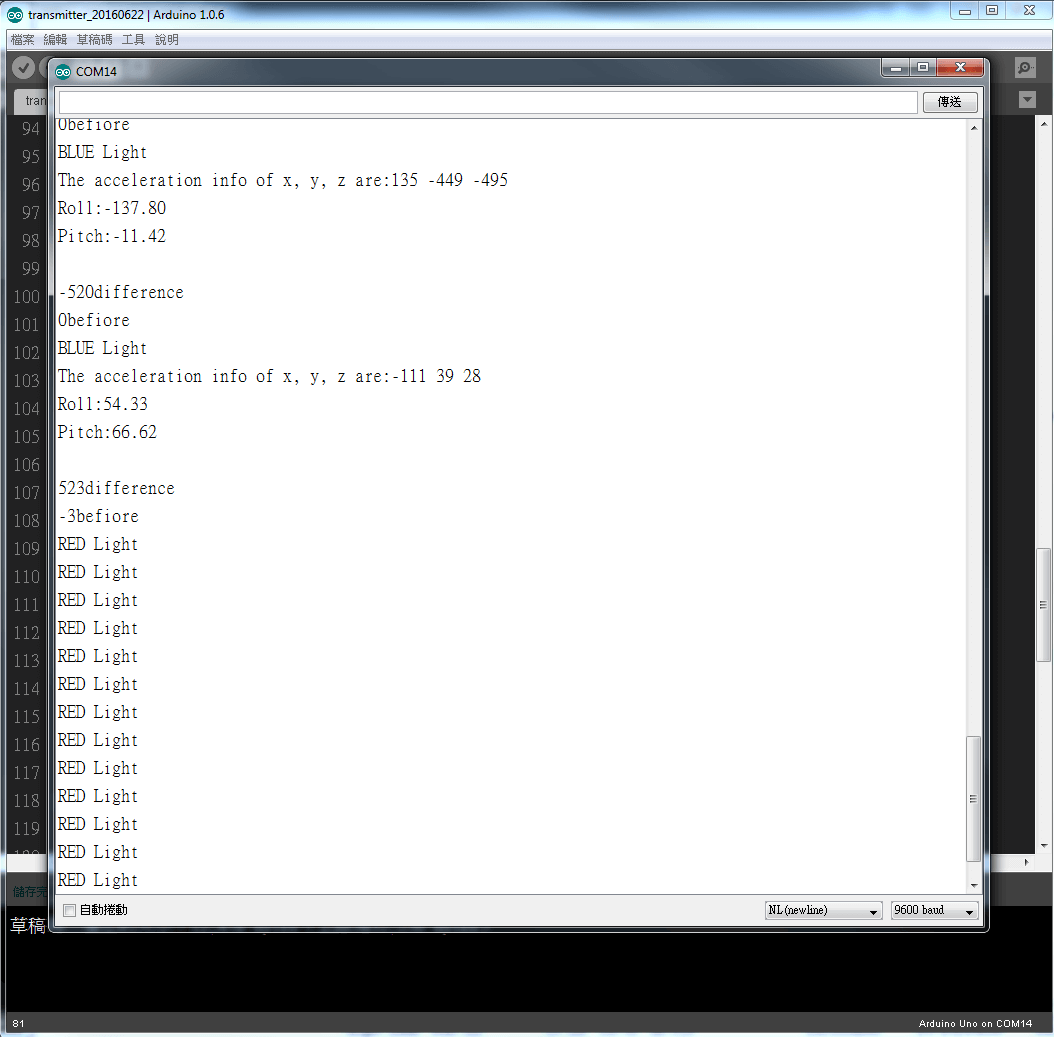
So I recognized status by different character that receiver received.
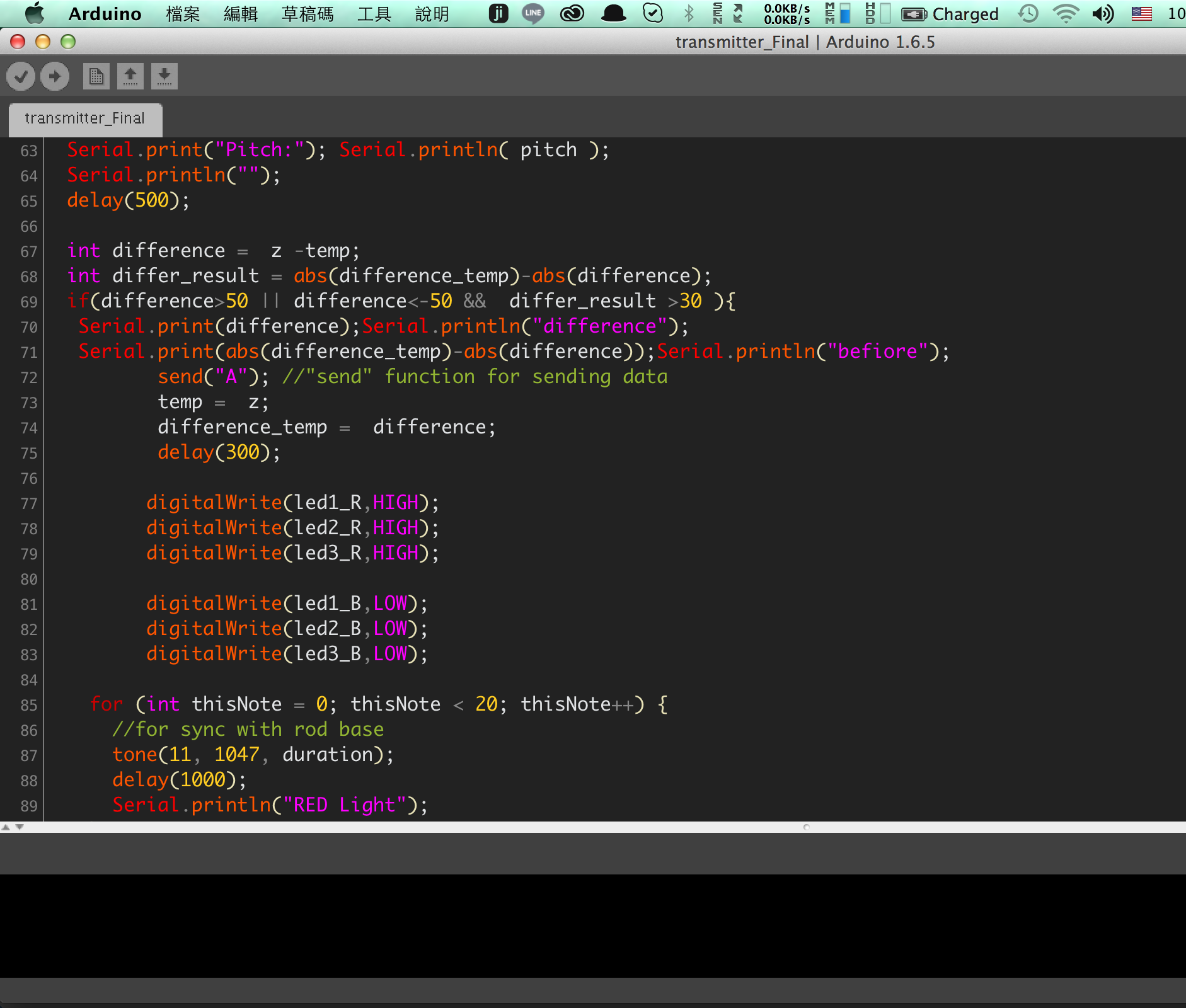
Programming in transmitter:
#include#include #define DEVICE (0x53) #define TO_READ (6) byte buff[TO_READ] ; char str[512]; int regAddress = 0x32; int x, y, z; double roll = 0.00, pitch = 0.00; int led1_R=2; int led1_G=3; int led1_B=4; int led2_R=5; int led2_G=6; int led2_B=7; int led3_R=8; int led3_G=10; int led3_B=9; int temp = 0; int difference_temp=0; int duration = 50; void setup() { vw_setup(2000); vw_set_tx_pin(12); Wire.begin(); Serial.begin(9600); writeTo(DEVICE, 0x2D, 0); writeTo(DEVICE, 0x2D, 16); writeTo(DEVICE, 0x2D, 8); pinMode(led1_R,OUTPUT); pinMode(led1_G,OUTPUT); pinMode(led1_B,OUTPUT); pinMode(led2_R,OUTPUT); pinMode(led2_G,OUTPUT); pinMode(led2_B,OUTPUT); pinMode(led3_R,OUTPUT); pinMode(led3_G,OUTPUT); pinMode(led3_B,OUTPUT); } void loop() { readFrom(DEVICE, regAddress, TO_READ, buff); x = (((int)buff[1]) << 8) | buff[0]; y = (((int)buff[3])<< 8) | buff[2]; z = (((int)buff[5]) << 8) | buff[4]; Serial.print("The acceleration info of x, y, z are:"); sprintf(str, "%d %d %d", x, y, z); Serial.print(str); Serial.write(10); RP_calculate(); Serial.print("Roll:"); Serial.println( roll ); Serial.print("Pitch:"); Serial.println( pitch ); Serial.println(""); delay(500); int difference = z -temp; int differ_result = abs(difference_temp)-abs(difference); if(difference>50 || difference<-50 && differ_result >30 ){ Serial.print(difference);Serial.println("difference"); Serial.print(abs(difference_temp)-abs(difference));Serial.println("befiore"); send("A"); //"send" function for sending data temp = z; difference_temp = difference; delay(300); digitalWrite(led1_R,HIGH); digitalWrite(led2_R,HIGH); digitalWrite(led3_R,HIGH); digitalWrite(led1_B,LOW); digitalWrite(led2_B,LOW); digitalWrite(led3_B,LOW); for (int thisNote = 0; thisNote < 20; thisNote++) { //for sync with rod base tone(11, 1047, duration); delay(1000); Serial.println("RED Light"); } } else if(difference<50 || difference>-50 && differ_result <30){ difference_temp = difference; Serial.print(difference);Serial.println("difference"); Serial.print(abs(difference_temp)-abs(difference));Serial.println("befiore"); send("B"); //"send" function for sending data temp = z; delay(300); digitalWrite(led1_R,LOW); digitalWrite(led2_R,LOW); digitalWrite(led3_R,LOW); digitalWrite(led1_B,HIGH); digitalWrite(led2_B,HIGH); digitalWrite(led3_B,HIGH); Serial.println("BLUE Light"); } } void send (char *message) { vw_send((uint8_t *)message, strlen(message)); vw_wait_tx(); } void writeTo(int device, byte address, byte val) { Wire.beginTransmission(device); Wire.write(address); Wire.write(val); Wire.endTransmission(); } void readFrom(int device, byte address, int num, byte buff[]) { Wire.beginTransmission(device); Wire.write(address); Wire.endTransmission(); Wire.beginTransmission(device); Wire.requestFrom(device, num); int i = 0; while(Wire.available()) { buff[i] = Wire.read(); i++; } Wire.endTransmission(); } void RP_calculate(){ double x_Buff = float(x); double y_Buff = float(y); double z_Buff = float(z); roll = atan2(y_Buff , z_Buff) * 57.3; pitch = atan2((- x_Buff) , sqrt(y_Buff * y_Buff + z_Buff * z_Buff)) * 57.3; }
RF433Mhz module with ADXL345 Sensor(input devices) and LED and Buzzer Sensor(Output devices).
The code is the same with final code.