Week 13::Output Devices
Learning outcomes: Demonstrate work flows used in circuit board design and fabrication. Implement and interpret programming protocols. Source Files.
Demonstrate work flows used in circuit board design and fabrication:
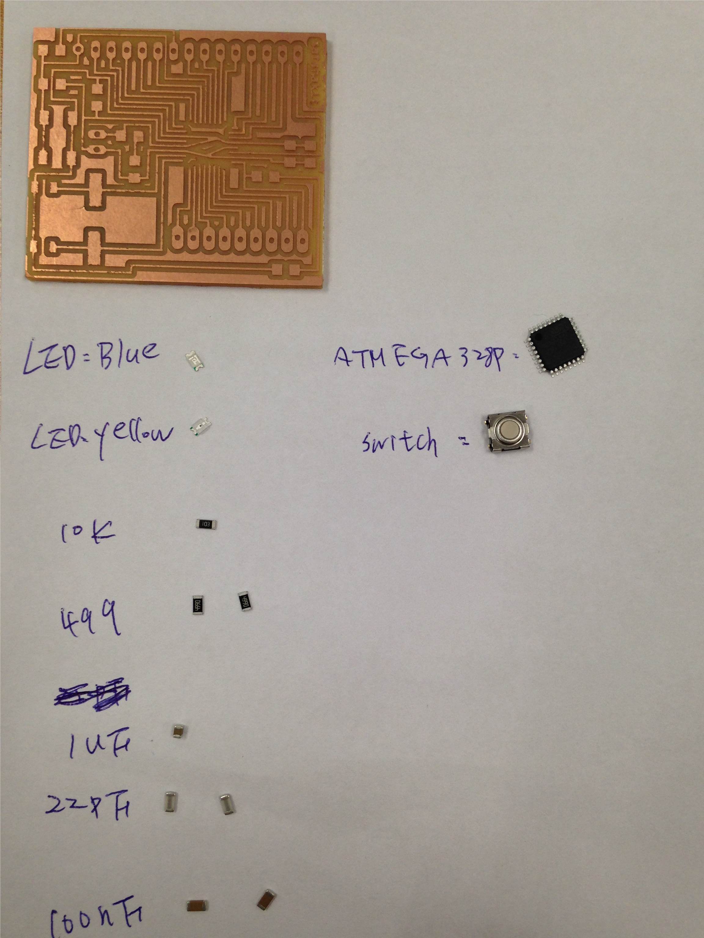
This week I made satshaKit and satshakit micro and LED board for my output device control.
Start soldering with components:
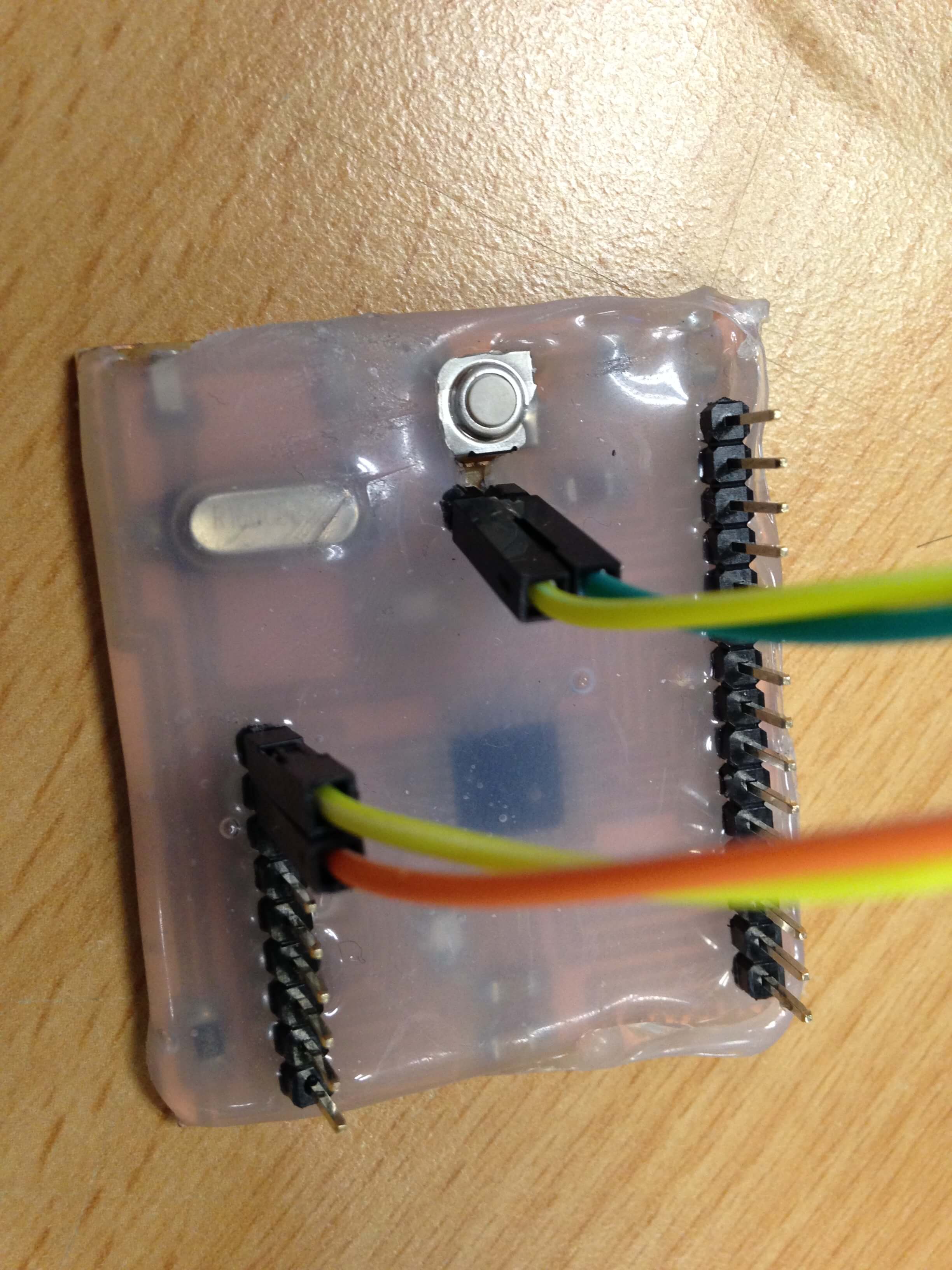
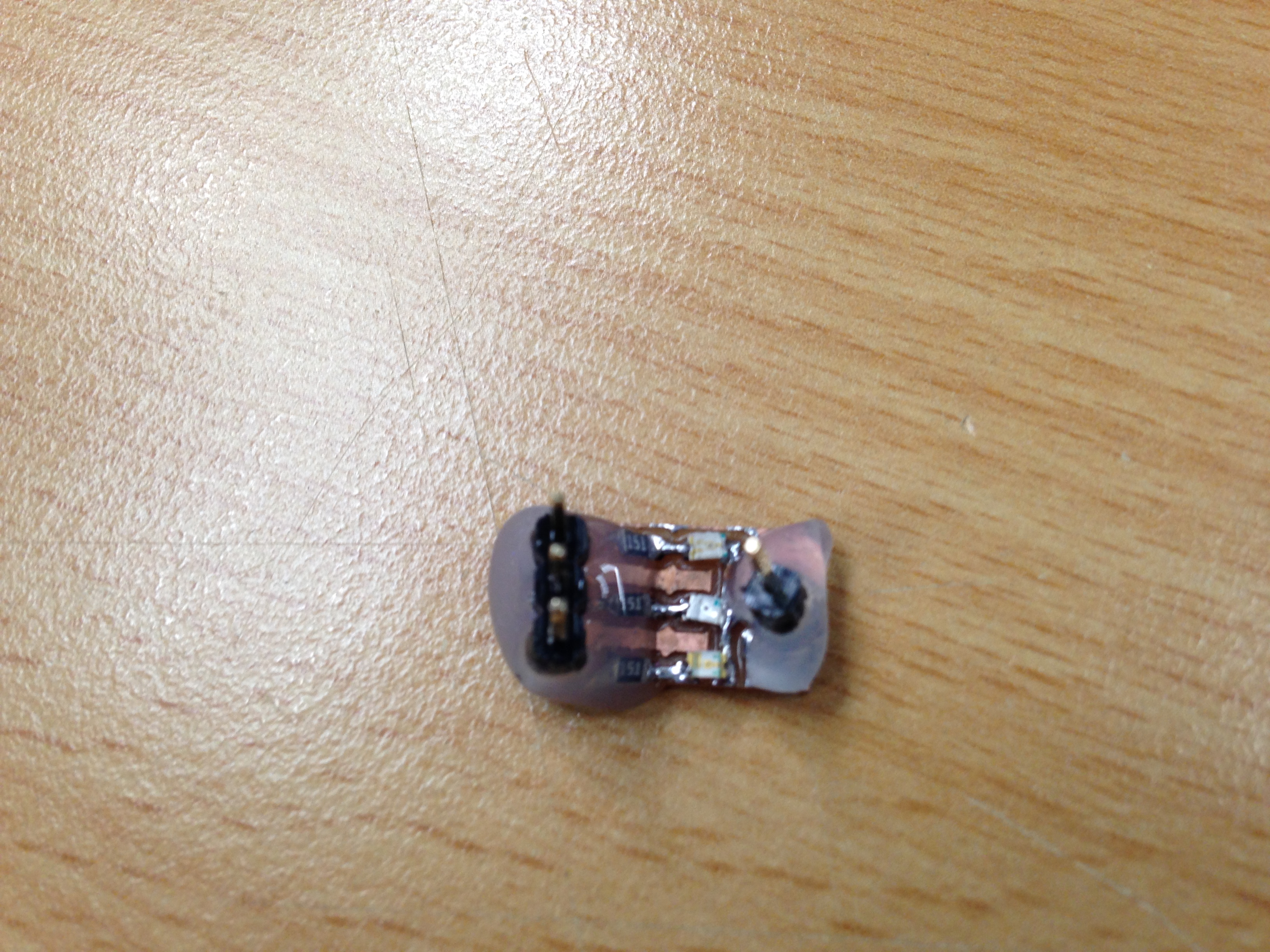
After soldering, I was used hot glue gun to protect this board.
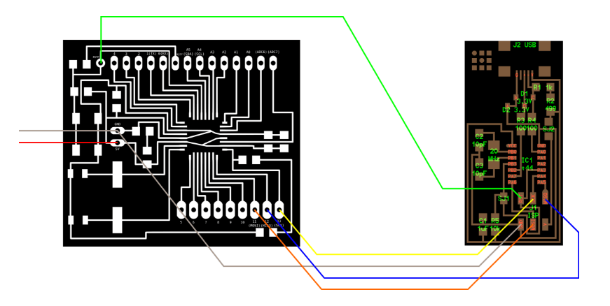
Following satshaKit tutorial, I am ready to program it.
I am using my FabISP be a programmer to upload Arduino bootloader.
Follow these steps to upload Arduino bootloader:
Then satsha kit board is totally like an Arduino board.
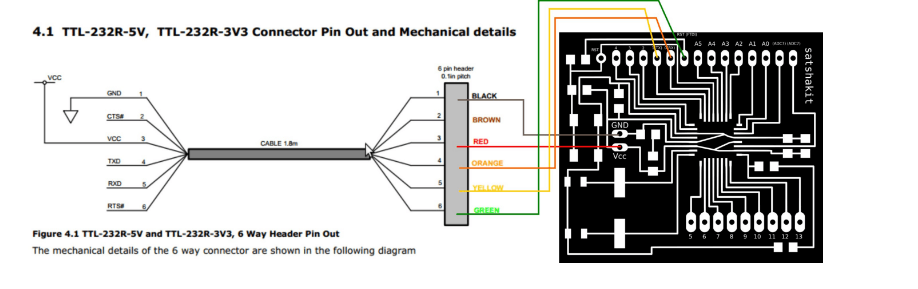
I can use FTDI USB cable to upload and use my sketch without the need to use a programmer.
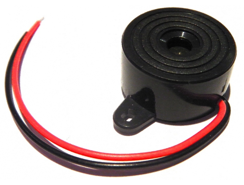
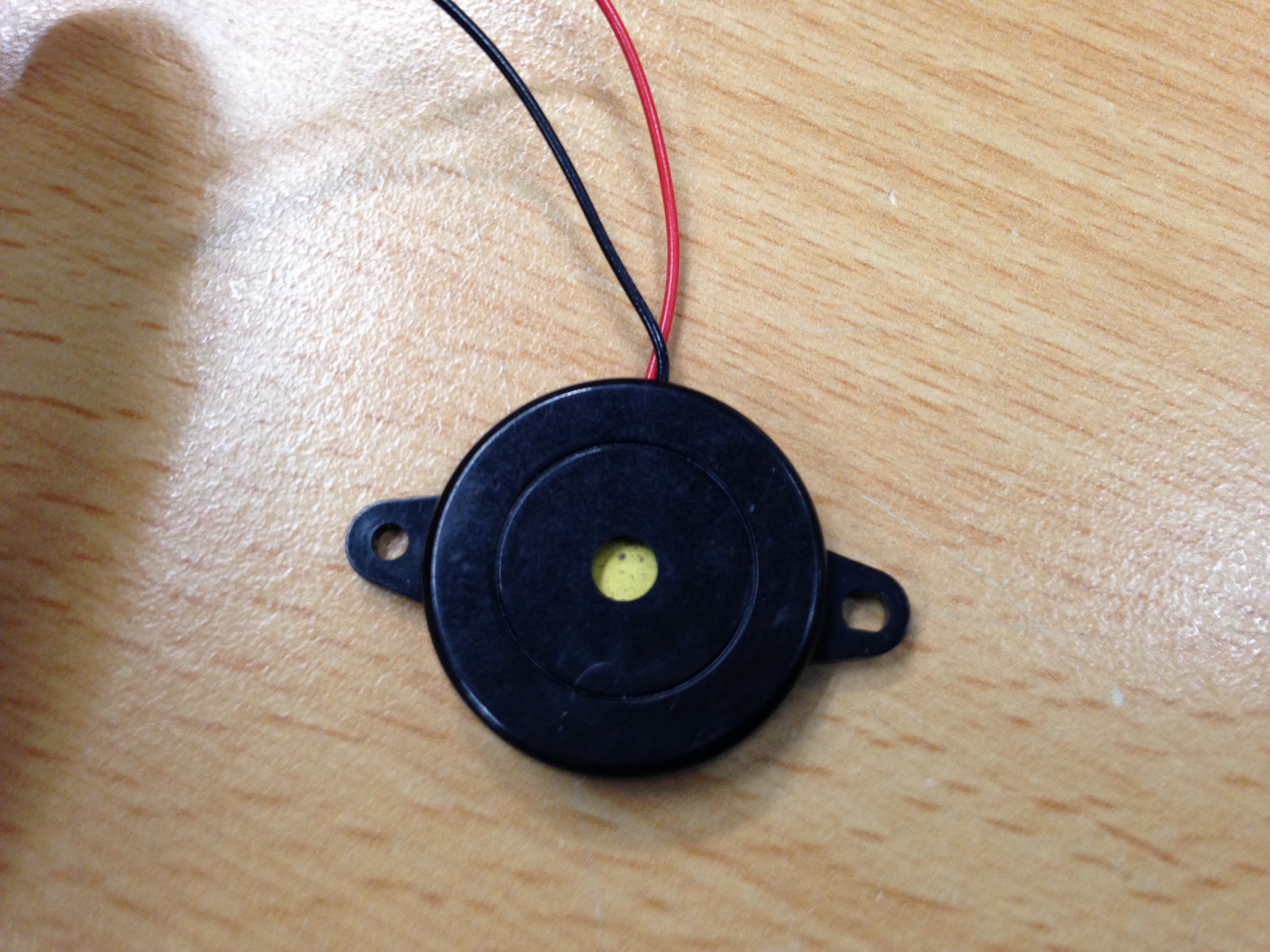
A buzzer is an audio signalling device, which may be mechanical, electromechanical, or piezoelectric. So I want to use buzzer to make a signal to help people to know when is the perfect timing to set a hook in my final project.
Implement and interpret programming protocols:
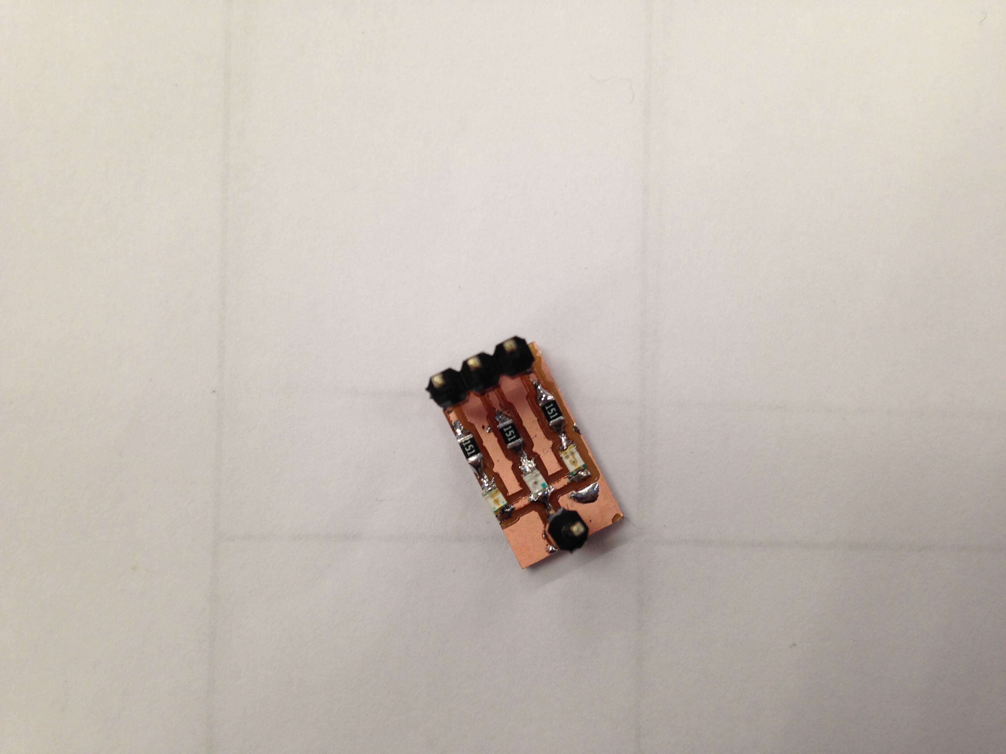
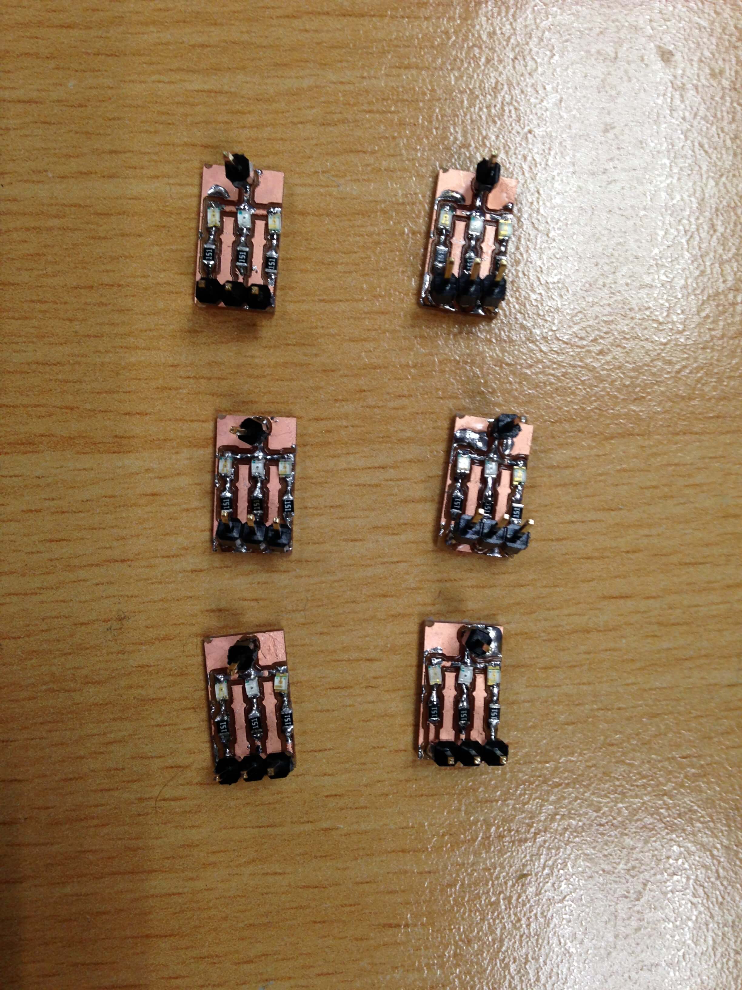
I made LED board be a output device for fishing float and rod base. Also I used hot glue gun to protect this board.
So I can control LED color at the same time.
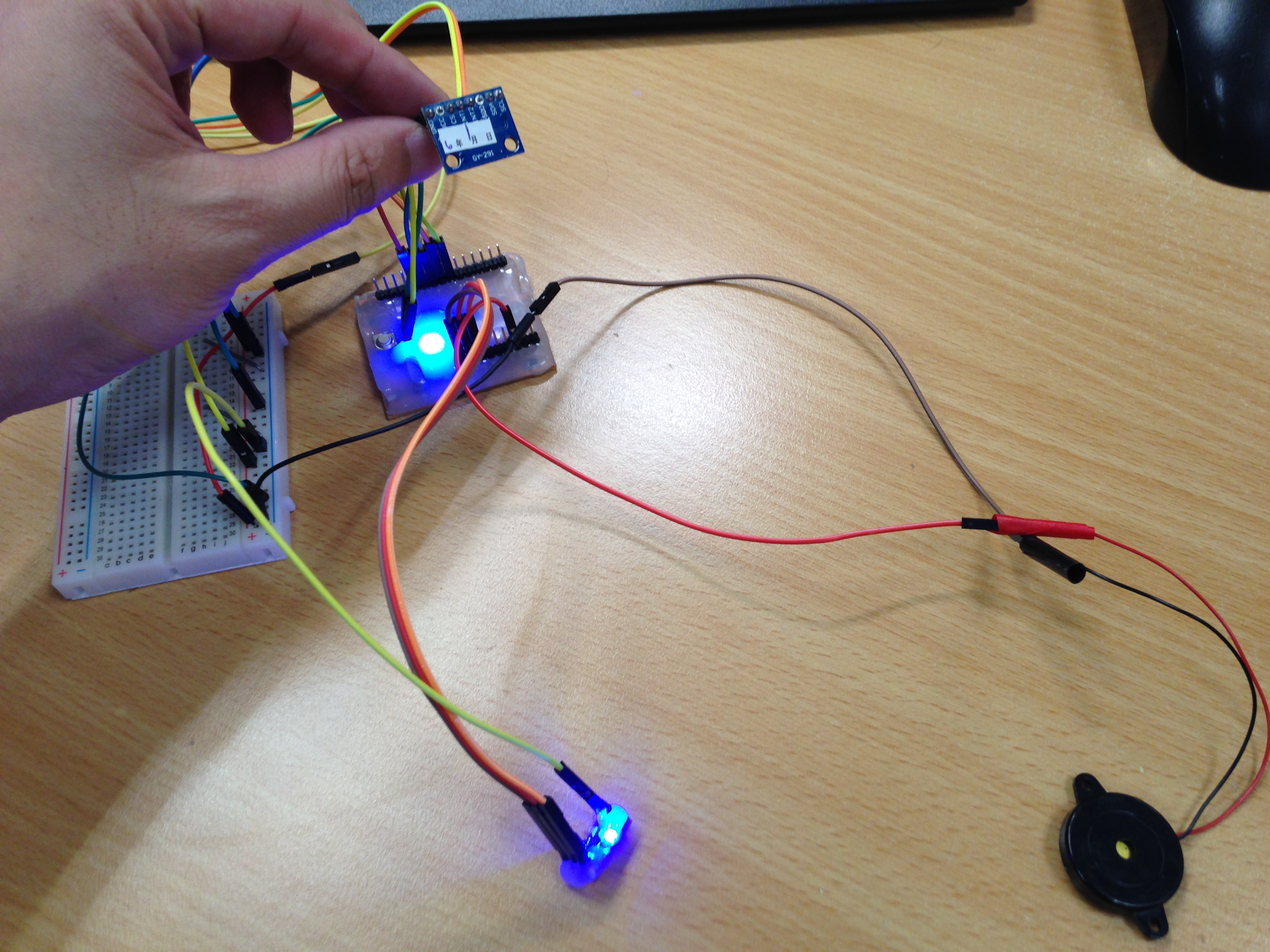
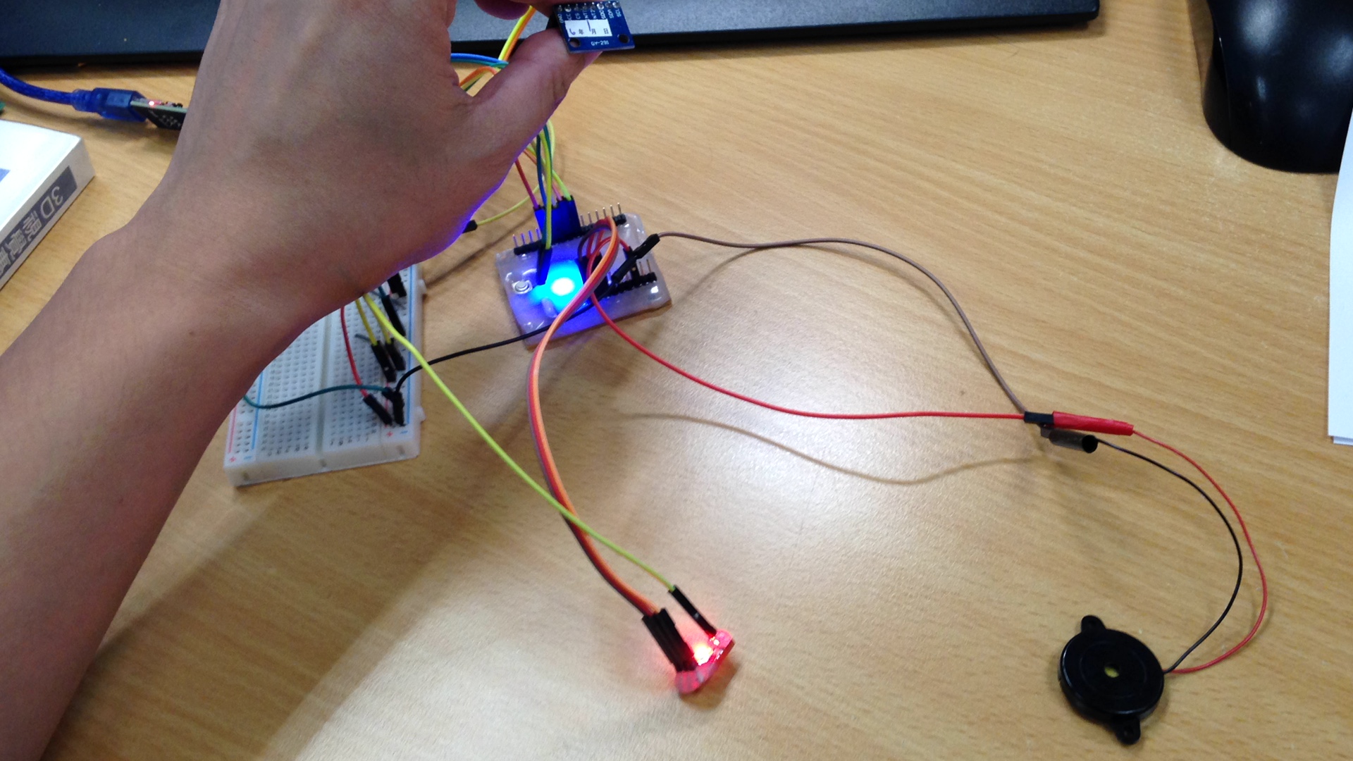
In this week assignment when ADXL345(input) detect gravitational acceleration then LED will change color to RED and you can hear buzzer(output devices).
Used hot glue to protect board.
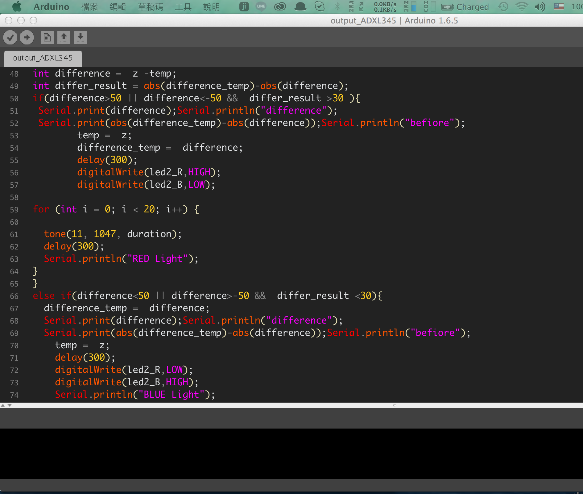
Some explanation with code.
int difference = z -temp;
int differ_result = abs(difference_temp)-abs(difference);
if(difference>50 || difference<-50 && differ_result >30 )
I received Z-axis value from ADXL345 every second. So I used the difference between two value(this time and last time) larger threshold value then send a signal to rod base.
Trial and error is a fundamental method of solving problems or finding threshold. Finally I used 50 to judge fish bite the bait. It is very specific but not very sensitive.
Video with ADXL345 Sensor(input devices) and LED and Buzzer Sensor(Output devices).
As you can see the video. This is my final project code, so when the ADXL345 detects gravitational acceleration(I was used the difference with last time) then will send a signal and change LED color to RED.