Week 11::Input Devices
Learning outcomes: Demonstrate work flows used in circuit board design and fabrication. Implement and interpret programming protocols. Source Files.
Demonstrate work flows used in circuit board design and fabrication:
Making satshaKit for my input device control.
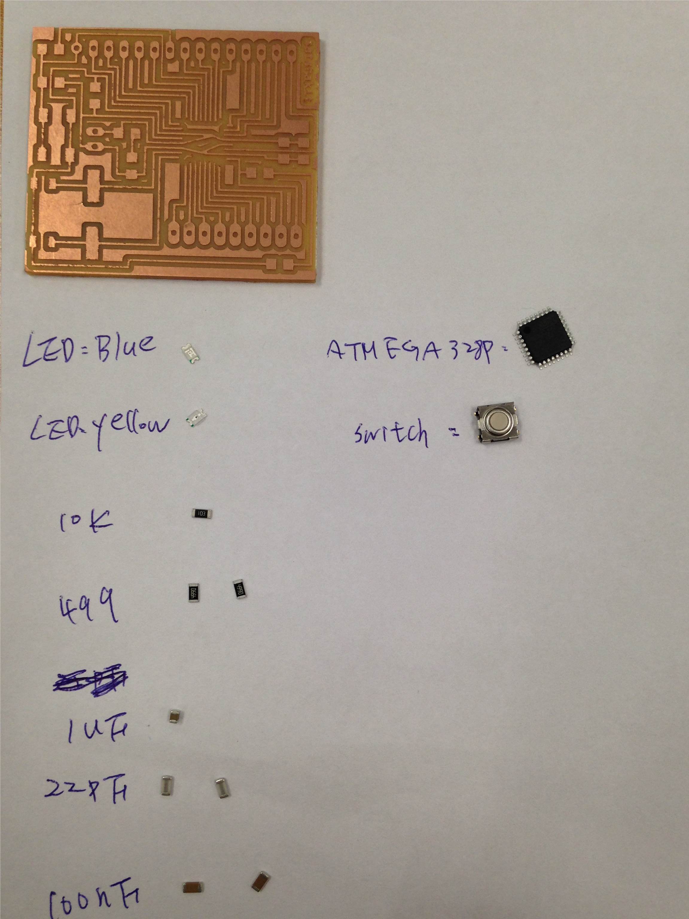
Start soldering with components:
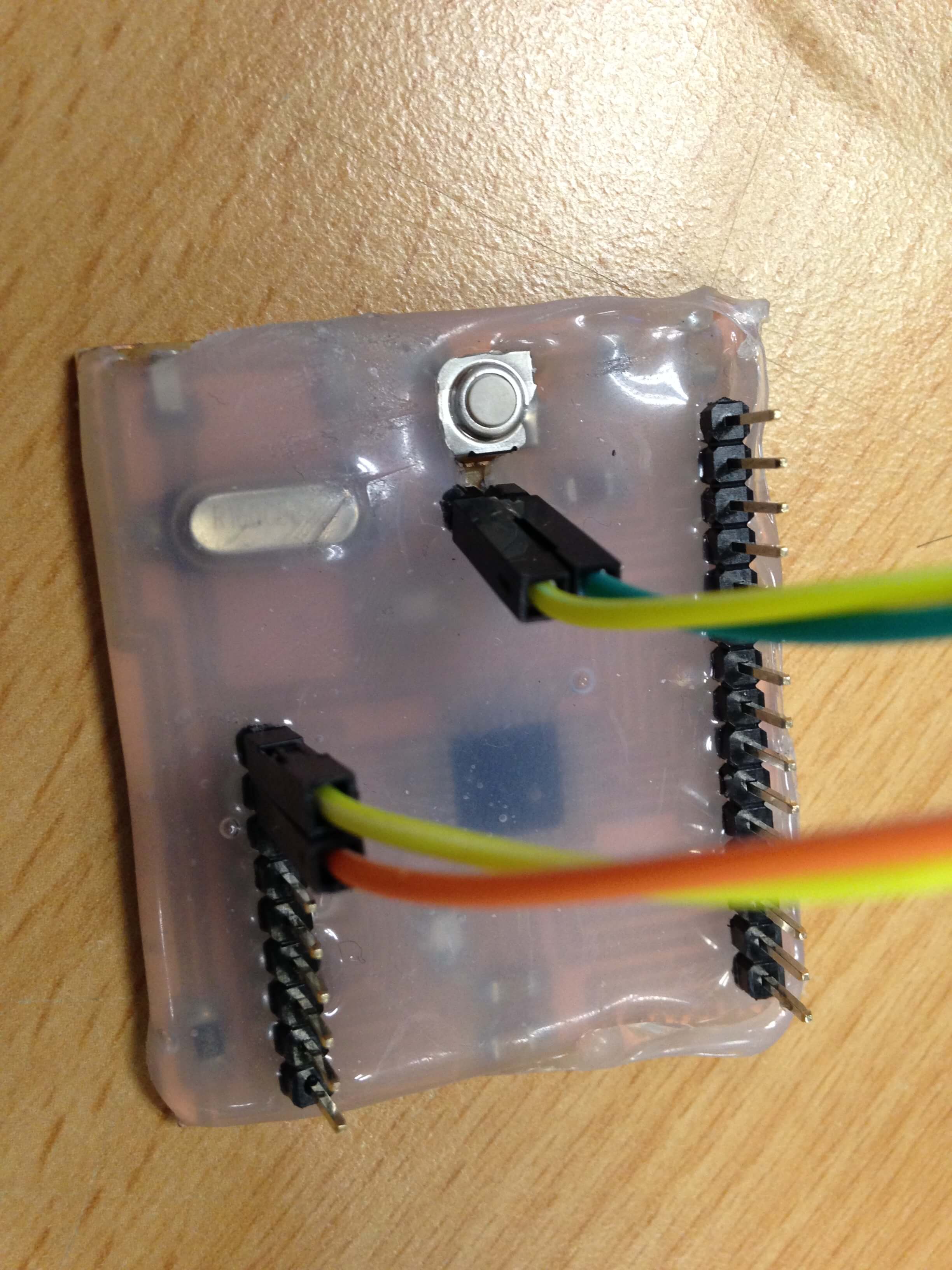
After soldering, I was used hot glue gun to protect this board.
Following satshaKit tutorial, I am ready to program it.
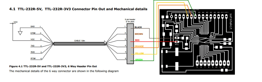
I am using my FabISP be a programmer to upload Arduino bootloader.
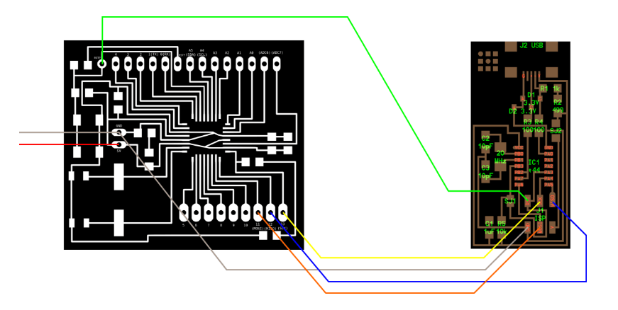
Follow these steps to upload Arduino bootloader:
Then satsha kit board is totally like an Arduino board.
I can use FTDI USB cable to upload and use my sketch without the need to use a programmer.
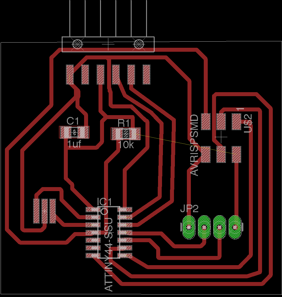
Then I tried to use attiny44a to design electronic board with eagle.
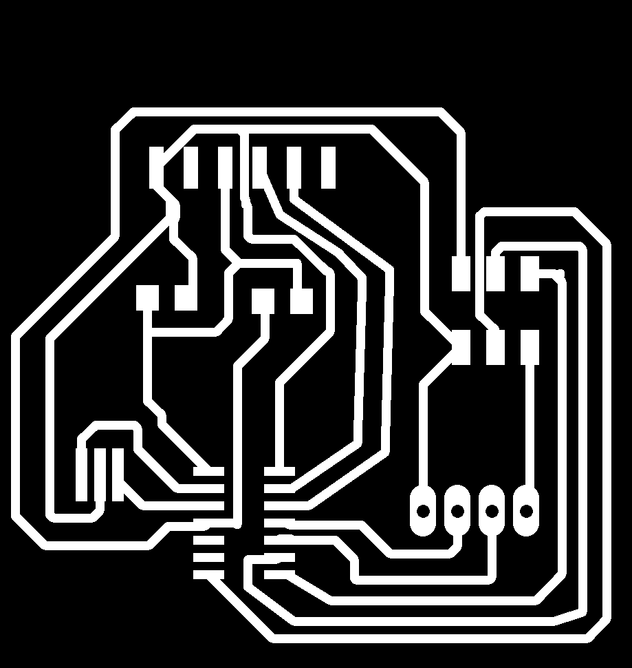
I used GIMP to generate border for board.

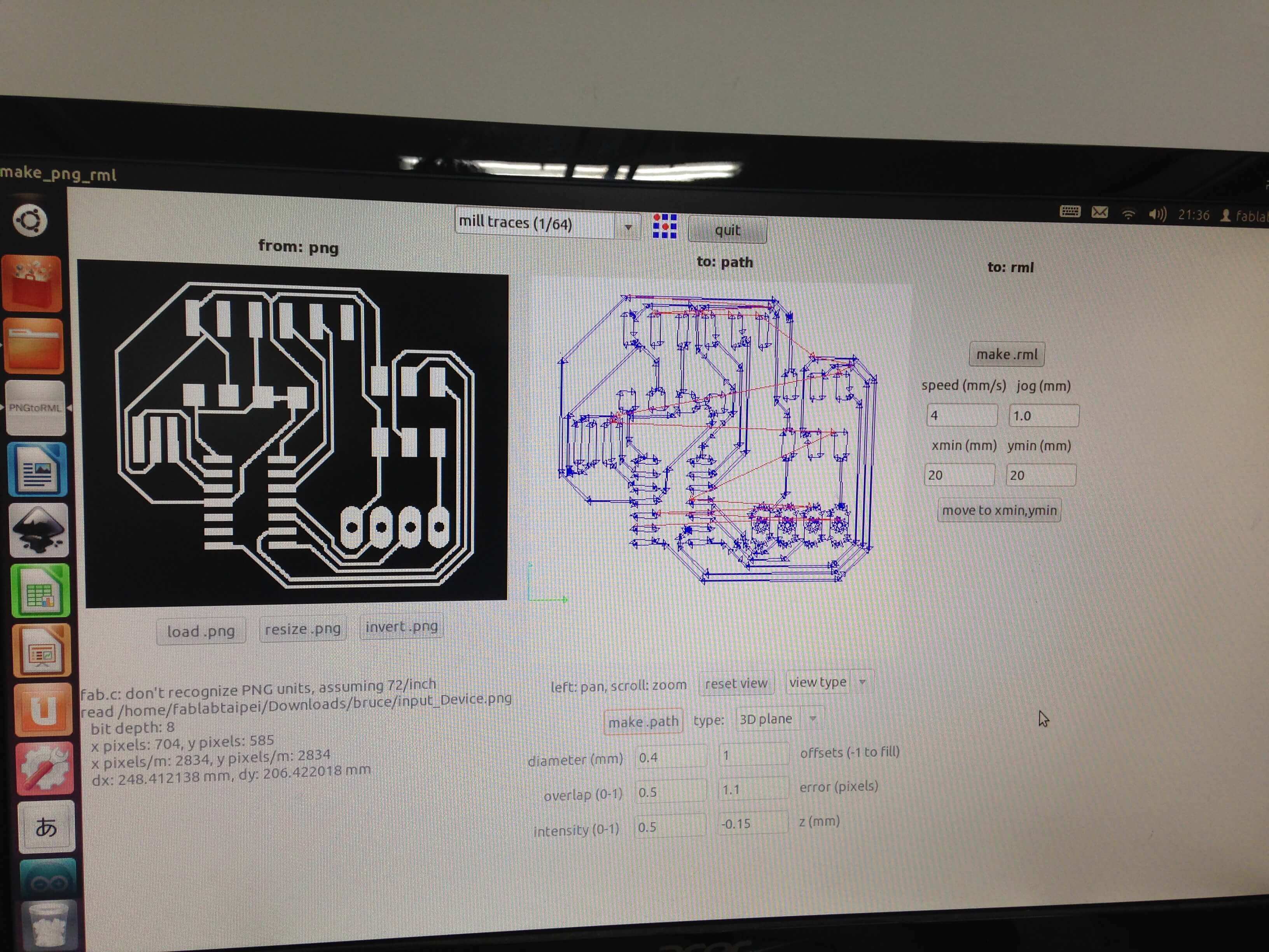
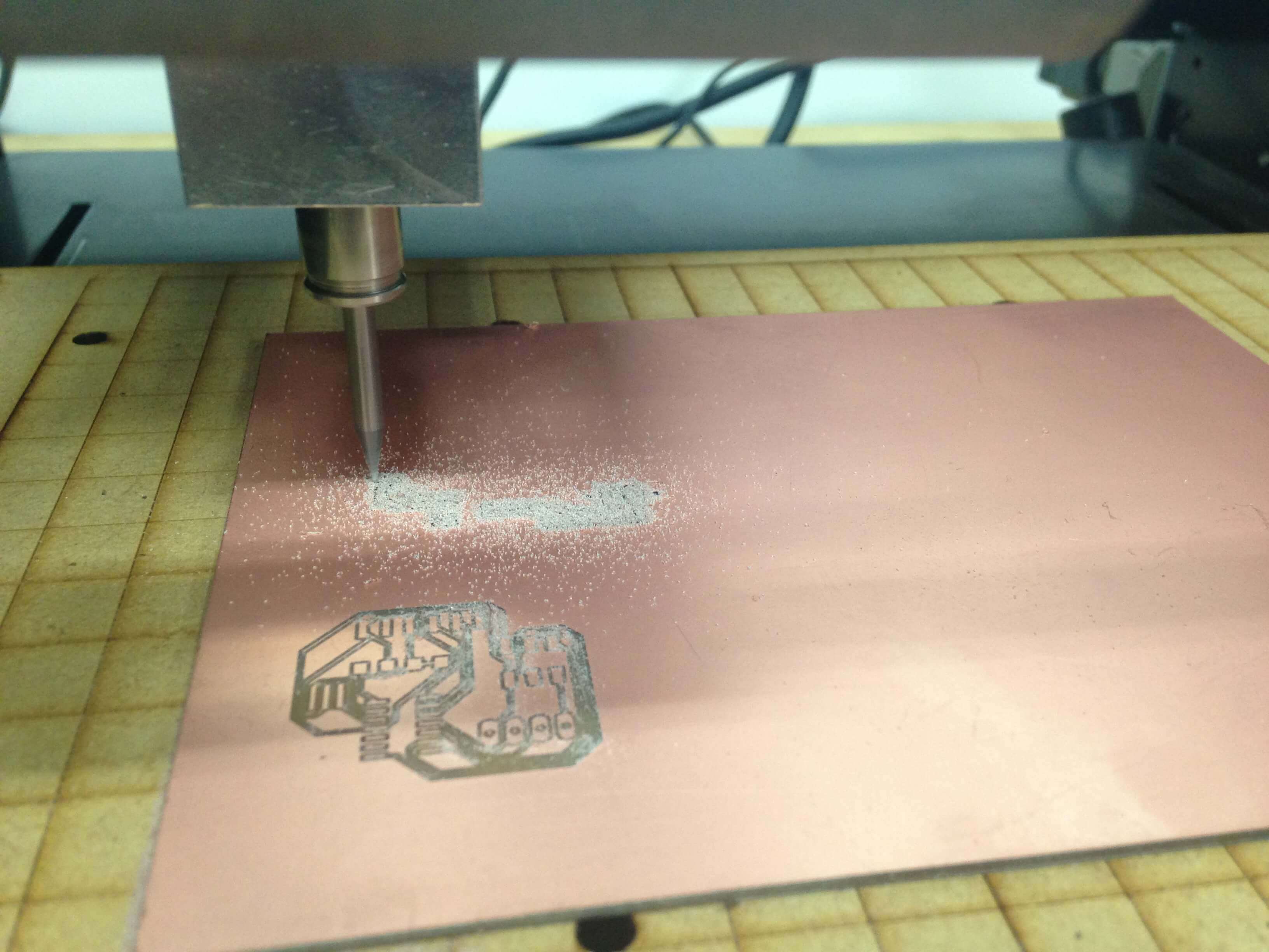
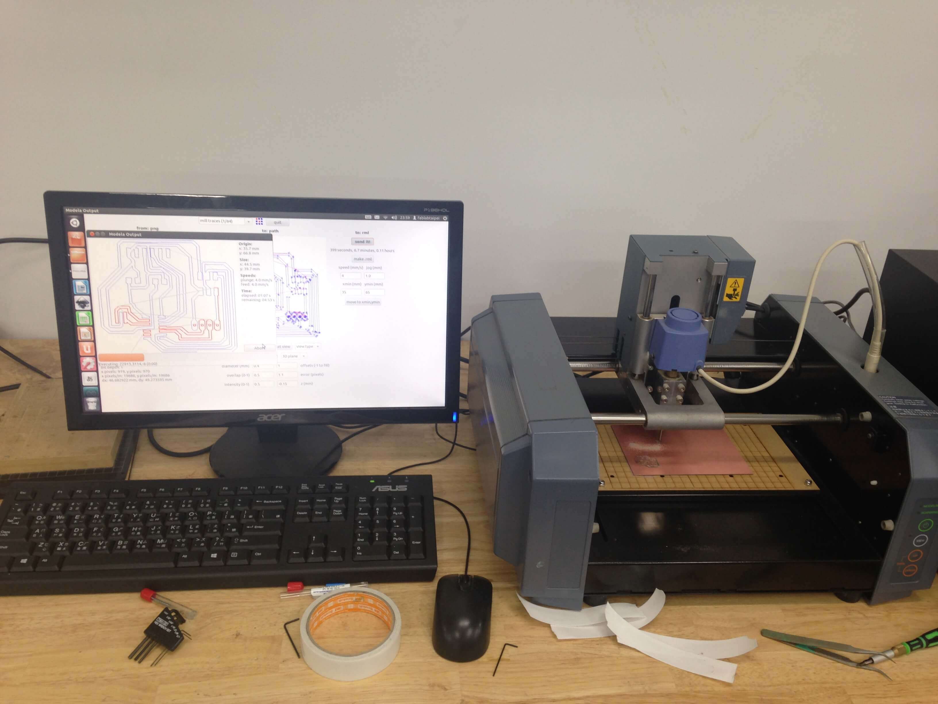
For milling the traces board. The variable what is set:
Milling the traces:
diameter(mm):0.4; Offsets:2
Overlap:0.5; error(pixels):1.1
intensity:0.5; z(mm):-0.15
Milling the border:
diameter(mm):0.79; Offsets:2
Overlap:0.5; error(pixels):1.1
top intensity:0.5; top z(mm):-0.8
bot intensity:0.5; bot z(mm):-1.9
cut depth(mm):1.7
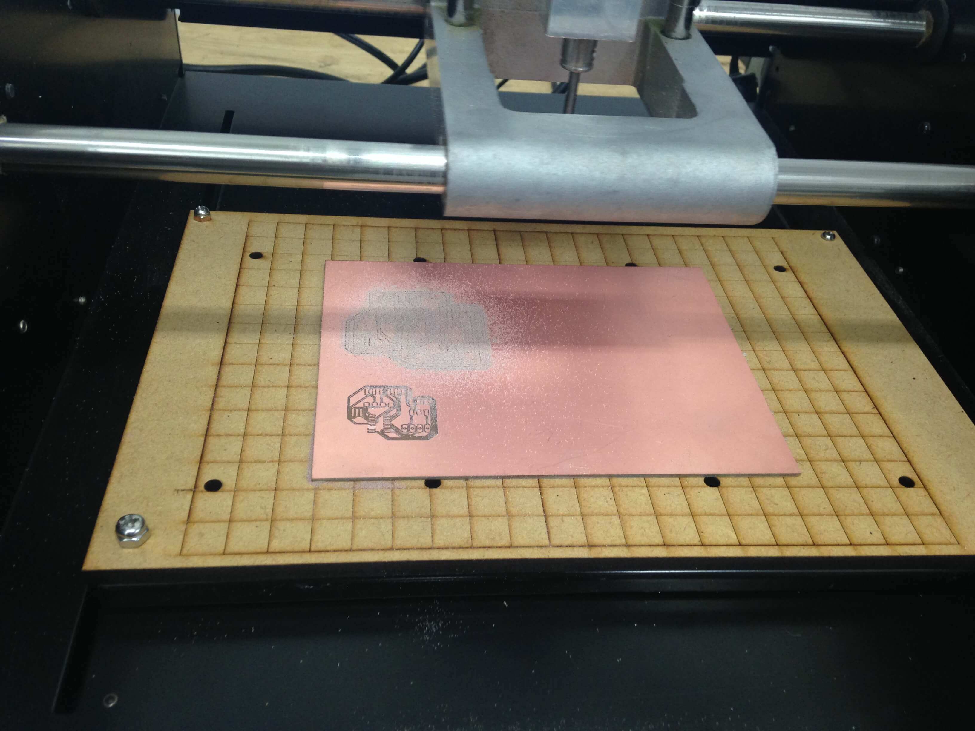
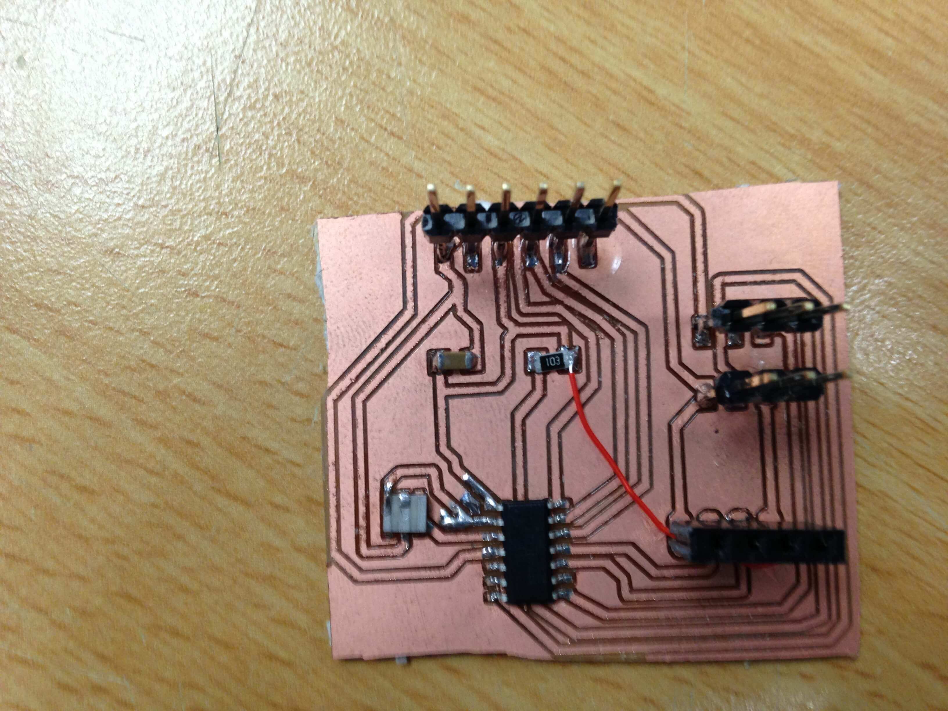
After milling the board, start to soldering the board.
Solder electronic components:
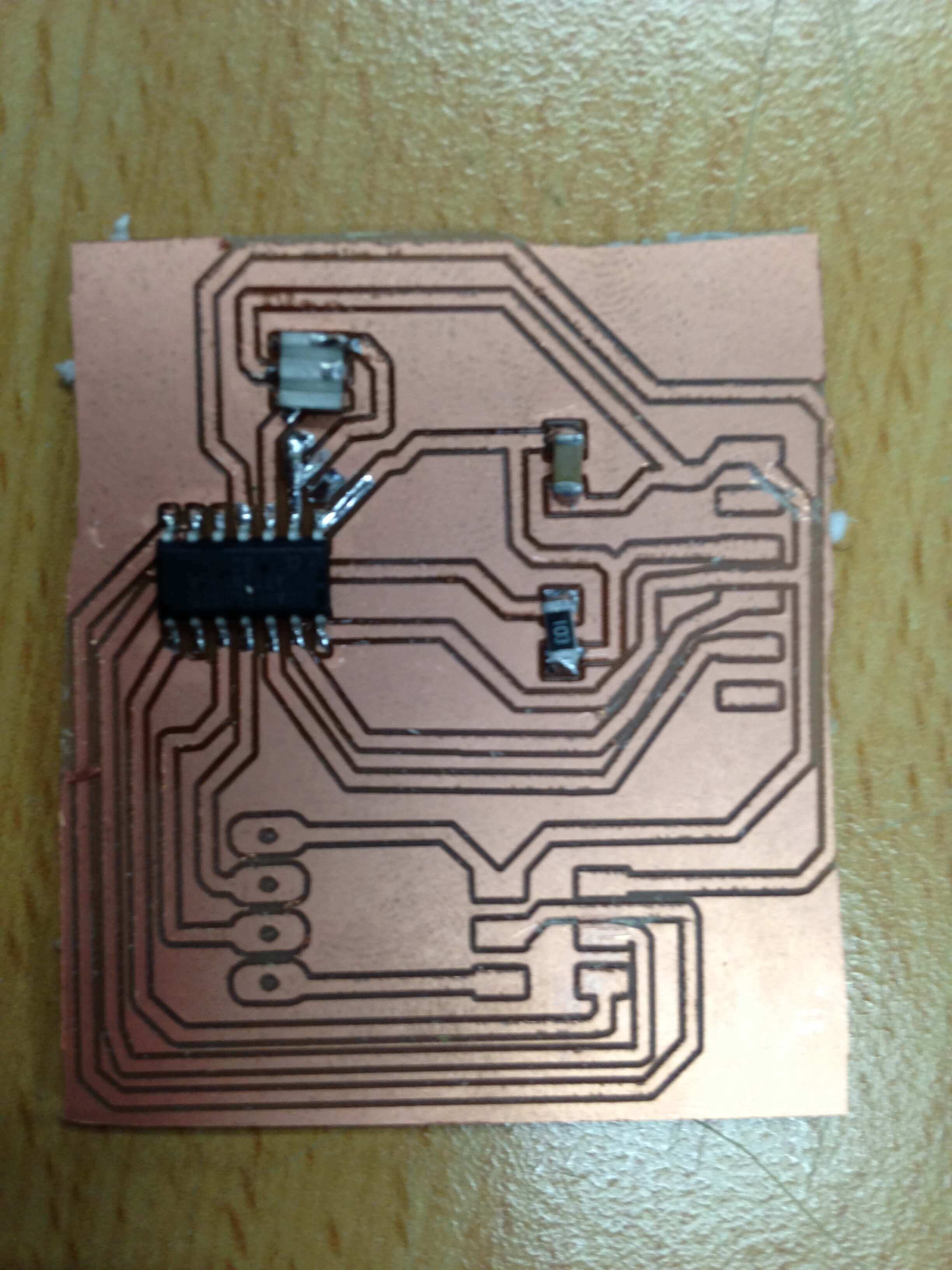
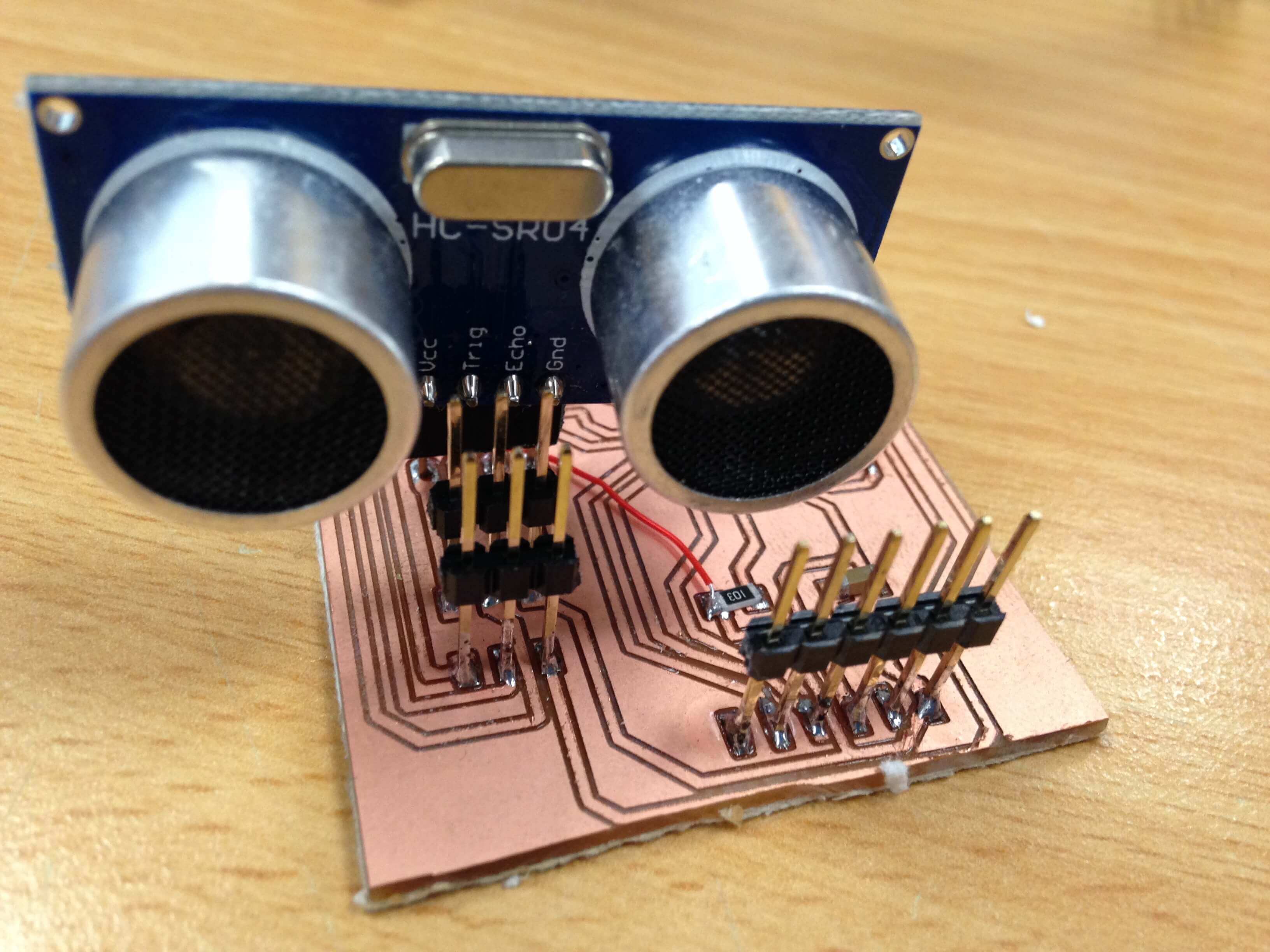
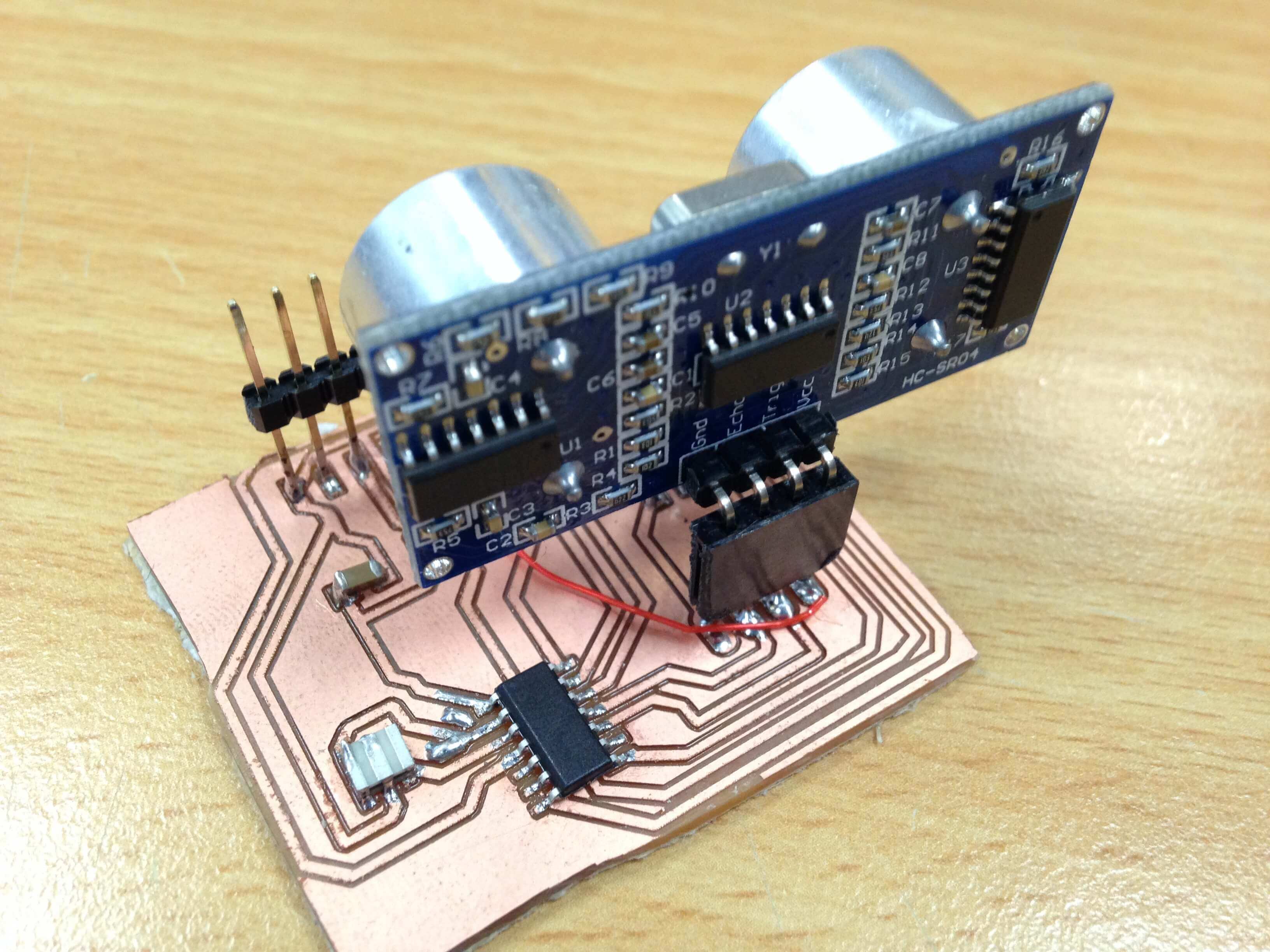
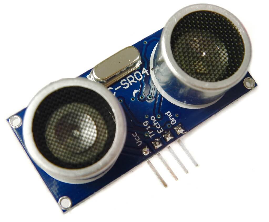
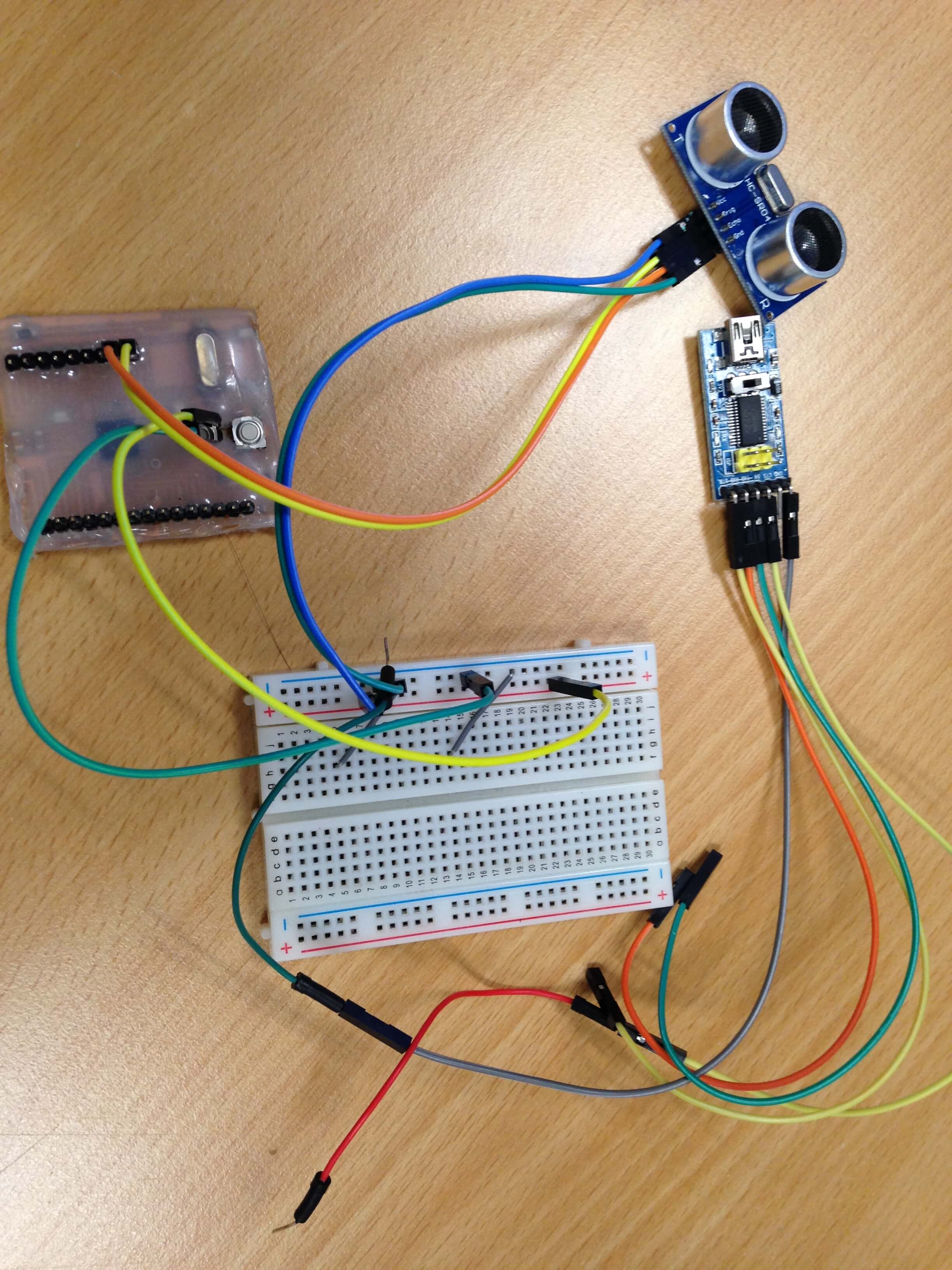
After soldering the board, combination with HC-SR04 Ultrasonic Sensor.
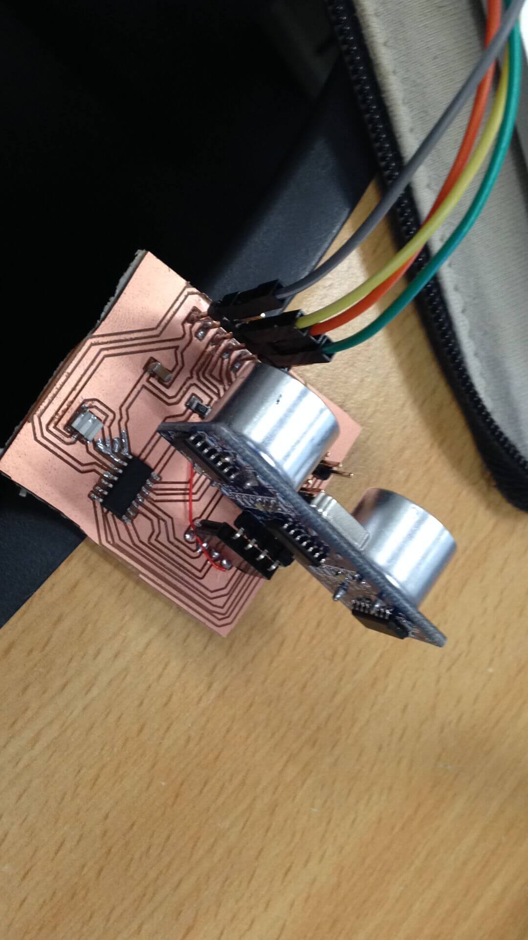
Video with Ultrasonic Sensor, Arduino IDE and my board.
The HC-SR04 Ultrasonic Sensor is a very affordable distance sensor that has been used mainly for object avoidance in various robotics projects. It has also been used in turret applications, water level sensing, and even as a parking sensor. To use this sensor to measure distance for input device assignment.
Video with Ultrasonic Sensor and Arduino IDE.
Implement and interpret programming protocols:
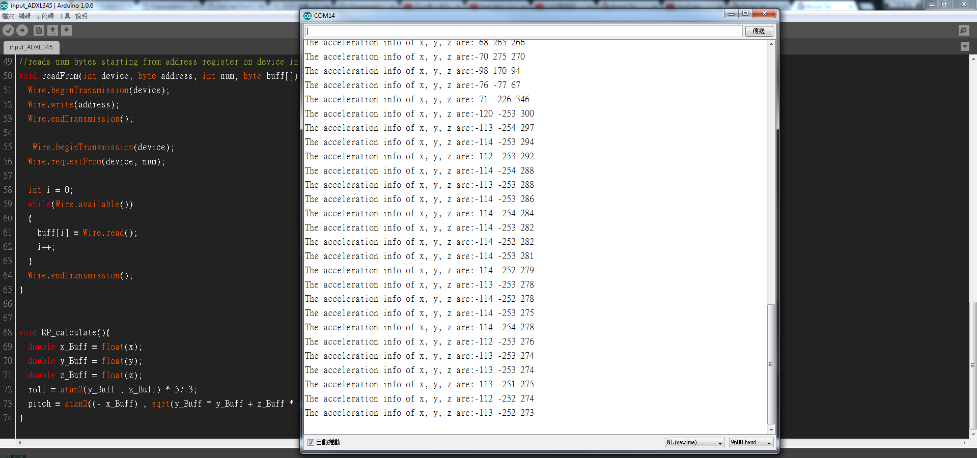
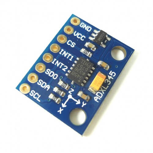
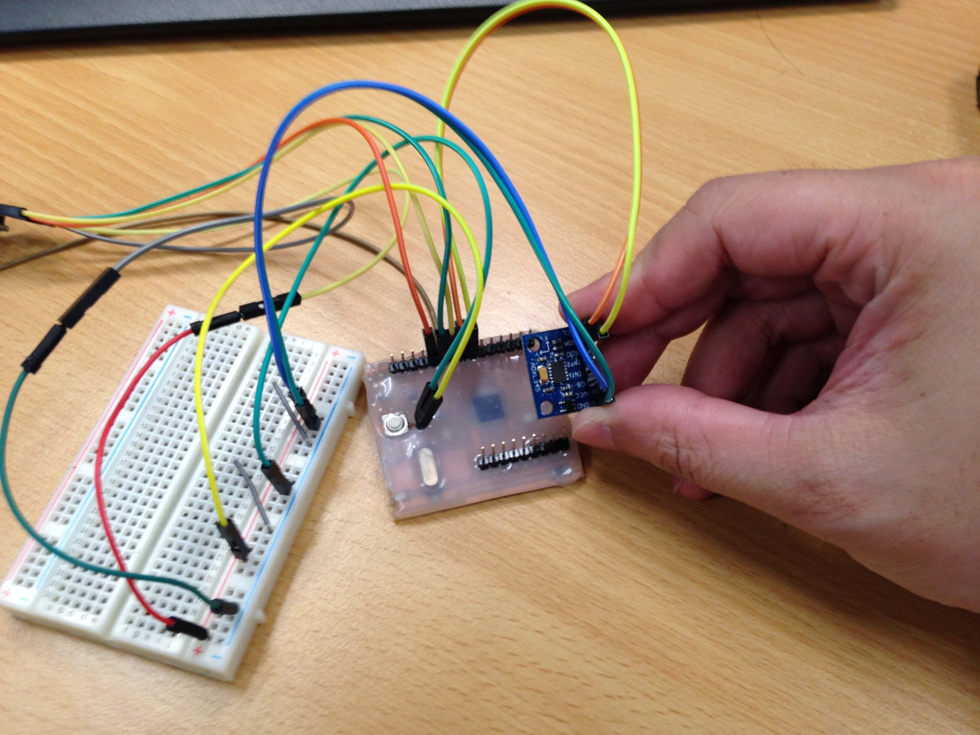
In my final project, I was made a fishing float to help people when is the perfect timing to set a hook. So I put ADXL345 into the fishing float to detect gravitational acceleration.
The ADXL345 has three axes of measurements, X Y Z, and pins that can be used either as I2C or SPI digital interfacing. I can set the sensitivity level to either +-2g, +-4g, +-8g or +-16g. The lower range gives more resolution for slow movements, the higher range is good for high speed tracking. So I was used it to detect gravitational acceleration.
I used wire llibrary for ADXL345. Some explanation with code.
Wire.begin();
For I2C initalize.
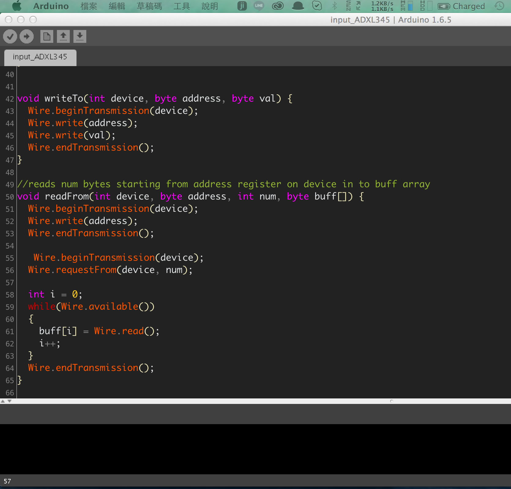
void writeTo(int device, byte address, byte val)
Write data to reguster.
void readFrom(int device, byte address, int num, byte buff[])
Read data form ADXL345. For example: X, Y, Z values.
Video with ADXL345 Sensor and Arduino IDE.