Embedded Programming
This week would be really challenging, to setup entire AVR microcontroller programming workflow. Though I have some coding experiences, but never really do any programming on MCU-level hardware except Arduinos.
Datasheet is always bulky and tedious. But it is this heavy document contains all the information you need to work on a microcontroller or any other electronic component. Make sure to go through it before you get your hand dirty.
A typical datasheet(wiki) includes:
*Manufacturer's name
*Product number and name
*List of available package formats (with images) and ordering codes
*Notable device properties
*Short functional description
*Pin connection diagram
*Absolute minimum and maximum ratings (supply voltage, power consumption, input currents, temperatures for storage, operating, soldering, etc.)
*Recommended operating conditions (as absolute minimum and maximum ratings)
*DC specifications (various temperatures, supply voltages, input currents, etc.)
*Maximum power consumption over the whole operating temperature range
*AC specifications (various temperatures, supply voltages, frequencies, etc.)
*Input/output wave shape diagram
*Timing Diagram
*Some characteristics are only given at a specific temperature, typically 25°C (77°F)
*Physical details showing minimum/typical/maximum dimensions, contact locations and sizes
*Test Circuit
*Ordering codes for differing packages and performance criteria
*Liability disclaimer regarding device use in certain environments such as nuclear power plants and life support systems
*Application recommendations, such as required filter capacitors, circuit board layout, etc.
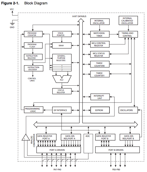
*Errata, often published prior to subsequent correction and relevant datasheet revisionATtiny is the smallest one in the 8-bit AVR family. It contains fewer pin, very cost efecttive for smaller scale project, but not ideal for project which hevily relies on peripheral connectivity, complex communication or counts on data storage.
Just like any other AVR MCU, these little fellas also brewed from Atmel's advanced RISC architecture.

Naming: 24/44/84 indicates 2KB/4KB/8KB of in system flash, which stores the bootloader and other program. ATtiny44 has 32*8 general purpose working registers, 4KB flash, and 256B EEPROM, much smaller than the ATmega328P which Arduino Uno used.
For the peripheral, it carries:
1* 8-bit & 1* 16-bit timer/counter, each with 2 PWM channel (very handy!)
10-bit ADC
A Watchdog timer & on-chip oscillator working @ 1MHz/8MHz
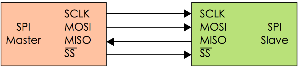
Programmable via SPI (the major protocol we will use during Fab Academy)For more info about SPI, you can checkout this link
Lastly, ATtiny44 runs on 0~20MHz clock @ 4.5 ~ 5.5 V, this is very crucial when hook up extra components, wrong reference voltage might cause dead circuit or even fries the MCU or components.


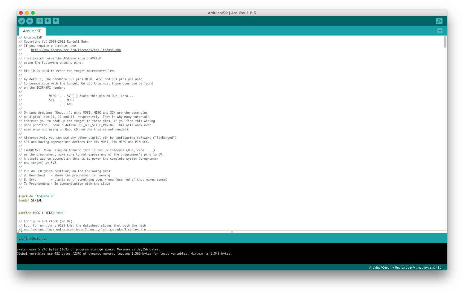
Cannot retrive device signature (got 0xc0, expected 0x00), googled the problem and seems like a common issue. Yet I had no clue for further examination.
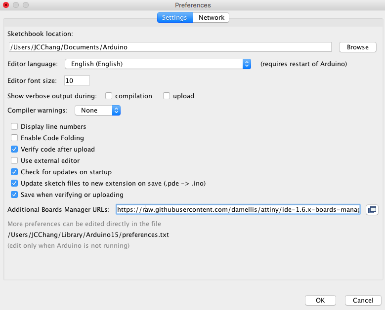
So I decided to move on to the Arduino route. Here are two useful article on how you can use Arduino as ISP and make Arduino IDE recognize your ATtiny as Arduino board.
Using the Arduino Uno to program ATTINY84-20PU by tsant
High Low Tech: Using Arduino as ISP
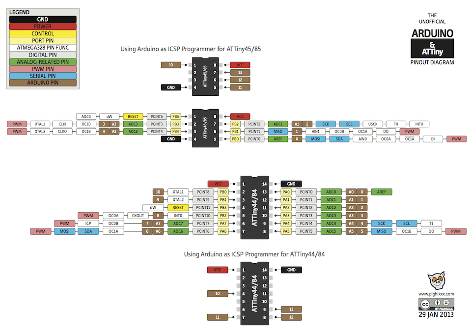
ATtiny - Arduino pinout map
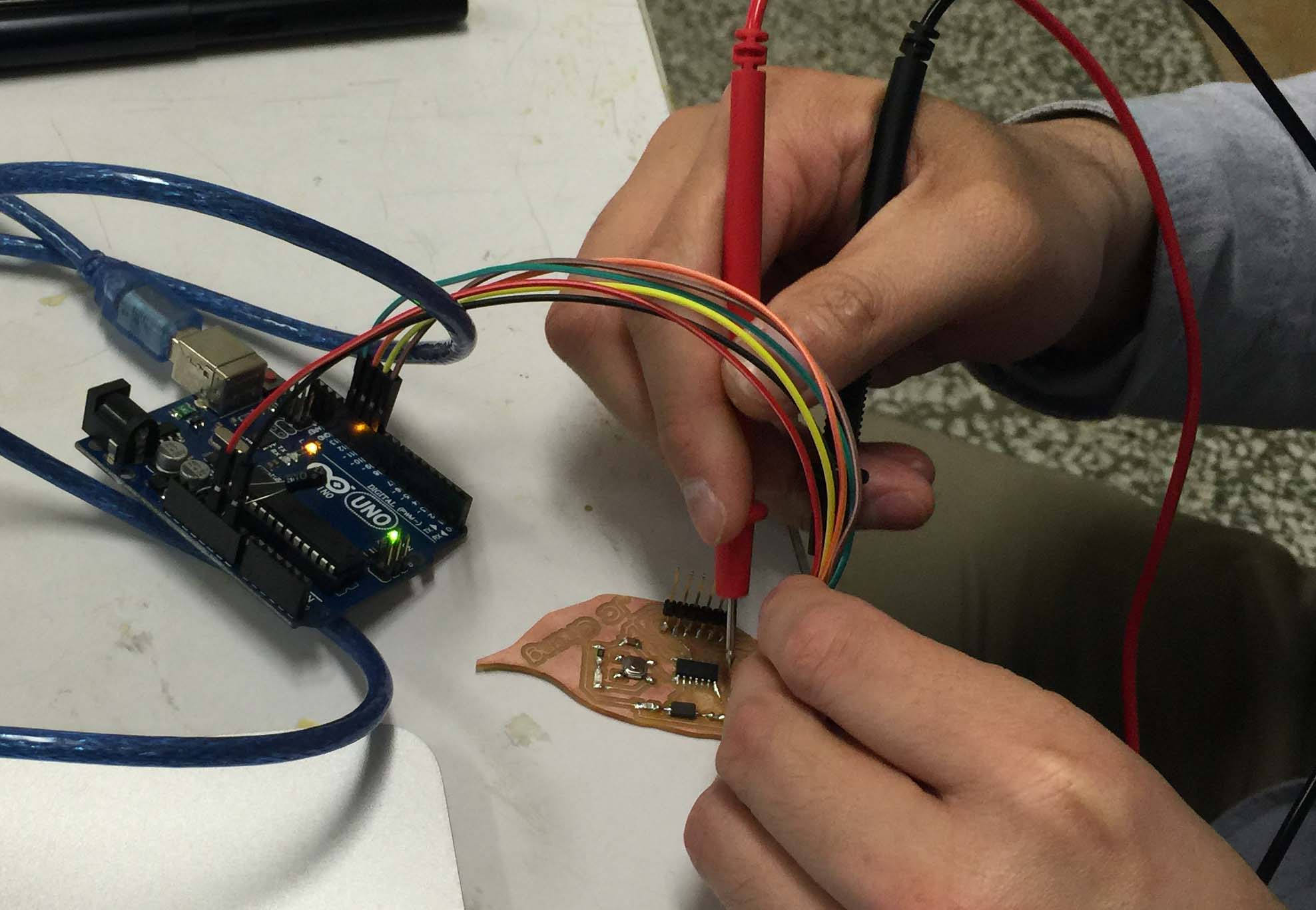
Wiring:
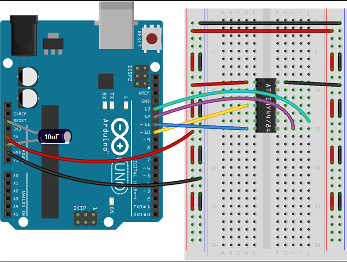
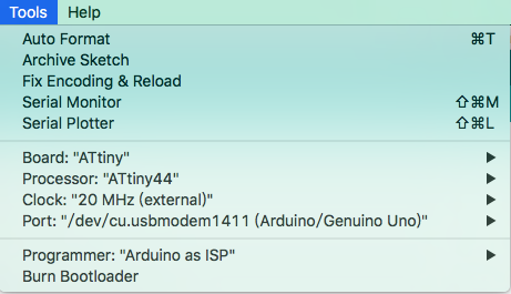
Yet, still got error codes from the Arduino IDE. It still read device signature unsolved while I tried to burn in bootloader to the ATtiny, which is actually burning fuse on the chip. So it led to faulty hardware or configuration issues.
Then the road of debugging begins,
 -CLEAR-
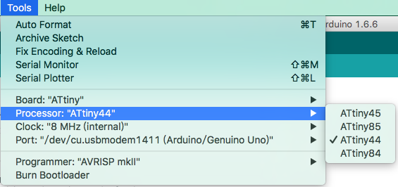
 Desoldered external crystal, and use internal 8 MHz instead, still did not work...
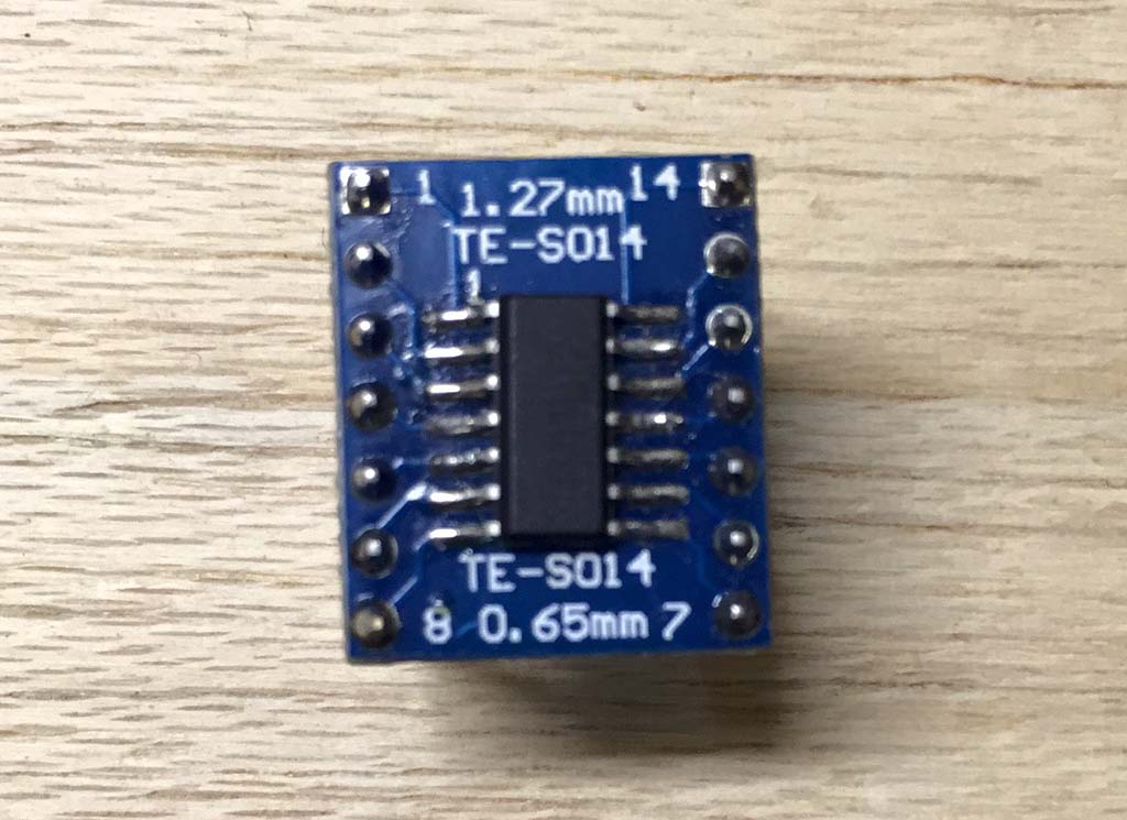
Out of desperation, I use a SO-14 pin coverter to connect the ATtiny solely
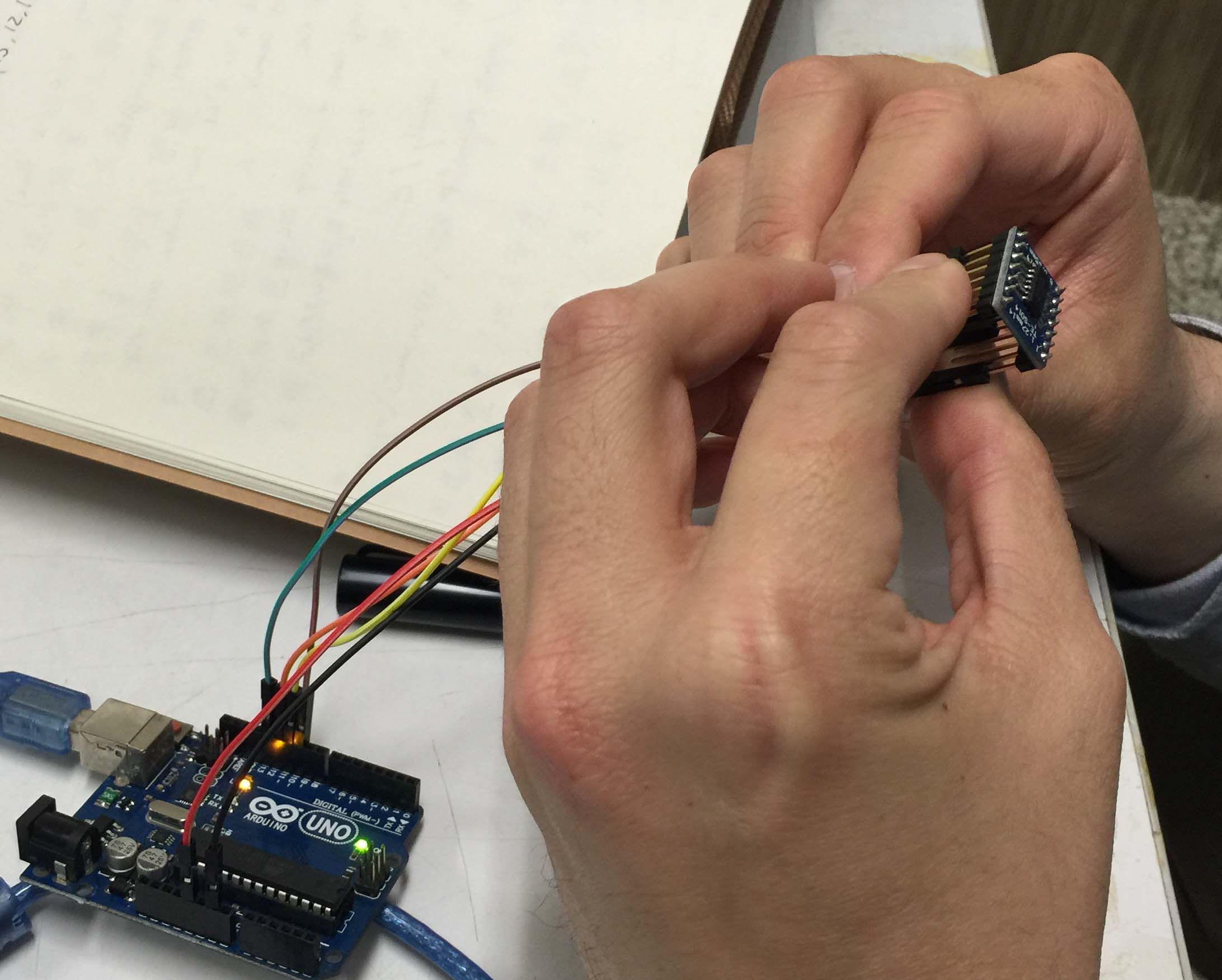
...and it worked!
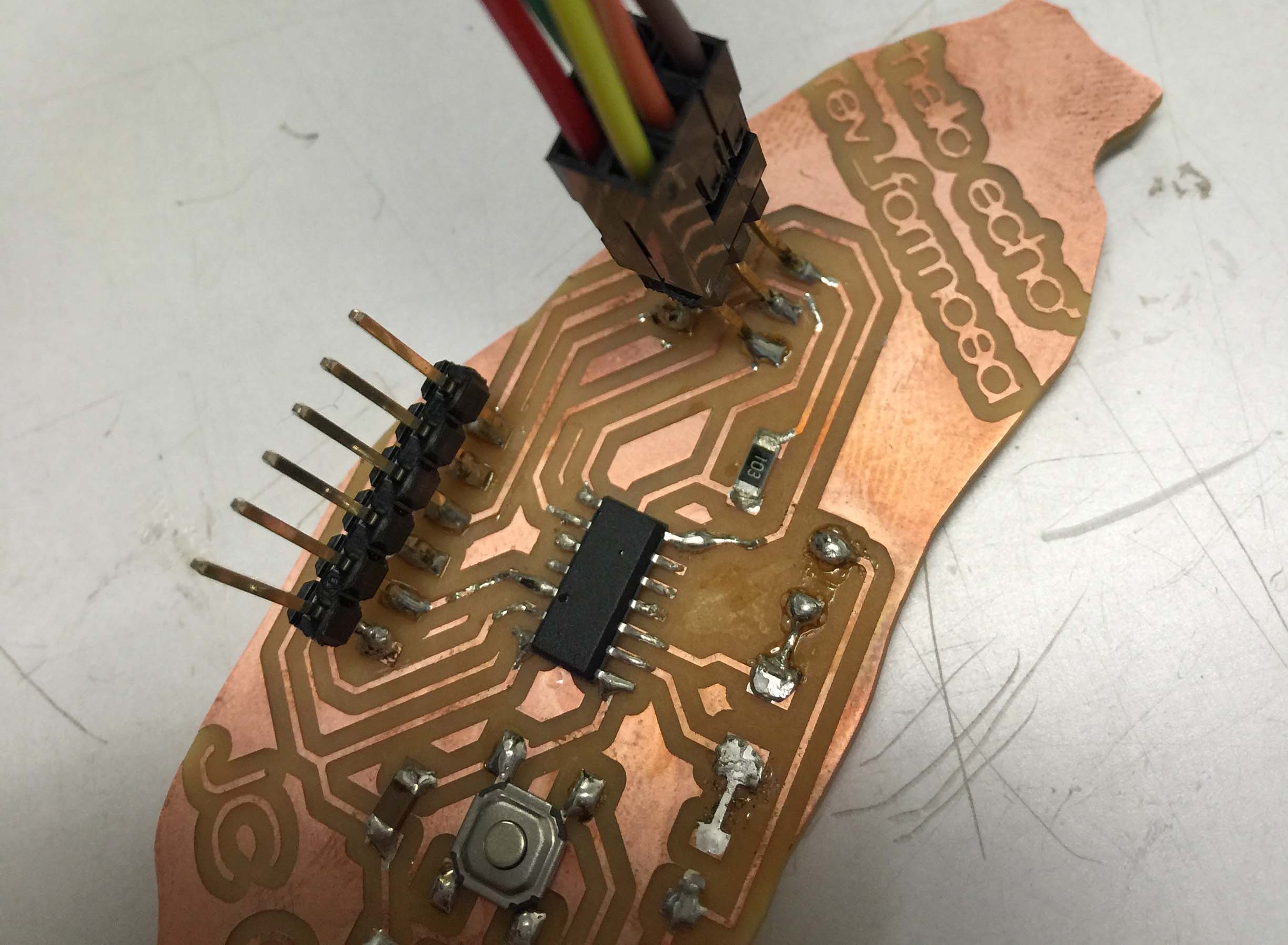
After 20+ hours of struggling, I finally realized I missed a point. That I did not connect PB3 on ATtiny44 to SPI pin header at all.

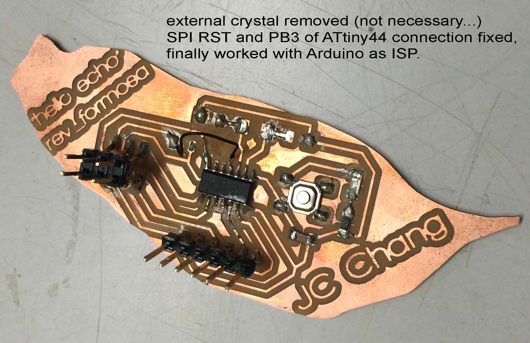
I followed this tutorial & hello.ftdi.44.echo.c & hello.ftdi.44.echo.c.make
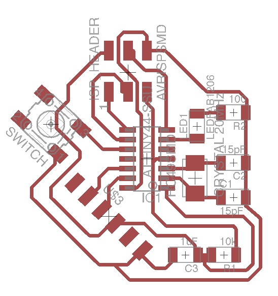
the "Hello Echo" sample code works, but I would like to rewire the design, and make the button and LED work as direct input / output to the ATtiny44.
-To be continued-
Update 3/30/16
This is the first revision with fully fuctional LED / switch, I will mill it and re-program the board if it works.
Update 4/02/16
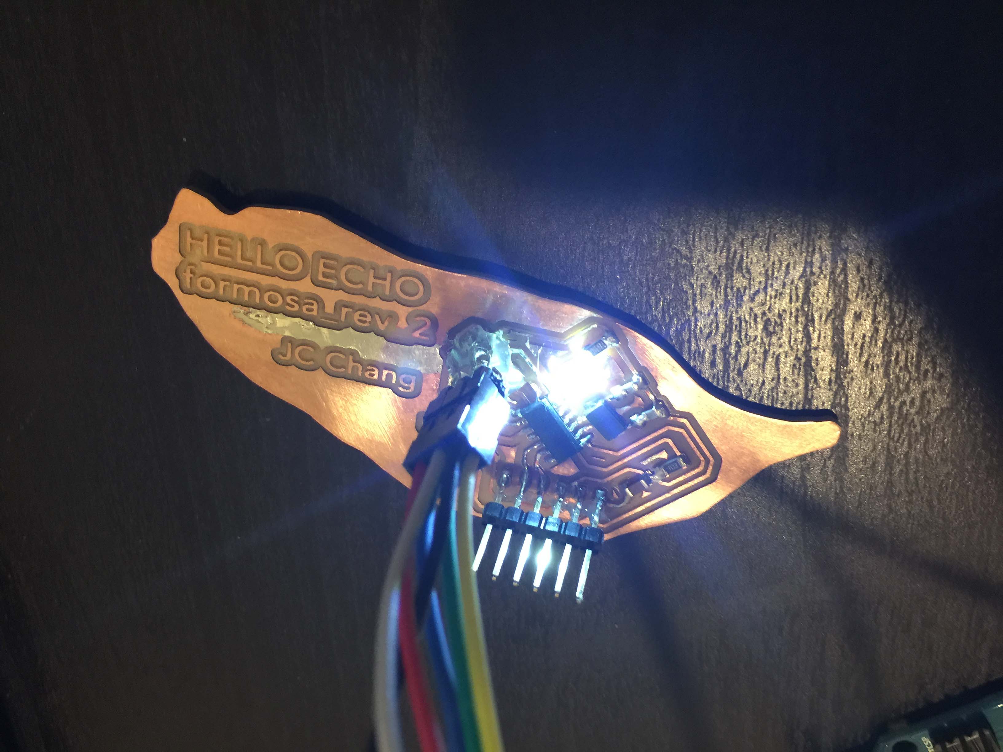
The revision worked well, I programmed a piece of Morse code into it, try translate it if you can :p
Code here: attiny_morse.ino