Input Devices
Let's build some sensing circuit.
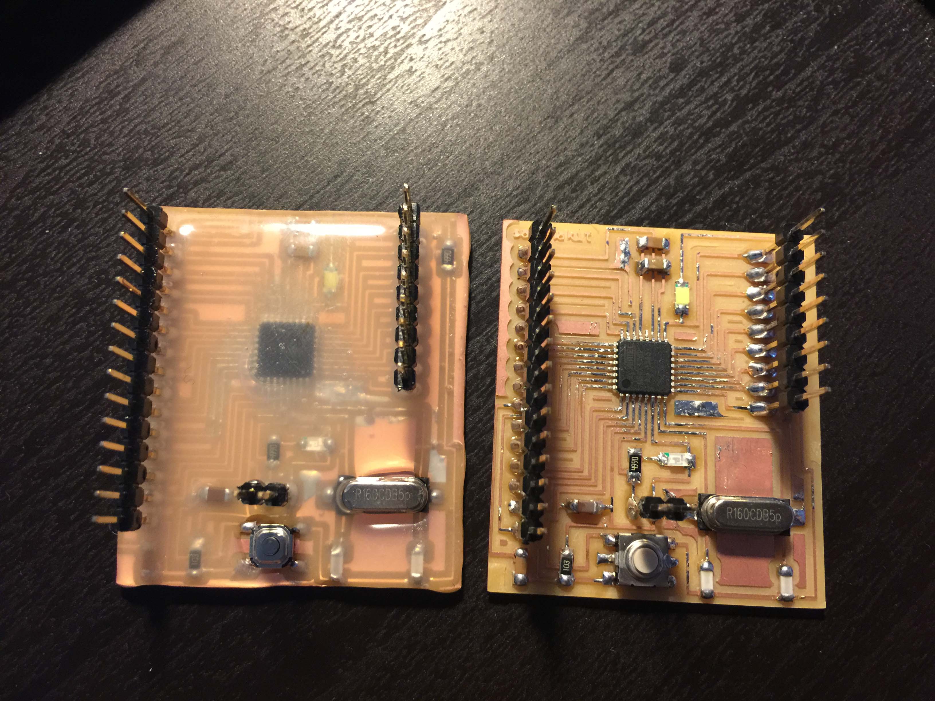
I made few Satshakits to hook up input devices, also I hope to utilize the design for following projects and the final.
Because the traces on Satshakit is very slim, I am afraid I would tear any of them when conducting test or assembling project. My solution is to use hot glue gun to apply an even layer of glue onto the board, then use hot air blower to re-melt the glue, it will become a layer of protection for your delicate board.
Before you do this, please make sure your circuit is properly soldered and has no bad joints. Else you might not be able to fix your circuit after the glue applied.
(updated 6/21/16)
Neil suggested the hot glue might have reaction with electronics. For now I did not really have that problem with the glue we have in Taiwan. But make sure you did conductive test before you apply this technique.
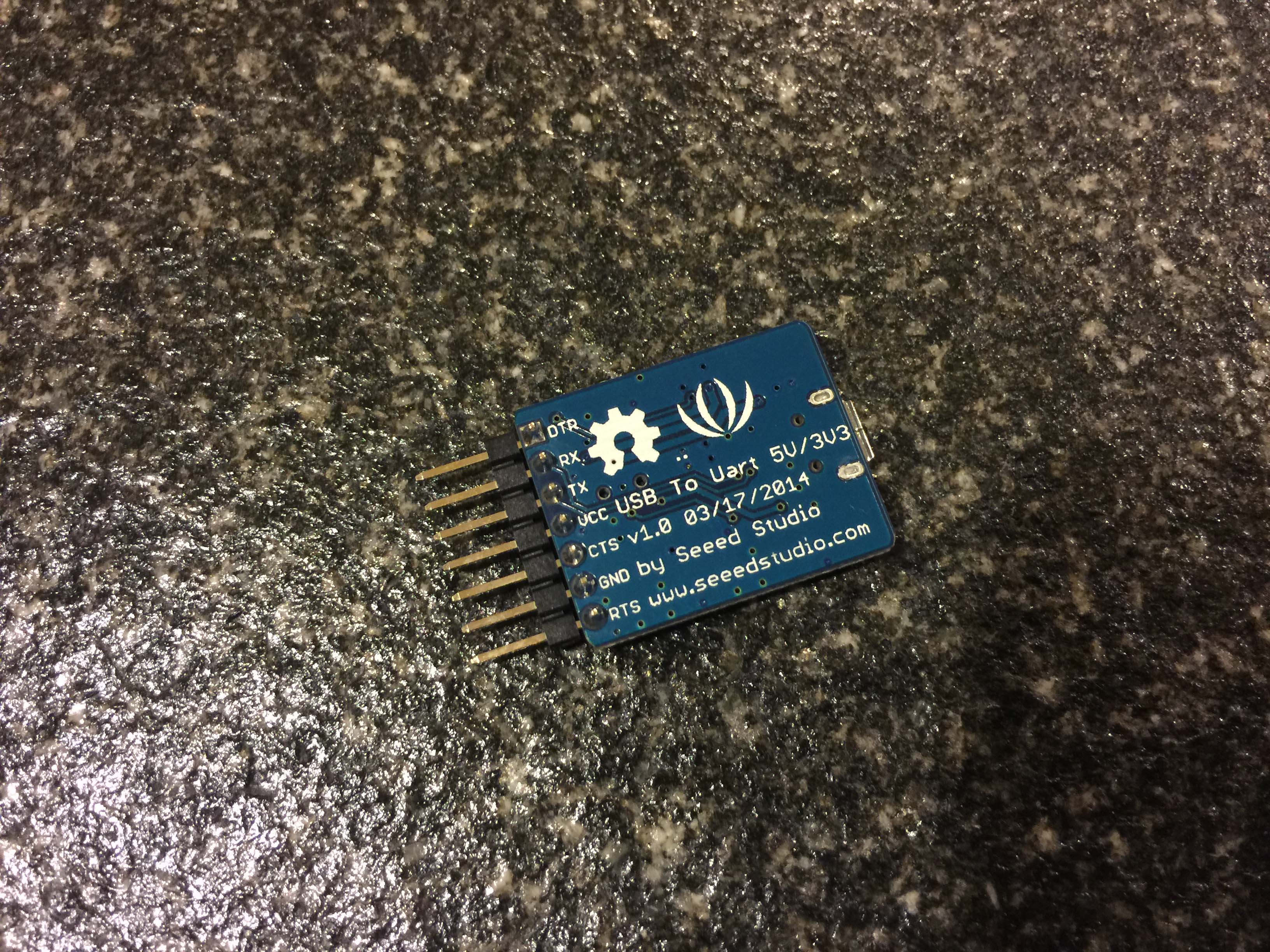
There are few ways you can program the board, I use a USB-UART module from Seeed Studio to do the job.


For the first exercise, I connect a vibration sensor from Seeed Studio to my Satshakit. The module is an analog-digital converter (ADC). It reads the vibration on a piezo membrane which generates tiny voltage changes when the membrane is compressed or squeezed.

image source: Wikipedia
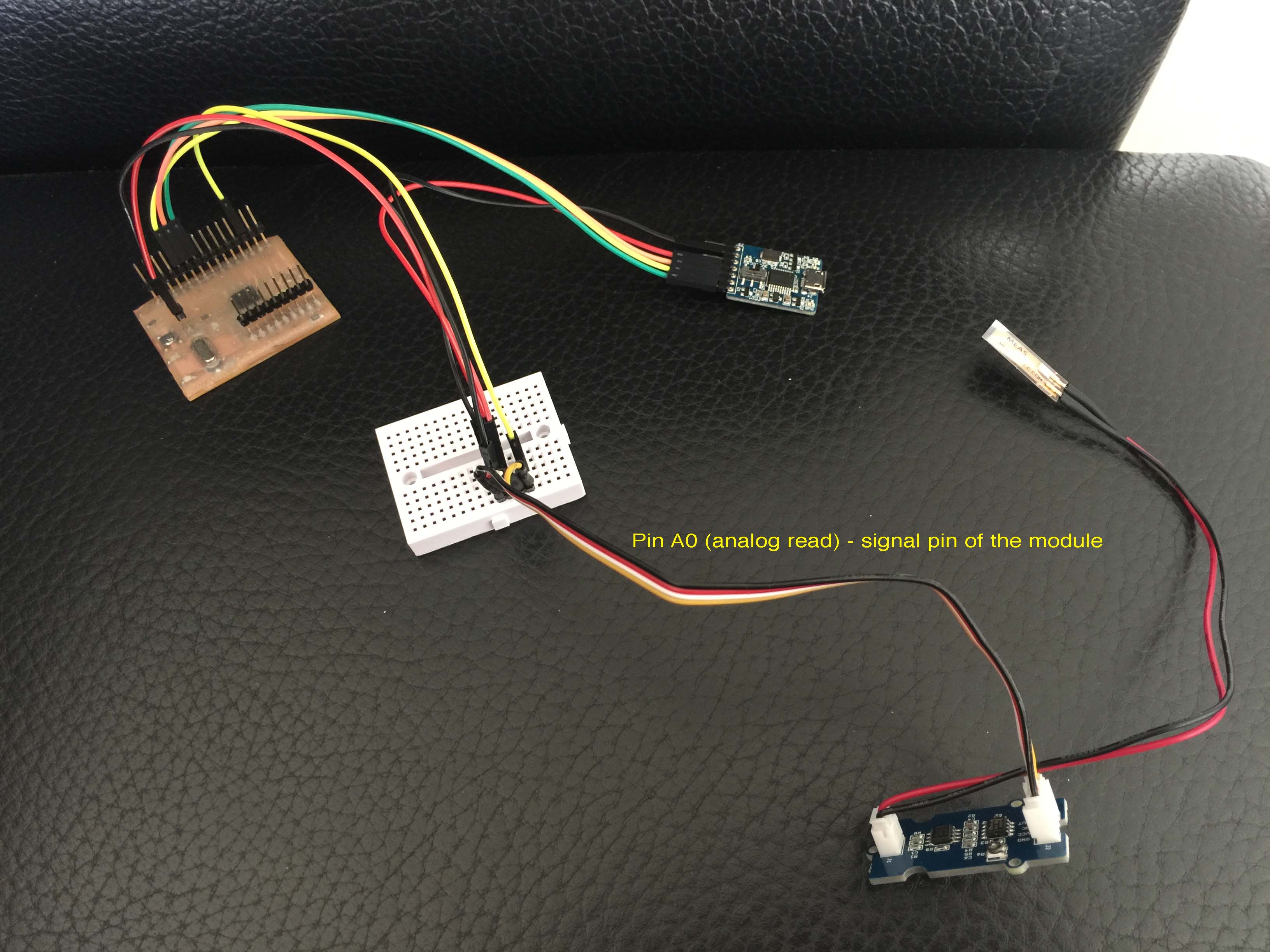
I wrote a very simple Arduino sketch, when the vibration reading is over the threshold, then the ATmega328 on the Satshakit will light the LED on pin 13.
Code here, you can also download the sketch directly
    const int ledPin=13;
    void setup() {
      Serial.begin(9600);
    pinMode(ledPin,OUTPUT);
    }

    void loop() {
    int sensorValue = analogRead(A0);
     Serial.println(sensorValue);
     delay(50);
     if(sensorValue==1023)
      {
        digitalWrite(ledPin,HIGH);
      }
     else
     {
      digitalWrite(ledPin,LOW);
      }
}Everything radiates infrared, a way to sense heat is using IR temperture sensor.
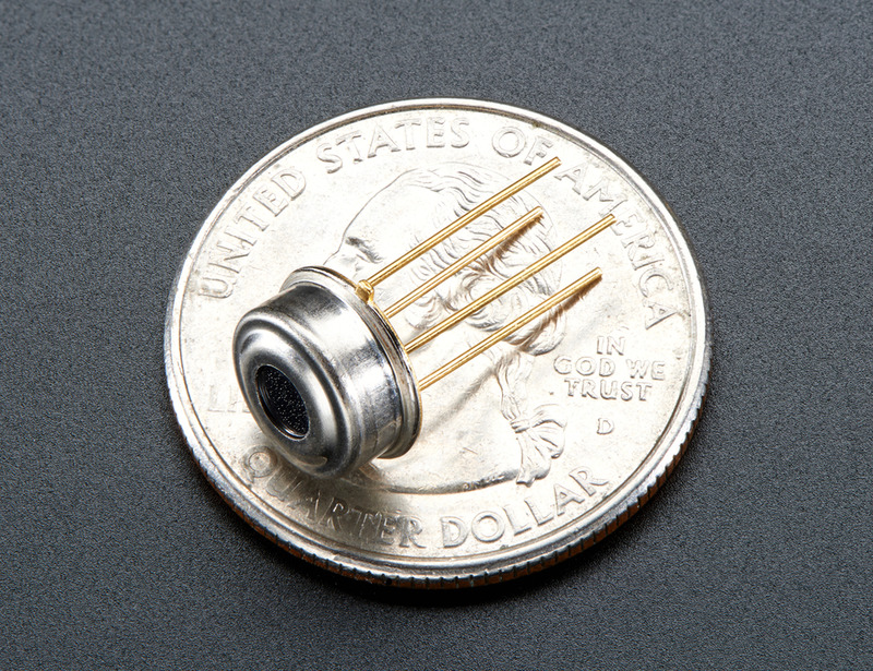
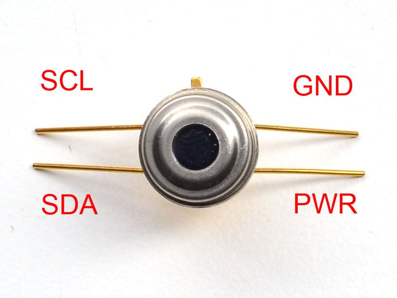
image: Adafruit
The sensor is very powerful one, has 3.3V / 5V version. The one I got from DigiKey is a 3.3V version.
Though many tutorial shows that I could actually just hook up the 3.3V version onto Arduino or other ATmega controller, I just don't think it is a good idea.
Since the IR thermometer, Melexis MLX90614 I bought from DigiKey is 3.3V version (by mistake...), thus I needed to support both 3.3V / 5V to the system at the same time.
For the first thing, I designed a power supply board with extra copper as heat sink for the entire system. I use 78M05 for 5V regulation, and 1117-3 for 3.3V.
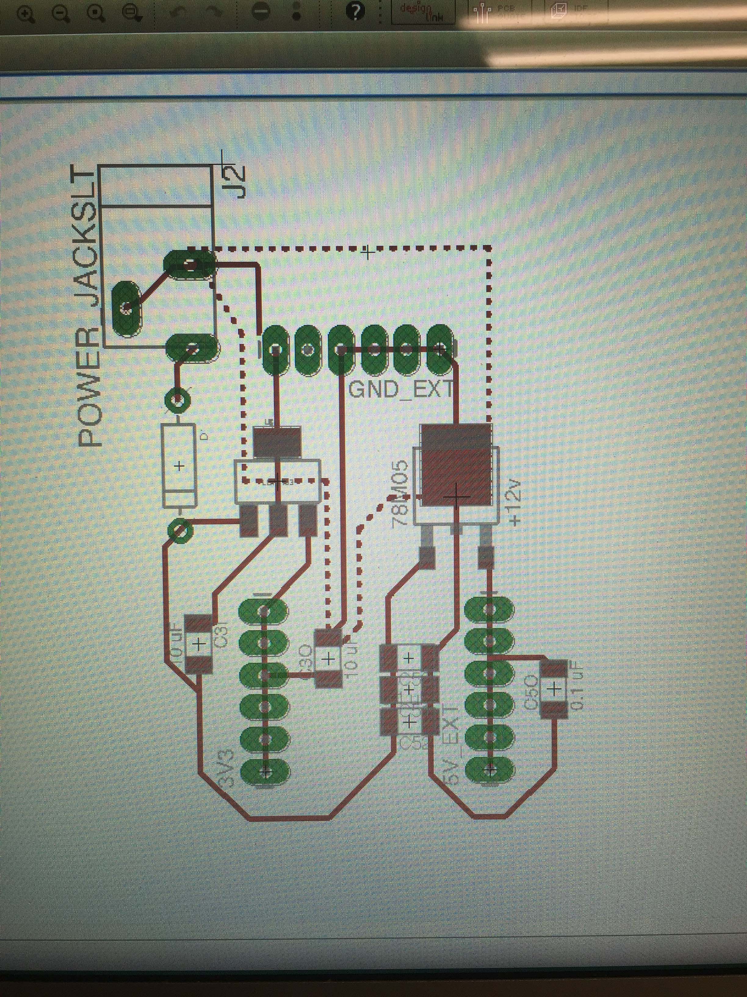
At first I burnt few 1117-3 and made some beautiful smoke and sparks. Then I realized the pin definition I got from the local supplier was actually wrong. It took me two days to settle the issue.
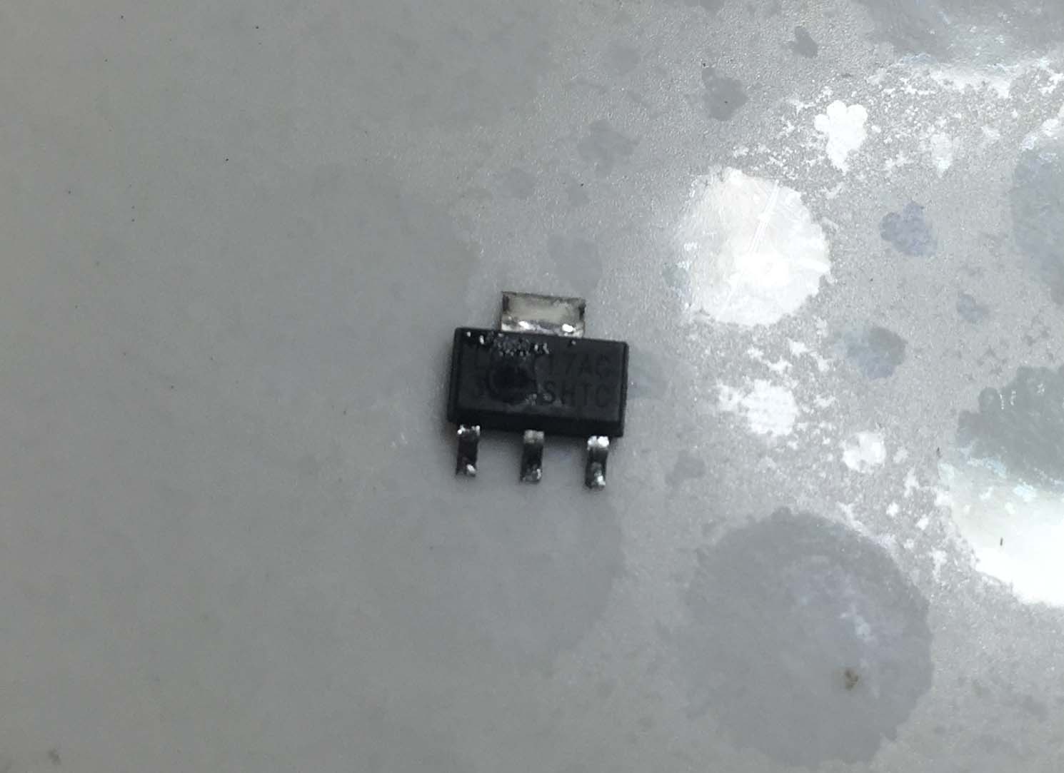
debugging...
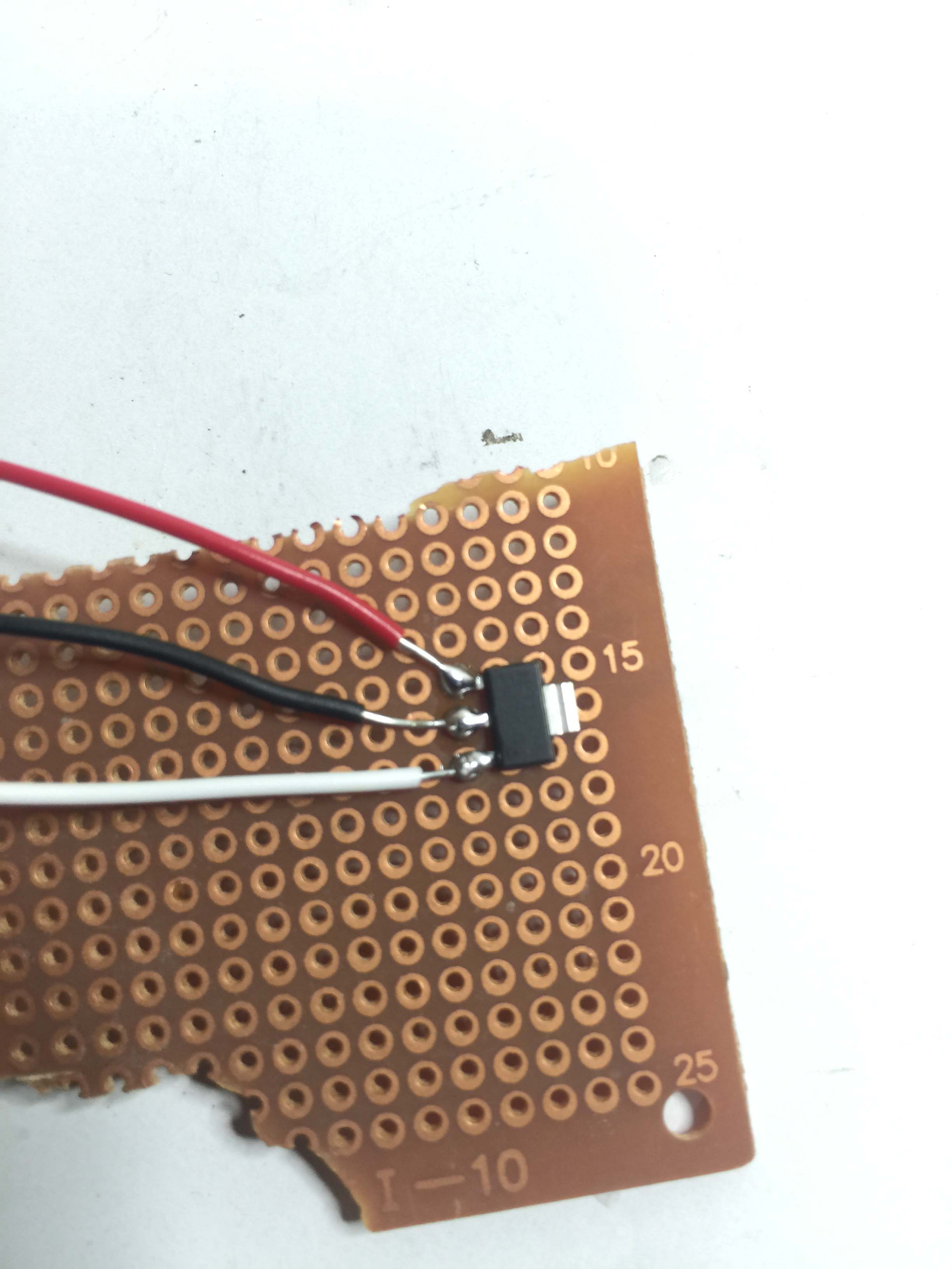
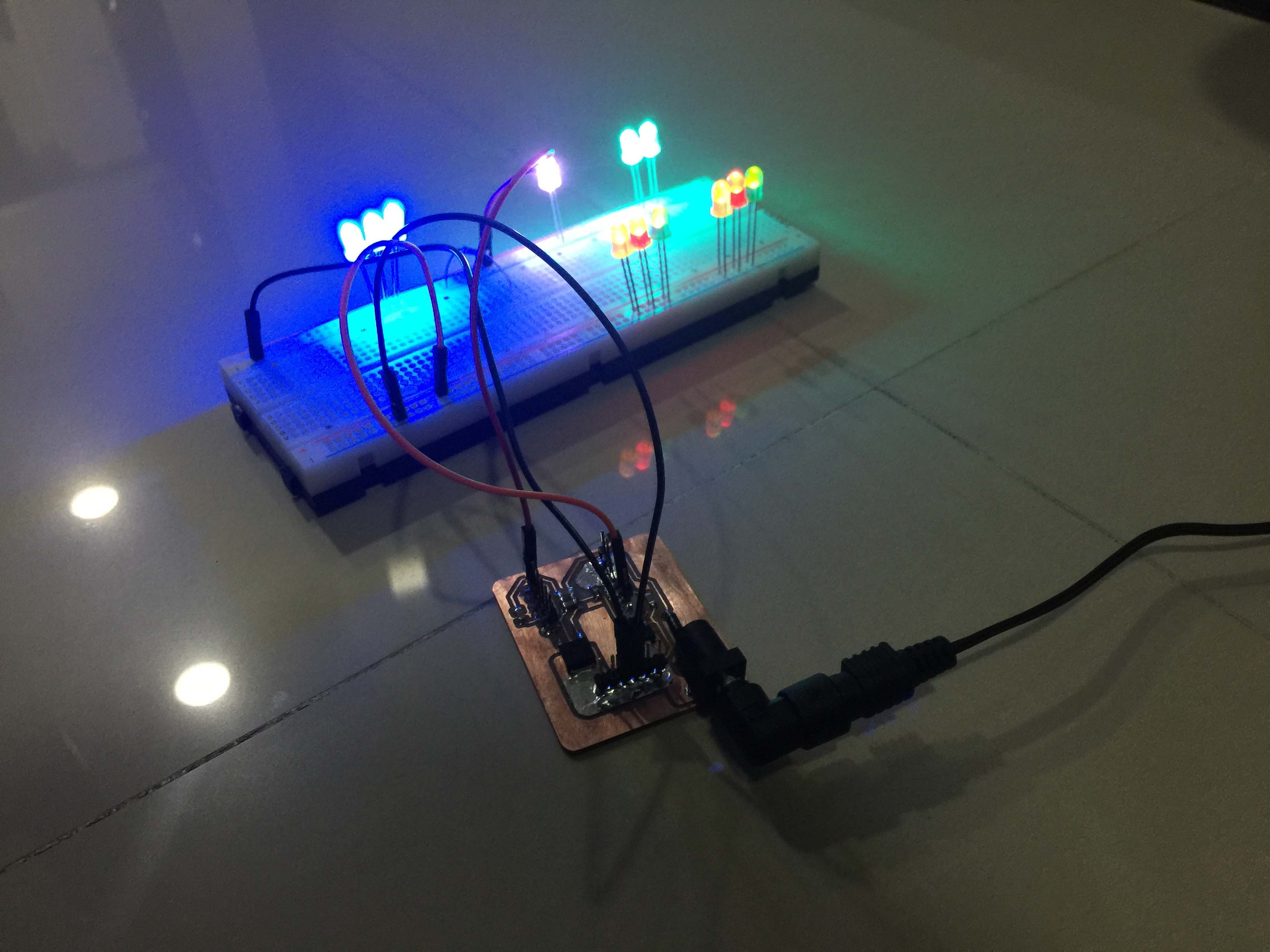
I used 12V/2A DC adaptor to support all the juices
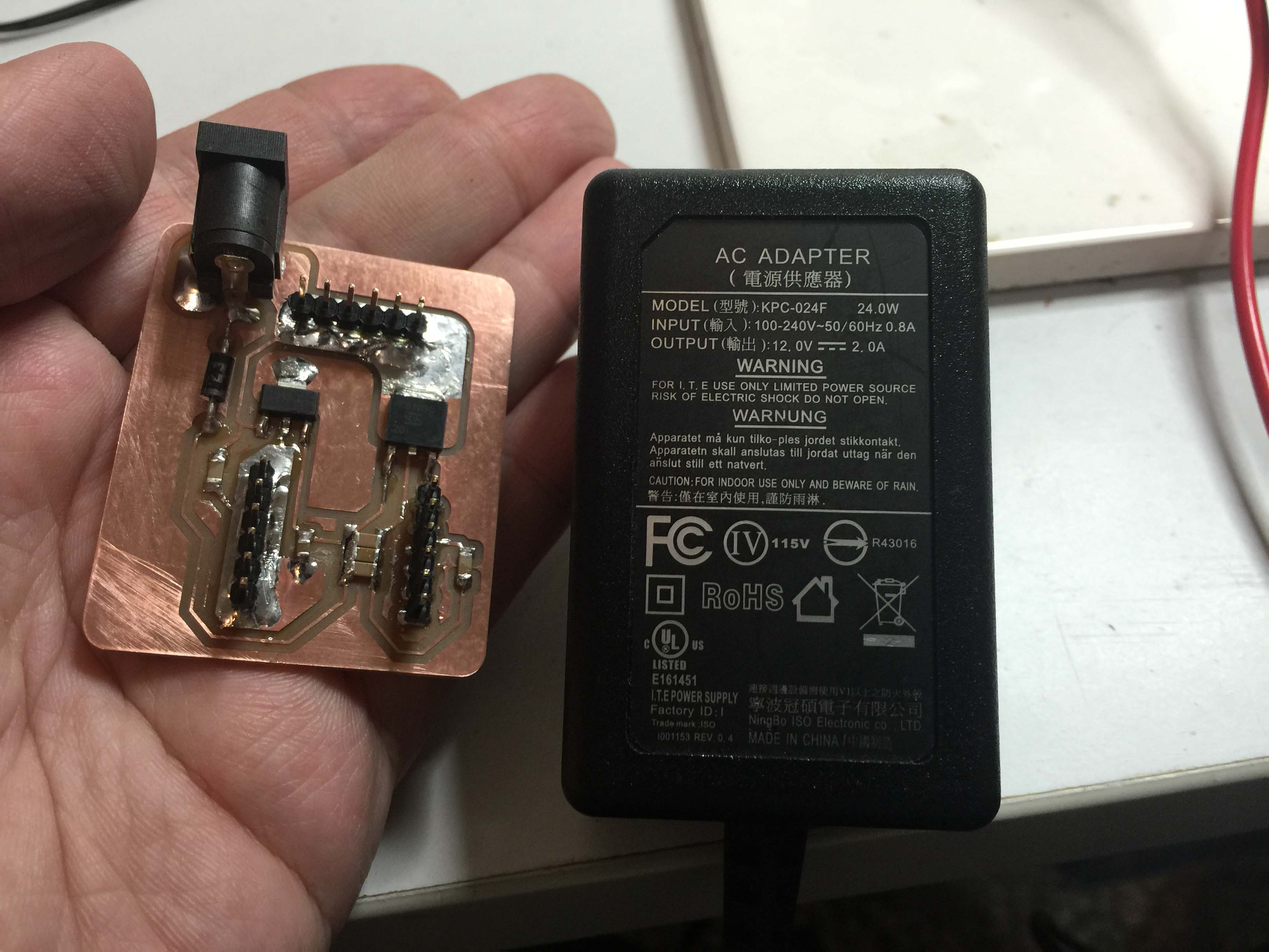
...and it worked like wonder! I am super satisfied with extra copper. It gave me sense of safety to my circuits.
The reason for not connecting 3.3V devices to 5V controller is, in a 5V digital system, when a signal reaches 5V, it is considered HIGH or 1. So when you connect 3.3V device to controller, it is actually LOW to it. In a long run it might damage the device or even the controller.
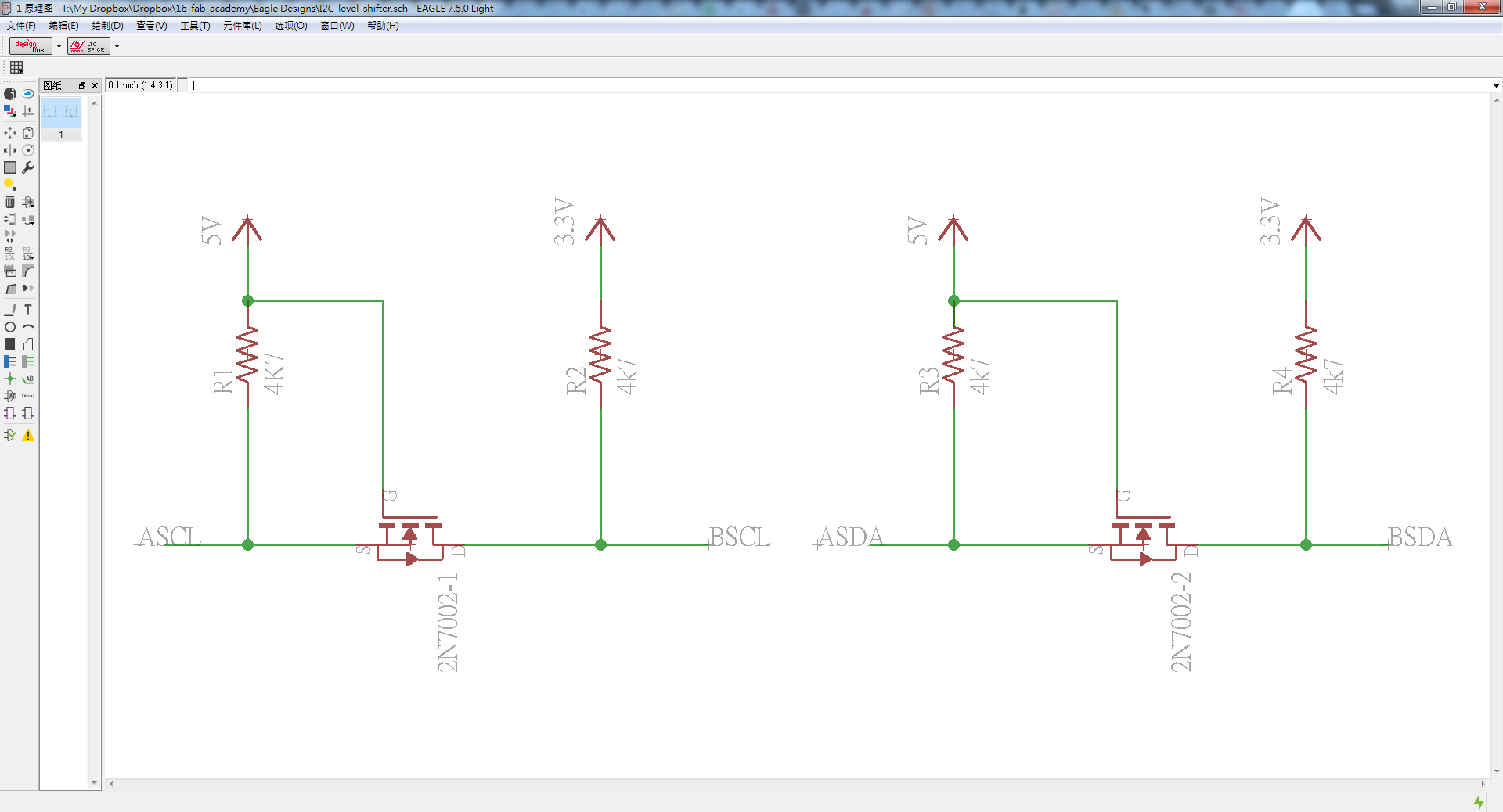
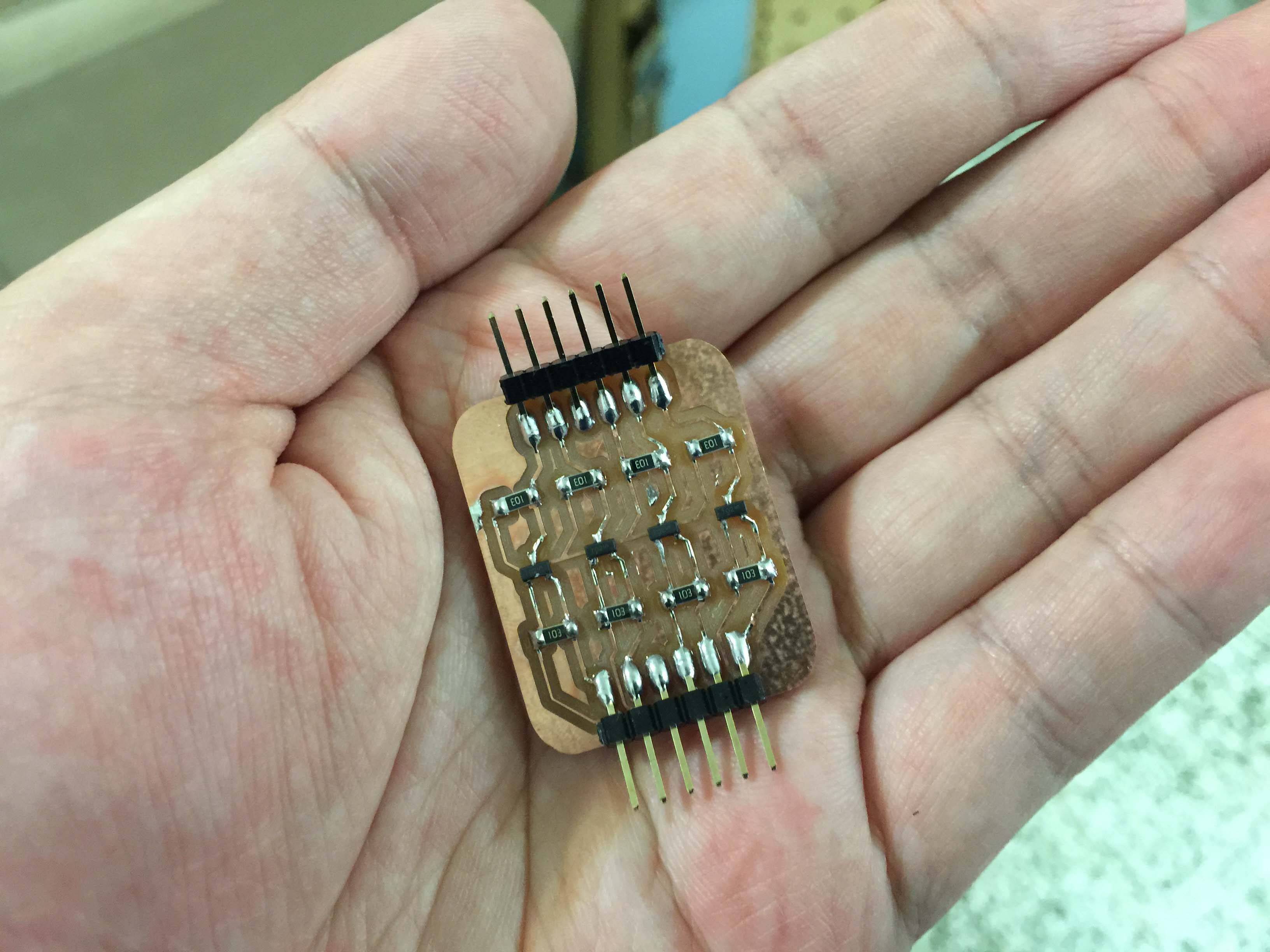
To safely connect the 3.3V sensor to 5V controller, I will use a level shifter.
The level shifter converts the voltage, "shifts" the voltage level from 3.3V to 5V, vice versa.
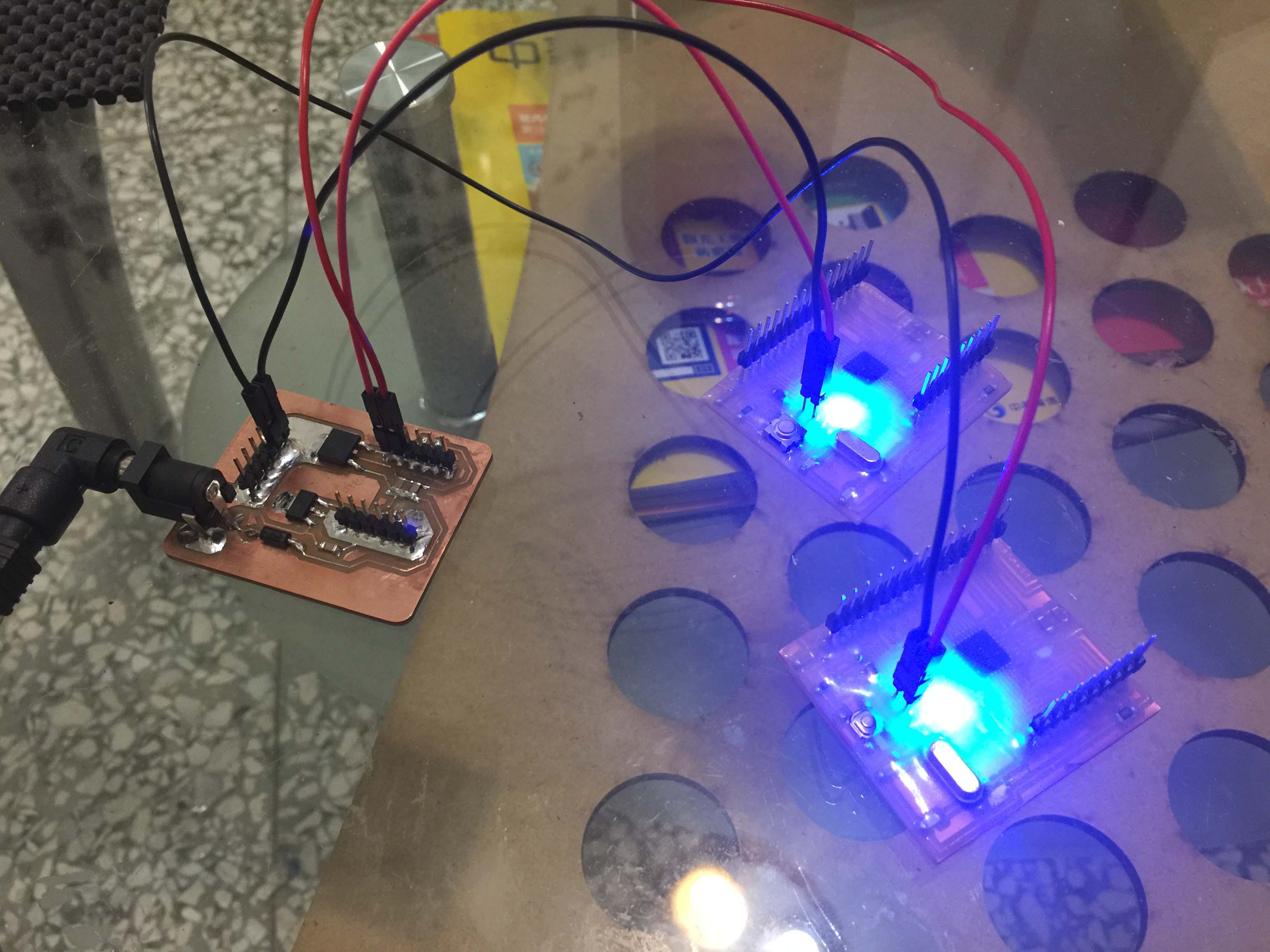
I named this fella "Fab Cookie", it looks just like one nice cracker with sesames doesn't it?
Testing
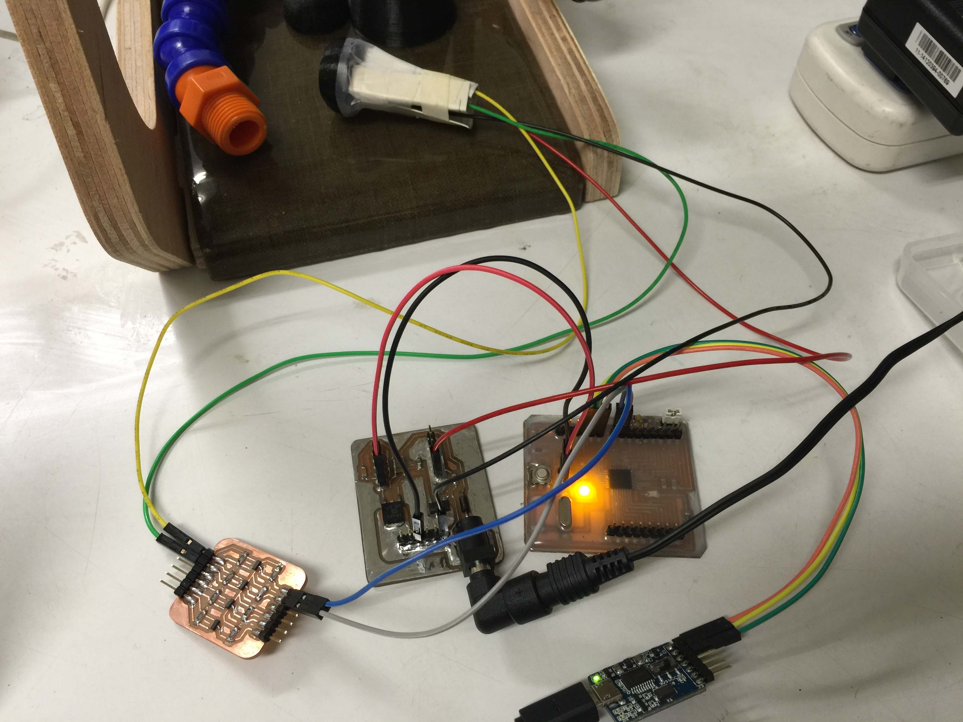
Everything was settled, but on my second smoke test, I killed the MLX90614 sensor. I think that could be caused by faulty ground plan of the circuits, so the 3.3V sensor was silenced by reverse current from 5V supply. Because the sensor is kind of expensive ($15 each), and I cannot find any local supplier with stocks. Did not want to risk my second and last MLX90614, I decided to go for plan b.
Plan b is rather simple, I designed a shield for Arduino Uno.
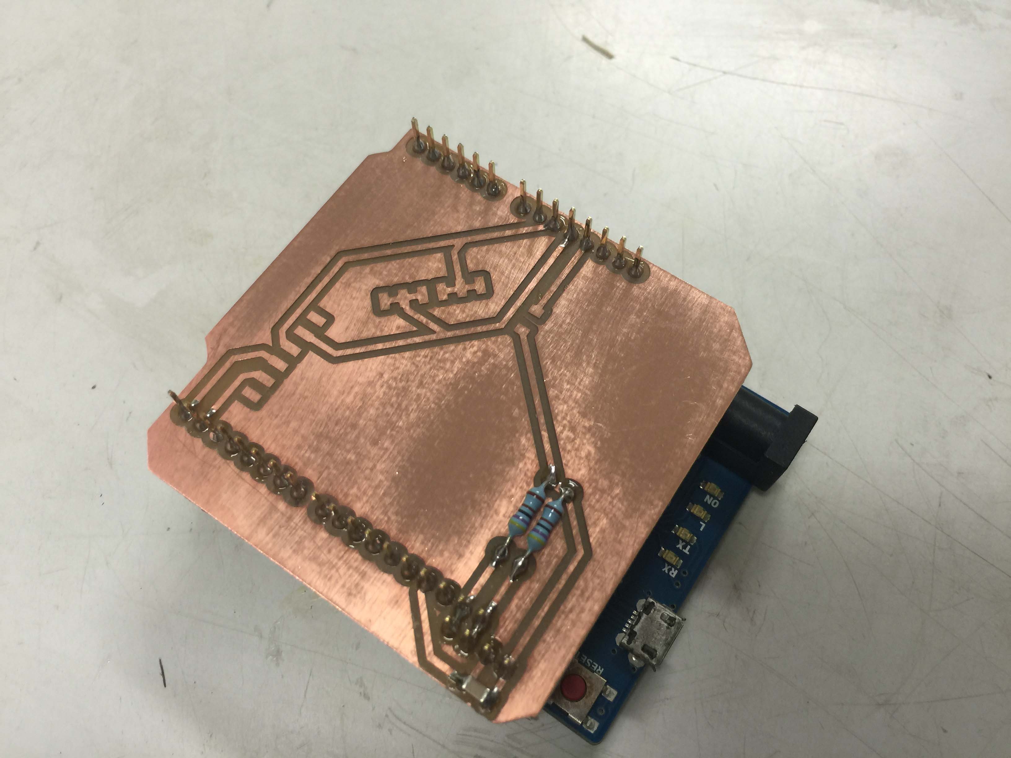
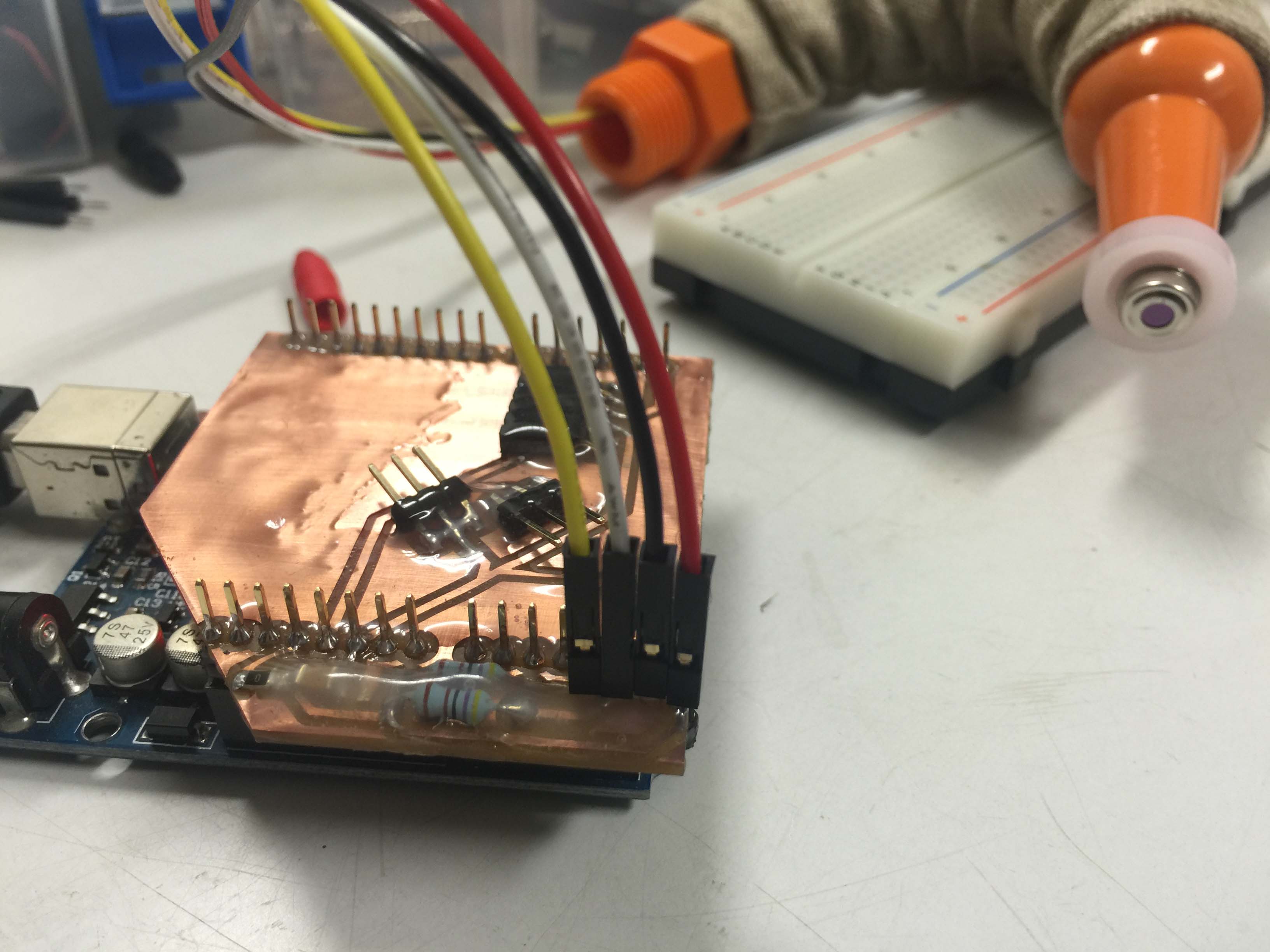
For supply and time constraint this is the fail-safe route I take for now. But I will try to design another board with proper ground plan and power supply.
Fab Cookie level shifter .brd .sch
12V to 5V/3V3 regualtor .brd .sch
"plan b" shield for Arduino Uno .brd .sch