Exercise 17 - Applications & Implications
Assignment
For this week's assignment, we have to propose a final project that integrates the range of units convered, answering the following questions:
- What will it do?
- Who's done what beforehand?
- What materials and components will be required?
- Where will the materials come from?
- How much will it cost?
- What parts and systems will be made?
- What processes will be used?
- What tasks need to be completed?
- What questions need to be answered?
- What is the schedule?
- How will it be evaluated?
What will it do?
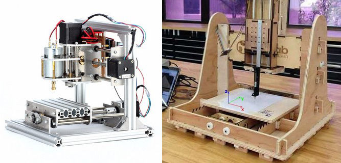
For my final project, I will be building a low-cost 3-axis CNC machine. The machine should be able to mill PCBs, acrylic, wood and aluminum. Some of my design goals for my final project are:
- Based on ATmega328/Arduino platform - easily fabricated in-house
- Low cost - use of aluminum profile, wood, 3D printed parts, which are readiliy available.
- Use free or open-source software for the CAM portion.
Who's done what beforehand?
DIY CNCs are very popular hobbyist projects. There are many sites on the Internet with information on building such machines, ranging from fully manual fabrication to 3D printed CNC. MIT's Centre for Bits and Atoms has a special group focussing on Machines that Make, with many project examples.
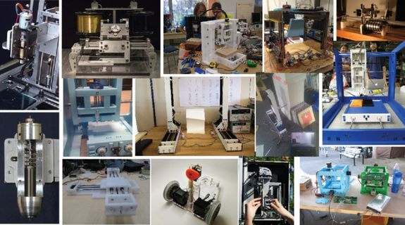
Even though many people and fablabs have built CNCs before, I believe that this is a very useful skill and knowledge for us here at Fablab SP. We are still relatively new to machine building and I would like to develop our in-house capability to build machines of any kind and this would be a first step in that direction.
Links to some popular sites with CNC builds:
Materials & Components
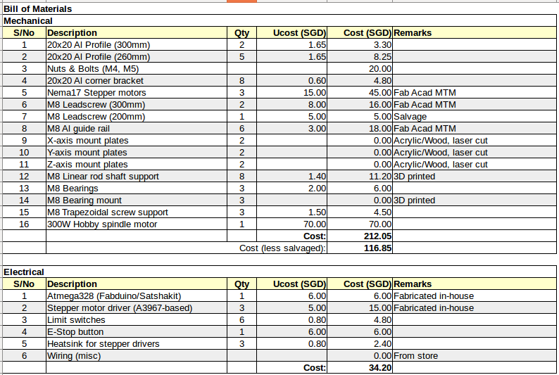
The bill of materials for my CNC build is shown below. I have split the BOM into mechanical and electrical parts. For the mechanical parts, I am using the stepper motors & leadscrews from our MTM kit. Purchasing the Nema17 stepper motors and leadscrews from China vendors will add another $80 to the overall cost.
For the electronics, I will be building an ATmega328-based arduino clone. I have drawn my own schematic & board layout for my arduino clone. Another alternative is to use Danielle's satshakit or the fabkit. For the stepper motor drivers, I have designed my own A3967-based stepper driver. An alternative to this is to use one of the stepper drivers designed by Ilan Moyer for the Fab-in-a-Box project.
What processes will be used?
For the CNC build, I've decided to start with 20x20 extruded aluminum frame. For the next revision, I will remake the machine in 12mm and 5mm plywood, in which case the frame will be milled. For the mount plates, I will be using either acrylic or 5mm plywood and a laser cutter to fabricate the pieces. The linear rod support pieces will be 3D printed and some of the labelling for the power supply box will be cut out using our Roland vinyl cutter.
For the electronics, I will be building an ATmega328 based controller and A3967-based stepper motor drivers. For initial testing of the mechanism, I will programming it in arduino sketch. For the final implementation, I will be using a customized gbrl implementation and g-code sender to transmit the gcode to my CNC.
One of the advantages of this implementation is that I can easily replace my custom-built electronics with a commercial arduino uno board with a gbrl-shield and polulu stepper motors. The complete system can be purchased online for USD11.50, inclusive of shipping.
What tasks need to be completed?
My CNC build can be divided into the following sections:
Mechanical:
- Frame structure: designed
- Linear rod support shaft: design completed, waiting to print
- Bearing mount: design completed, waiting to print
- X & Y-axis mount plates: designed, waiting to cut
- Z-axis mount plate: to do
Electrical
- ATmega328-controller: designed, to be milled, stuffed & tested
- Stepper motor driver board: designed, to be milled, stuffed & tested
Programming: I have separately tested each of the stepper motors individually using small test programs for each stage and also using a commercial gbrl-shield on an arduino, just to familiarise myself with arduino-gbrl CNC implementation.
What questions need to be answered?
Some of the questions that I have regarding my final project are:
- Design of the z-axis stage
- Accuracy and stability of the CNC, since this is actually my first CNC build
- Customising gbrl to use my own pin configurations, rather than those in a commercial gbrl-shield. This is not really a major issue, since I will be using jumper wires to make the connections, but it would be nice to have a design which is plug compatible with commercial designs
- Redesigning my CNC to use wood or acrylic instead of extruded aluminum profile, to give users a wider choice using materials available
- Redesigning the z-axis stage to accommodate different end-effectors
What is the schedule?
My planned schedule for the next 3 weeks is indicated below:
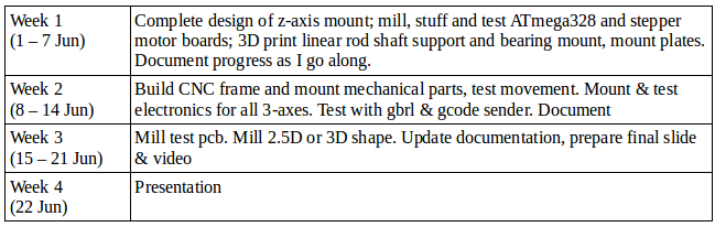
I have been working on the design for the mechanical parts of my CNC, evaluating and doing some of the electronics design and also concurrently testing gbrl and gbrl-shield with the stepper motors. The schedule looks quite tight, as some of the parts still need to be purchased, but fortunately, I already have most of the major parts I need, so baring equipment failure at our fablab, it should be doable.
How will it be evaluated?
The ultimate test for my CNC build would be to use it to successfully mill one of the pcbs which we have fabricated during our Fab Academy course, or to mill a simple 2.5D or 3D shape out of dense foam.
A partial success would be if the CNC is able to accept and follow a toolpath in gcode, either via a spindle motor or pen attached to the z-axis plate.