Exercise 08 - Embedded Programming
Assignment
For this week's assignment, we are supposed to:
- learn to read a microcontroller datasheet
- program the hello board to do something, with different programming languages and programming environments
Reading a Microcontroller Datasheet
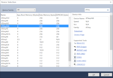
During the Electronics Design week, I modified Neil's hello.ftdi.44 board by adding a pushbutton switch and an led. Since this board is based on the ATtiny44 microcontroller, I started with the Atmel datasheet for this device.
The datasheet is available online from the Atmel site. There are many versions of the document, ranging from 196 to 286 pages. There is also a 26-page summary datasheet. The summary document contains the main features of the MCU, the pinout diagram, architecture overview, register summary, assembly instruction set and packaging information, but doesn't describe the microcontroller features in detail. To really understand the microcontroller, you would need to read the full datasheet.
- ATtiny44 datasheet - 238 pgs
- ATtiny44 summary document
- ATtiny44A datasheet - 286 pgs
- ATtiny44A datasheet summary

The information from the datasheet is very useful for learning about the microcontroller. For instance, we know that there are 3 versions of the MCU - the ATtiny24A, ATtiny44A and ATtiny84A, all with the same architecture and feature set, but with different amounts of flash memory. We also know that the MCU can retain its memory for 20 years at 85 degC and 100 years at 25 degC.
The datasheet also lists the peripherals available on this IC, such as timer/counters, pwm channels, ADCs, analog comparators and serial interfaces. We know that the IC is available in different packaging, ranging from 14-pin SOIC or PDIP to 20-pin VQFN. There are 12 programmable I/O lines on the MCU and it can operate with supply voltages from 1.8 - 5.5V, with operation at higher frequencies requiring higher supply voltages. If I'm design a part for use in space, where temperatures fall to 0 Kelvin (-273 degC), I wouldn't use this part because it is only rated for temperatures between -40 to 85 degC.
Detailed Description of ATtiny44A
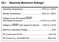
The detailed datasheet contains a lot of very useful information about the microcontroller. We know that Port B (PB0:3) and Port A (PA0:7) are bit programmable, bi-directional I/O ports with internal pull-up resistors. PB3 can be used as an I/O pin instead of RESET and this is done by programming a 0 into the RSTDISBL fuse. We also know that the port pins are tri-stated when the MCU undergoes a reset. From the Electrical Characteristics section, we know that each I/O pin can source or sink a max of 40 mA.
The I/O Ports section tells us that each port pin consists of 3 register bits: DDxn, PORTxn and PINxn. DDxn selects the direction of the corresponding pin, where a logic 1 in DDxn configures Pxn as output and a logic 0 configures it as an input pin. We also know that to activate the internal pull-up resistor if Pxn is configured as an input pin, we need to write a logic 1 to PORTxn. To disable the internal pull-up resistor, we can either write a logic 0 to PORTxn or configure the pin as an output pin.
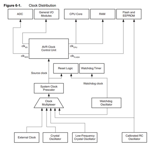
The Clock System section of the datasheet tells us that the ATtiny44A can derive its system clock from different sources: internal RC oscillator, low-frequency crystal oscillator, crystal oscillator or external clock source. The clock signal passes through a clock multiplexer circuit and from there, to a prescaler unit. There is also a watchdog oscillator, which is used to reset the MCU if the watchdog timer is not reset with the WDR instruction within a prescribed time interval. The watchdog timer is initially disabled, but can be enabled by writing a logic 1 to the WDE bit in the WDTCSR (Watchdog Timer Control and Status Register).
The clock source is selected by means of the CKSEL[3:0] bits and the Start-up Times with the SUT[1:0] bits. The prescaler value is configured via the Clock Prescaler Select Bits (CLKPS[3:0]). For example, to configure the MCU to use the 8 MHz internal RC oscillator, with a prescaler value of 8 (i.e. divide by 8, for a 1 MHz clock), start-up clock 14CK + 64 ms, the settings would be:
- CKSEL[3:0] = 0010
- SUT[1:0] = 10
- CLKPS[3:0] = 0011
There are a lot more settings and configuration examples in the ATtiny44A datasheet and it is meant to be used as a reference when you need to access specific features of the IC.
XMega-16E5
I also decided to take a look at the xmega datasheet, to try understand why Neil is so excited about this AVR family. According to the Atmel website, the Xmega microcontrollers offer real-time performance, high integration and ultra-low power operation.
A look at the ATXmega datasheet shows that the Xmega family devices have built-in DMA controller, crypto engine, 12-bit ADCs and DACs. They operate with supply voltages from 1.6 - 3.6V and clock frequencies up to 32 MHz. The family also supports a new event system, where events are queued for processing, reducing the need for interrupts.
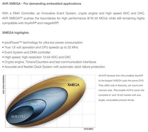
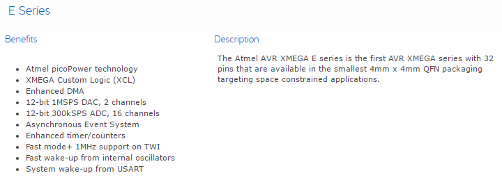
There are currently 5 series in the ATXmega family. These are the A-Series, B-Series, C-Series, D-Series and E-Series. Each series is targetted for a specific range of applications, with a common set of peripherals in the series family, but different amounts of memory. I've included the general description of the A & E-series as an example.

Since all the microcontrollers in the same series share the same set of peripherals/feature set, the documentation is also archived differently. Each series has a series manual (e.g. XMEGA-E_Manual) and a datasheet specific to that particular IC (e.g. ATxmega16E5_datasheet).

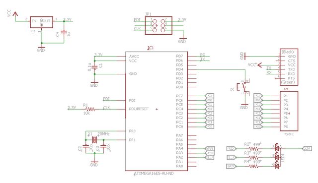
Reading the Xmega16E5 datasheet, I realized that the microcontroller is available in many different packages and that the version I needed was the ATxmega16E5-AU, which is the 32-pin TQFP packaging. The datasheet also gives us the pinout for the package. This is also important, as the Eagle fab.lbr does not contain the part for the xmega16E5. Using the information from the datasheet, I created the Eagle symbol and package for the part, after which I could use it to design my Xmega16E5 hello board.
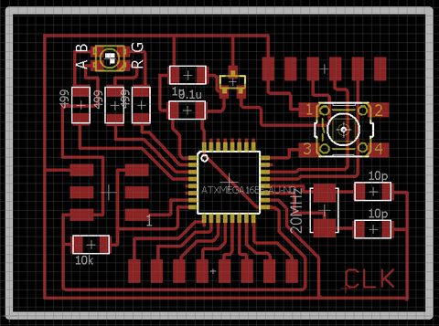
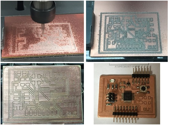
With my design done, I proceeded to mill and stuff my Xmega16E5 Hello board, as I wanted to explore this new microcontroller, in addition to the ATiny44 Hello board.
Programming: ATtiny44 Hello Board (Arduino IDE)
I work on 3 different hardware platforms: Linux, OSX and Windows, so I wanted to try writing code for the Hello Board on all 3 platforms. First up was using the Arduino IDE, which can be downloaded from Arduino.cc. The Arduino IDE is available for Windows, Linux and OSX, which is great! I have used the Arduino IDE before, from the ver 0.22 onwards.
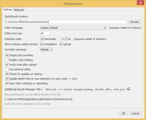
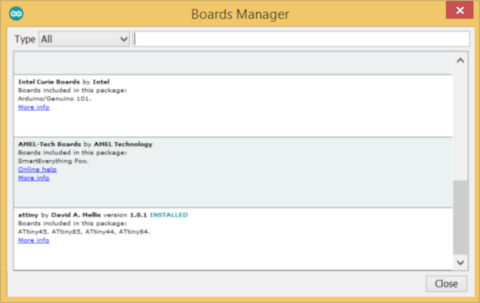
After downloading and installing arduino ver 1.6.7, the first thing that I needed to do was to install support for the ATtiny processors. David Mellis and his team at high-low tech has written a very nice tutorial on how this can be done. The procedure for Arduino 1.6.x is very different from that for Arduino 1.0.x. You basically add in the URL for the ATtiny support in the "Additional Boards Manager URLs" in File > Preferences, then go to "Boards Manager...", scroll down to look for the URL for ATtiny and install it.
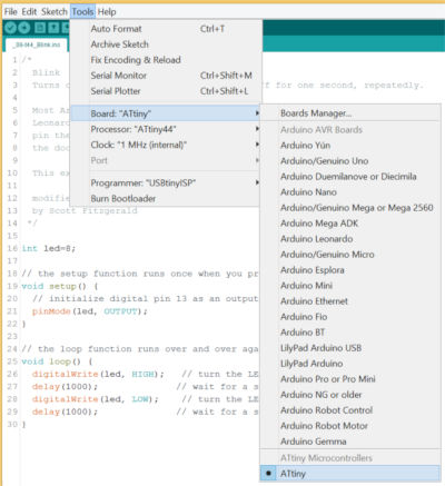
Once that is done, the Arduino IDE will now support the ATtiny range of processors (ATtiny45/85 and ATtiny44/84). For my hello.ftdi.44 board, I selected ATtiny44 as the CPU and the internal 1 MHz clock as a start. I prefer to test my board using the internal clock initially, so that I can verify if the board and I/O works. That way, once I program the CPU to use the external crystal or resonator, if it doesn't work, I know that it is related to the external oscillator circuit.
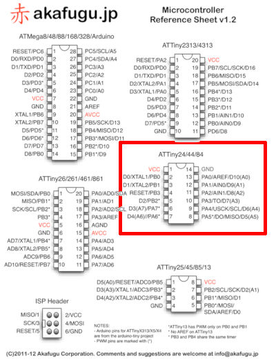
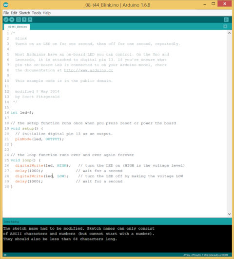
The first program that I did for my Hello Board was to blink the on-board LED. To do this, I opened the Blink example sketch that came with Arduino IDE and modified the code, using a modified pin definition. For my hello.ftdi.44 board, the LED was connected to PB2, which is pin D2 according to akafugu.jp.
Issues/Problems
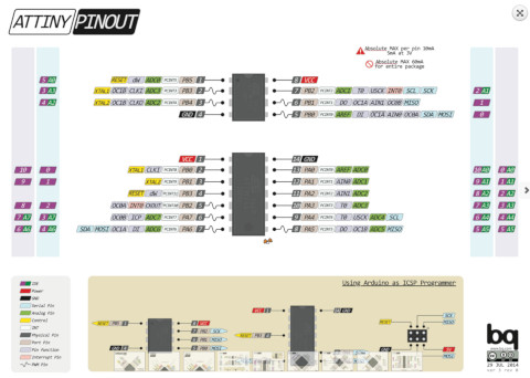
After compiling and uploading my sketch to the hello board, the LED failed to blink. Checking connectivity with a multimeter, everything seemed OK, but the LED just didn't blink. Pulling the LED low with a jumper wire turned it on, so there was nothing wrong with my wiring. I tried changing the pin definition for my led variable to PB2, but this didn't seem to work either. After a bit of googling, I found a site (pighixxx.com) that referenced PB2 on the ATtiny44 as D8. I changed the led variable to 8, compiled and uploaded the program to the hello board again and elation! The LED on my hello board blinked at last. What I discovered is that Arduino 1.6.x changed the pin definitions on the ATtiny parts, compared to Arduino 1.0. The way that additional CPUs (variants) are added to the IDE is also different. One of the things that I did when my lED did not blink was to look for the portpins.h file, but could not find it at all. My final program code is shown below.
The next task was to write a simple program to test the pushbutton operation. The easiest was to turn the LED on or off based on the status of the pushbutton. The following code achieves that:
    void loop(){
        digitalWrite(led, digitalRead(pb));
    }
Surprisingly, my simple program did not work. Pressing the pushbutton had no effect on the state of the LED. A continuity check did not reveal any errors with the pushbutton part of the circuit. I started measuring the voltages and resistance values for the pushbutton circuit. That was when I found out that my 10k pull-up resistor had a reading of 500 kOhm. The solder connection looked OK, but it was a cold solder joint. After resolding the connection, the program worked perfectly.
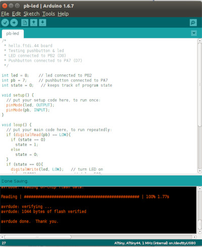
Rather than using the pushbutton as a simple on/off switch, I decided to write a program where a button press will change the mode of flashing of the LED. The figure below shows a partial code segment and the video shows the program in operation.
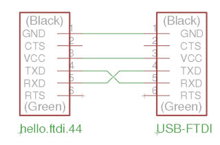
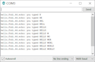
Since Neil's Hello Board talked to a computer via the ftdi interface, I wanted to see if Arduino IDE's software serial library could handle the task at 9600 baud. On the FTDI interface, pin 4 is defined as TX and pin 5 as RX. On my hello.ftdi.44 board, this means that TX (PA0) should be connected to my USB-FTDI RX and RX (PA0) on the hello board connected to my hello.ftdi.44 TX pin (see figure below).
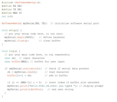
Since the function of PA0 and PA1 are configured via software, it is just a simpple matter to configure PA0 as the RX pin and PA1 as the TX pin, thereby avoiding swapping the cable connection. My echo program code is shown below and the output of the program when the message "HELLO WORLD!" is typed is shown in the following figure.
Using Arduino IDE on my Ubuntu PC is essentially the same, except that I have to start the program with the sudo command, in order to avoid getting a "Permission Denied" error. To fix this problem, I need to add my user account to the dialout group, log out then log back in again. This is done using the command below.
sudo usermod -aG dialout <user>
I also tried programming my hello board on my MacBook, running OSX El Capitan. Arduino IDE had difficulties recognising my fabISP programmer. I tried using my USBasp programmer instead. Same problem. OSX El Capitan just refused to recognise any of my programmers. I decided to try both my genuine Arduino Uno R3 and Duemilanove boards - Arduino IDE still refused to recognise both boards. The issue was not the Arduino IDE, as OSX did not recognise any of the boards I plugged in at the OS level.
A bit of googling revealed that many other MacBook users encountered the same problem after upgrading to El Capitan. Apple introduced a new security feature in El Capitan - Security Integrity Protection or SIP. With this feature enabled, OSX will not allow any usb or serial device that has not been approved by Apple to connect to the MacBook.
There are 2 ways to overcome this problem: 1) downgrading from El Capitan back to Yosemite or 2) disabling SIP. Since I had no wish to revert my OSX to Yosemite, I went for the second method, which is to disable SIP on my MacBook. To disable SIP:
- 1. Restart your MacBook
- 2. Before OSX starts up, hold down <CMD>+R and continue holding it until you see the Apple logo and progress bar
- 3. Select Utilities > Terminal
- 4. At the prompt, type: csrutil disable and press Enter
- 5. Terminal should now display a message that SIP is disabled
- 6. Select Restart
Programming: ATtiny44 Hello Board (Avrdude CMDLINE)
For many people, their first introduction to the AVR platform is the Arduino. Atmel has a wide range of processor families available and the ATmega328 used in the Arduino is just one of these families. The Arduino programming environment makes it very easy for non-programmers to program embedded hardware and the ATmega328 in particular. The code that is generated by the Arduino IDE is very bloated, compared to what can be achieved when programming the AVR processor directly in avr-gcc.
AVR-gcc is the compiler at the heart of the Arduino IDE. Whenever the compile button is clicked, the Arduino IDE calls avr-gcc to perform the compilation process. The Arduino IDE hides many details of the compilation from the user and this can sometimes lead to unexpected results, so it makes sense for anyone who is serious about the AVR platform to learn how to program the microcontroller using avr-gcc.
The workflow when programming an AVR microcontroller in avr-gcc is as follows:
1. User creates the C-source code file using a text editor.
2. AVR-gcc is called to compile the program to object code.
3. A .hex binary file is created.
4. Avrdude is used to upload the program (as a .hex file) to the microcontroller.
AVR-gcc supports practically all the chips produced by ATmel. In order to do this, the compiler uses different options to identify things like the processor family, the CPU clock speed, the amount of memory on the device, the libraries to include in the compilation process and the location of these libraries. This extreme flexibility also makes it very tedious and perhaps somewhat challenging to issue instructions to the compiler.
A makefile allows the user to automate the process of compiling C-code for an AVR processor and to subsequently send the compiled binary file (.hex) to a programmer to upload it to the device. A good introduction to makefiles and the make utility can be found in the Fabacademy tutorial archive. The URL for the makefile tutorial is http://archive.fabacademy.org/archives/2016/doc/makefile.html
For a simple example of the workflow involved in programming the ATtiny44 hello board using avr-gcc and avrdude, I decided to write a program to blink the onboard LED. The source code for my program is given below:
/* * hello.ftdi.44 board * Blink LED on hello board * LED - PB2 (1 - OFF, 0 - ON) * * Created: Steven Chew * Date: 3 Apr 2016 */ #include#include // #define F_CPU 1000000UL // 1 MHz internal RC int main(void){ DDRB |= 1<<PB2; // set PB2 as output PORTB |= ~(1<<PB2); // turn LED off while (1){ PORTB = ~(PINB & (1<<PB2)); // invert LED status _delay_ms(1000); // 1 sec delay } }
Just like in C or C++, '/*' is the start of a multi-line comment statement, which ends at '*/'. The #include <avr/io.h> loads the io.h header file into the program. This file contains the pin definitions for various microcontrollers in the Atmel product line. The choice of microcontroller is passed to the program via compiler optionsThe #include <util/delay.h> loads the header for a pre-defined delay library, which gives us access to useful functions like _delay_ms() or _delay_us().
Program operation begins at the function main(). The DDRB |= 1 <<PB2 statement sets PB2 to an output port. The PORTB |= ~(1<<PB2) statement sends a logic 0 to Pin PB2 and turns off the LED on the Hello Board. These 2 statements are run once when the program first begins execution. It is equivalent to the code put into the void setup(){ } portion of an Arduino IDE program.
The while (1){ } portion is similar to the void loop function in Arduino IDE. Any code put here will repeat itself continually, so long as power is applied to the device. My program code simply reads the current status of PB2, inverts the value, and writes it back out to PortB. A 1000ms or 1 second delay is added to slow down the blink rate.
The instructions for compiling the C sourcecode is found in my makefile. I have reproduced the contents of the makefile below for convenience:
PROJECT=hello.ftdi.44.blink
SOURCES=$(PROJECT).c
MMCU=attiny44
F_CPU = 1000000

CFLAGS=-mmcu=$(MMCU) -Wall -Os -DF_CPU=$(F_CPU)

$(PROJECT).hex: $(PROJECT).out
	avr-objcopy -O ihex $(PROJECT).out $(PROJECT).c.hex
	avr-size --mcu=$(MMCU) --format=avr $(PROJECT).out

$(PROJECT).out: $(SOURCES)
	avr-gcc $(CFLAGS) -I./ -o $(PROJECT).out $(SOURCES)

program-bsd: $(PROJECT).hex
	avrdude -p t44 -c bsd -U flash:w:$(PROJECT).c.hex

program-dasa: $(PROJECT).hex
	avrdude -p t44 -P /dev/ttyUSB0 -c dasa -U flash:w:$(PROJECT).c.hex

program-avrisp2: $(PROJECT).hex
	avrdude -p t44 -P usb -c avrisp2 -U flash:w:$(PROJECT).c.hex

program-avrisp2-fuses: $(PROJECT).hex
	avrdude -p t44 -P usb -c avrisp2 -U lfuse:w:0x5E:m

program-usbtiny: $(PROJECT).hex
	avrdude -p t44 -P usb -c usbtiny -U flash:w:$(PROJECT).c.hex

program-usbtiny-fuses: $(PROJECT).hex
	avrdude -p t44 -P usb -c usbtiny -U lfuse:w:0x5E:m

program-dragon: $(PROJECT).hex
	avrdude -p t44 -P usb -c dragon_isp -U flash:w:$(PROJECT).c.hex
The first 2 lines gives the name of my C-sourcecode program. Wherever you see the $(PROJECT) statement in the makefile, the value hello.ftdi.44.blink is substituted in its place. The MMCU statement identifies the CPU as an ATtiny44 processor and the F_CPU statement sets the clock speed to 1000000 Hz or 1 MHz. The CFLAGS statement sets the compiler optimisation level.
The $(PROJECT).out part of the code is first executed by the make utility. This calls avr-gcc to compile the C-sourcecode and produces the .out object file. The $(PROJECT).hex statement calls the linker modules to link the object code to a fixed memory location, tied to the specific microcontroller model. This produces the binary (executable) version of the program as a .hex file, which can be uploaded to the microcontroller.
The instructions to upload the code to the microcontroller depends on the ISP used. for example, the FabISP programmer that we build is listed under the program-usbtiny section. This calls avrdude with the -c usbtiny option to flash the attiny44 chip with our hex file. You could actually type the statements in the makefile manually to separately compile, link and then program the resultant hex file using avrdude.
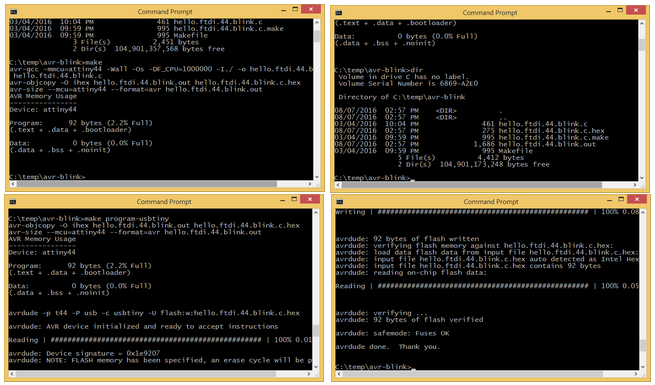
I have captured a sample compile/program cycle to show how avr-gcc works in tandem with avrdude, controlled by the makefile, to flash the attiny44 with my blink program. To start, copy the hello.ftdi.44.blink.c.make file to Makefile. Then run the make utility. This will generate the hello.ftdi.44.blink.c.hex file. To upload the .hex file to your ATtiny44 Hello board, simply call make with the correct programmer option, for example, make program-usbtiny
Click on the links below to download the C sourcecode and the makefile:
Programming: ATtiny44 Hello Board (Atmel Studio)
Atmel Studio is Atmel's integrated development platform (IDP) for developing and debugging Atmel's microcontroller products. Atmel Studio supports all AVR and Atmel SMART MCUs, providing a seamless enviroment for users to write and debug applications written in C/C++ or assembly language. The IDP is available as a free download.
Now in its 7th release, Atmel Studio 7 is integrated with the Atmel Software Framework (ASF), a large library of free source code with over 1600 project examples. Atmel Studio is based in Microsoft's Visual Studio environment and is available only for the Windows platform. The IDP comes with a built in simulator, which allows developers to visualize how the CPU's internal registers, interrupts and peripherals behave during program operation or in response to external stimuli.
One of the key reasons for writing programs in C/C++ using Atmel Studio or AVR-gcc is that it allow the developer full access to all the features and capabilities of the MCU. The microcontroller does exactly what the programmer has instructed it to do, unlike an environment like Arduino IDE, where a lot of the code details are hidden from the programmer. For this exercise, I decided to write a simple Hello World program (i.e. blink the on-board LED) on my Hello Board.
After downloading and installing Atmel Studio 7 on my PC, I clicked on the "New Project" link on the splash screen. Selecting File > New > Project leads to the same result.
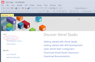
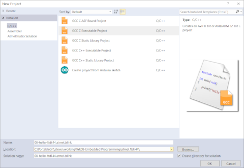
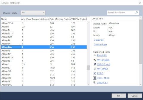
In the resultant dialog box, I selected GCC C Executable Project and entered the Name and Location details, then clicked OK. In the next dialog box, I selected ATtiny44A as the IC that I would be writing code for. Clicking OK brought me to the IDP desktop, with main.c on the left panel and the Solution Explorer tree on the right. I proceeded to write my program in main.c
    #include <avr.io.h>
    #include <utils/delay.h>
    #define F_CPU 1000000

    int main(void)
    {
        DDRB |= (1 << PB2);    // configure PB2 (LED) as output

        while(1)        // loop forever
        {
            PORTB &&= (0 << PB2);     // turn on LED
            _delay_ms(1000);          // wait for 1 sec
            PORTB |= (1 << PB2);      // turn off LED
            _delay_ms(1000);          // wait for 1 sec
        }
    }

Those familiar with programming in AVR-gcc would have spotted a number of syntax errors in the code from my pictures. It had been some time since I programmed in AVR-gcc and I was too lazy to look up the correct syntax, since I knew that the compiler would flag out these errors for me. For example, the correct code to include the delay routines in my program should be
    #include <util/delay.h>

instead of
    #include <utils/delay.h>

also, F_CPU should be defined as
    #define F_CPU 10000000

instead of
    #define F_CPU 10000000L
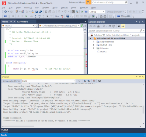
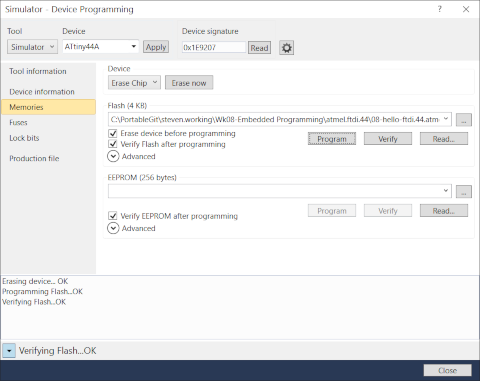
To compile my program, I selected Build > Build 08-hello-ftdi.44.atmel.blink. Any syntax or compiler configuration errors would be flagged out by the IDP. When Atmel Studio reports a successful build, this means that the software was able to generate the .hex program file, which can now be uploaded to the target board using a programmer.

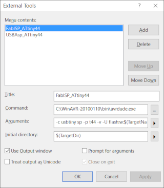
Atmel Studio has built-in support for Atmel's family of programmers, such as the AVRISPmkII. For other 3rd party programmers, you need to inform Atmel Studio that an external tool will be used. This is done via the Tools > External Tools option. Key in a name for the external programmer used, the location of avrdude.exe, the arguments to be used for your programmer and the initial target directory. $(TargetDir) and $(TargetName) are environment variables which point to the target directory and filename. I found that when I worked in the default Atmel Studio directory, I could use C:\WinAVR-20100110\bin\ as the initial target directory. However, when I used a non-standard directory for my files, this didn't work and I had to use $(TargetDir) instead.
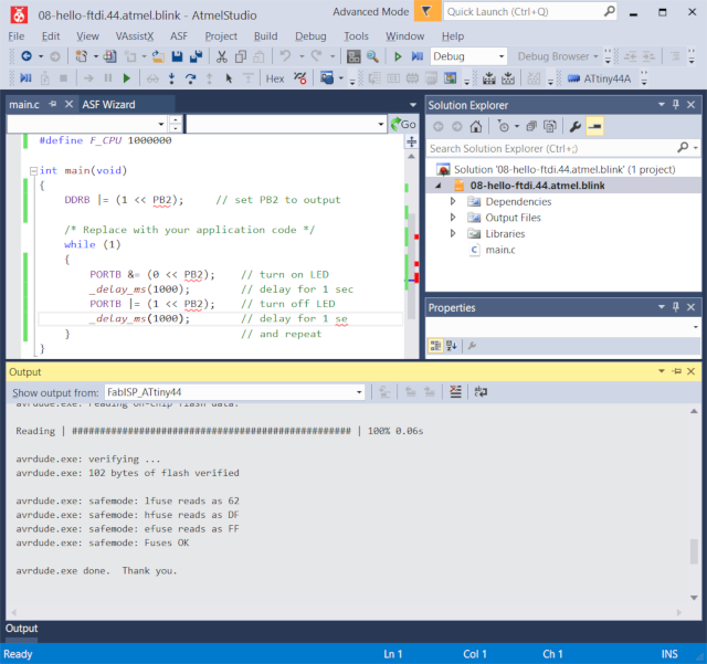
Once the external programmer options has been set up, it can be called by selecting Tools > <programmer>. For example, I uploaded my program to my Hello Board using Tools > FabISP_ATtiny44. If you are using one of Atmel's own programmers, then uploading your program to the target board is done by selecting Tools > Device Programming, selecting AVRISP mkII as the Tool and ATtiny44A as the device. Selecting Memories in the dialog window and clicking on the Program button uploads the hex code to the target board.
I did not replicate the "hero" shot of my Hello Board blinking, as it is similar to my earlier pictures.
My thoughts for this section? I think learning how to program the AVR family of chips in C/C++ is very important for any developer who works with this device. The Arduino IDE environment offers a quick and simple way to write programs for these devices, but many of the details are hidden from the programmer. The code generated is also non-optimised and you cannot really understand the MCU fully without interacting directly with the internal registers and peripheral. This is one area which I fully intend to explore and develop further. Probably my biggest complain about Atmel Studio is that it is only available for Windows OS. Atmel should consider offering it on Linux and OSX as well, perhaps using Mono or Eclipse as the IDE, in the same spirit that Atmel Studio uses Visual Studio as the base for Windows.
My programs for this section can be downloaded using the link below. The original filename was main.c. You could just open the file in a text editor and copy the code over to your own main.c in Atmel Studio:
Programming: ATtiny44 Hello Board (Assembly Language)
I had programmed in assembly language for a variety of microprocessors such as the Intel 8080, 8086/8088, Zilog Z80, Mostek 6502, Motorola 68000, 6805 and 6811 back when I was an undergraduate and just after I started working. In those days, systems were not as powerful and cross-compilers were not so readily available, so it was common to program in assembly language. Probably the last time I tried to program in assembly language was perhaps in the early 1990s.
Why program in assembly language? One view is that assembly language is for masochists who enjoy inflicting pain upon themselves :) A kinder view is that when you program in assembly language, you are talking to the microcontroller using its native language. Every assemby language instruction that you write results in a results in that same instruction being executed by the MCU, so assembly language code is small, highly optimized and fast. In the industry, assembly language is used when code size, speed and machine timing is very important and it is not uncommon to mix high-level with assembly language.
There are a number of nice references on programming in assembly language for the AVR family devices:
- AVR Assembler User Guide
- Beginner's Introduction the Assembly Language
- AVR Assembler Tutorial
- AVR Beginners
Let us look at an assembly language example from the avr-tutorials.com website:
/*
 *  Written in AVR Studio 5 / AVR Studio 6
 *  Author: AVR Tutorials
 *  Website: www.AVR-Tutorials.com
*/

.include "m8515def.inc"                  ; Header file for the ATMega8515
                                         ; microcontroller

                 LDI    R16,  0x00       ; Load 0b00000000 in R16
                 OUT    DDRB, R16        ; Configure PortB as an Input port
                 LDI    R16,  0xFF       ; Load 0b11111111 in R16
                 OUT    DDRC, R16        ; Configure PortC as an Output port

Again:           IN     R16, PINB        ; Read the values on the pins of PortB
                                         ; and store in R16
                 OUT    PORTC, R16       ; Write the value in R16 to the pins
                                         ; of PortC
                 RJMP   Again
Just like in C, there are 2 forms of comments. Multi-line comments begin with /* and end with */. Single line comments begin with a semicolon ; and anything after that is ignored by the assembler until the end of the line.
The .include "m8515def.inc" statement adds a header file to the assembly sourcecode. In this case, it adds the register and pin definitions for the Atmega8515 processor. The format of an assembly language instruction is:
  label: instruction operands  ;comment
e.g.
    Again:  IN  R16, PINB       ;read the values on the pins of PortB
The label: portion is optional and is often used to reference a point in the program for jump instructions (RJMP Again). R16, DDRB, DDRC, PINB and PORTC refer to microcontroller registers on the ATmega8515. To program in AVR assembly language, the developer needs to know the AVR instruction set (assembly language mnemonics) and register set for the selected microprocessor. This information can be found in the AVR Databook, where you have dedicated chapters for the individual families.
To test out assembly language programming on the AVR, I decided to write a simple Hello World program, to flash the LED on my Hello Board.
To create a new assembly language project, I clicked on File > New > New Project. In the resultant dialog box, I selected Assembler > AVR Assembler Project, then filled in the details for project Name and Location, then clicked OK. On the next screen, I selected ATtiny44A as my device.

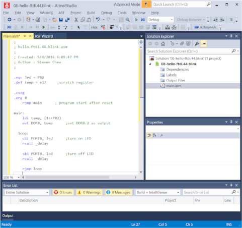
Atmel Studio then created the solution for my assembly project, with a template main.asm file. I typed in the code for my program into main.asm:
;
; hello.ftdi.44.blink.asm
;
; Created: 5/4/2016 6:09:47 PM
; Author : Steven Chew
;

.equ led = PB2

.cseg
.org 0
    rjmp main      ; program start after reset

main:
    ldi temp, (1<<PB2)
    out DDRB, temp		;set DDRB.2 as output

  loop:
    cbi PORTB, led		;turn on LED
    rcall _delay

	sbi PORTB, led		;turn off LED
    rcall _delay

    rjmp loop

_delay:
    ldi r18, 4
  out_loop:     ; outer loop label
    ldi r24, 0  ; clear r24
    ldi r25, 0  ; clear r25
  in_loop:
    adiw r24, 1     ; increment r24:r25
    brne in_loop    ; if no  overflow,

    dec r18     ; decrement outer loop
    brne out_loop
    ret
I began by defining PB2 as LED, then set the reset vector in the code segment to my program start location (main). In main, I first set DDRB pin 2 as an output. That completed the initialization code. Within a loop forever routine, I first cleared PB2, which turned on the LED. this was followed by a call to a delay routine. I then turned on the LED by writing a logic 1 to PB2, followed by another call to my delay routine. My delay routine consisted of a nested loop, formed by r18 (outer loop) and r24/r25 (inner loop). Rather than calculate the exact timing for my delay routine, based on the CPU clock speed and timing for each instruction, I simply adjusted the values by trial and error, until I had the delay I wanted - the lazy approach. For a more serious application, I would definitely calculate the exact duration of my delay routine.

To assemble the program to machine code, I selected Build > Build 08-hello-ftdi.44.blink from the menu bar. Once I had a successful build, I uploaded the hex code to my Hello board by selecting Tools > FabISP_Attiny44, the external programmer which I had configured earlier.

Atmel Studio creates a lot of files in the project solution, but you basically only need main.asm, which contains the assembly sourcecode. The rest will be re-created when you start your own new project. My assembly sourcecode can be downloaded using the link below:
Reflections - to be honest, I don't see myself coding in AVR assembly language much, unless I really need to use it, for example, when my project code requires very fast, lean code or when timing is crucial. Even then, I would most likely do most of my coding in C and assembly for only certain critical sections of code. It is not that I don't like assembly language - I cut my teeth programming in assembly language during my undergraduate days. I even had to do hand-assembly, because microprocessor systems were very primitive back then and high-level language was strictly restricted to mainframes. There are just too many wonderful machines and technology that I want to learn that assembly language is somewhere way down my list.
Neil is always encouraging us to document as we go along. It is something that requires a lot of discipline and a change in mindset. I am guilty of working on the machine or program, usually just taking screen captures and scribbling notes by the side, but not documenting it online. Sometimes, it is weeks or months before I get down to documenting the work and at times, I've had to recreate or redo the assignment, just to get the information correct. So my advice to all - please do as Neil says and not as I do - document your work as you go along!!!
Programming: ATxmega16E5 Hello Board
After hearing about Atmel's Xmega series and how wonderful they are, I made an Xmega Hello Board during this week, as I wanted to try it for myself. One of the first problems that I encountered was that the Xmega family required a different type of programmer. The FabISP and USBasp programmers that I had been using were unable to program Xmegas, which requires a PDI-based programmer.
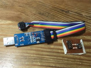
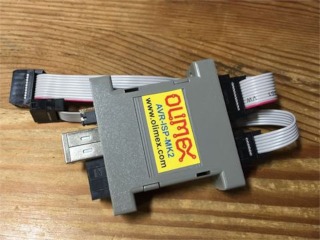
I looked up PDI programmers on the Internet and found some references to converting a USBasp to a PDI programmer. This appealed to the hacker in me and I immediately set about trying to modify one of my USBasps to become a PDI programmer. The hack required me to make a small interface board, perform minor "surgery" on my USBasp and burn in a new firmware. After trying for a couple of days, I still did not manage to get my modified USBasp to recognize my Xmega Hello board, so I finally caved in and ordered an AVRISP mkII clone from Olimex, which supported PDI programming.
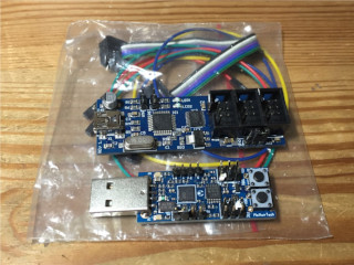
As I continued exploring PDI programmers for the ATxmega family MCUs, I came across another couple of programmers which seemed very interesting - the ZeptoProg II AVRISP mkII compatible programmer from MattairTech and an AVRISP mkII clone from aliexpress in China. Both these programmers are available at a much lower cost than the Olimex AVRISP mkII clone. The ZeptoProg II even has a 4ch logic analyzer and frequency output and measurement. Being the sucker that I am for technology, I promptly ordered one of each of those programmers for myself.
To program the Xmega Hello board that I built, I first started with the code that Neil had written for his Xmega Hello board. Looking at the sourcecode for Neil's hello.ftdi.16E5.blink.c, the syntax bore very little resemblance to that for the ATtiny and ATmega family devices. The Xmega processors used virtual ports (VPORT0, VPORT1, VPORT2 and VPORT3. The way to access the data direction register was also different from traditional AVR programming - VPORTA.DIR instead of DDRA. To write data to the output port, we use VPORTA.OUT instead of PORTA in traditional AVR programming. All in all, it is almost like learning a new programming language.
#define VPORTA VPORT0 // pre-mapped virtual port A
#define VPORTC VPORT1 // pre-mapped virtual port C
#define VPORTD VPORT2 // pre-mapped virtual port D
#define VPORTR VPORT3 // pre-mapped virtual port R
This section of code maps VPORT0 - 3 to virtual ports A-D.
   OSC.CTRL = OSC_RC32MEN_bm; // enable 32MHz clock
   while (!(OSC.STATUS & OSC_RC32MRDY_bm)); // wait for clock to be ready
   CCP = CCP_IOREG_gc; // enable protected register change
   CLK.CTRL = CLK_SCLKSEL_RC32M_gc; // switch to 32MHz clock
The next section of code (above) sets and switches the MCU to 32 MHz operation. The LED pin is configured as an output port by the statement VPORTA.DIR = LED, which was previously defined as PIN4_bm or PIN4 bitmask.
Once all the initialization code has been completed, the main routine runs within an endless loop. This routine turns the LED (connected to PA4 on, delays for a while, before turning the LED off again, followed by another delay. The whole process is then repeated.
   while (1) {
      VPORTA.OUT = LED;
      _delay_ms(DELAY);
      VPORTA.OUT = 0;
     _delay_ms(DELAY);
     }
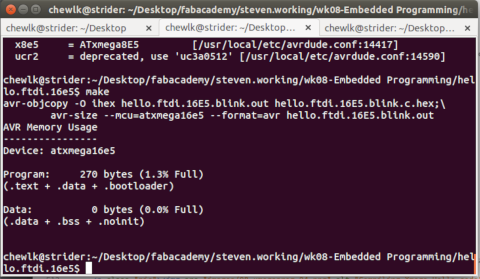
To compile the program, I copied an renamed hello.ftdi.16E5.blink.make to Makefile, then ran the make utility. The contents of hello.ftdi.16E5.blink.make:
PROJECT=hello.ftdi.16E5.blink
SOURCES=$(PROJECT).c
MMCU=atxmega16e5
F_CPU = 32000000
TARGET = x16e5
PROGRAMMER= atmelice_pdi

CFLAGS=-mmcu=$(MMCU) -Wall -Os -DF_CPU=$(F_CPU)

$(PROJECT).hex: $(PROJECT).out
	avr-objcopy -O ihex $(PROJECT).out $(PROJECT).c.hex;\
	avr-size --mcu=$(MMCU) --format=avr $(PROJECT).out

$(PROJECT).out: $(SOURCES)
	avr-gcc $(CFLAGS) -I./ -o $(PROJECT).out $(SOURCES)

program: $(PROJECT).hex
	avrdude -p $(TARGET) -c $(PROGRAMMER) -U flash:w:$(PROJECT).c.hex
The MCU is defined as the ATxmega16E5 and the MCU clock fequency is defined as 32 MHz. The program is compiled by calling make without any arguments.
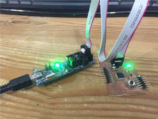
The compiled hex code was then uploaded to my hello board using one of the PDI programmers that I bought:
avrdude -c avrisp2 -v -p x16e5 -U flash:w:hello.ftdi.blink.c.hex
Since my Xmega Hello board had an RGB led, I decided to make use of it. I modified Neil's original code, to output different colors to the led:
#define DELAY 100 // blink delay
#define GREEN PIN4_bm // LED bit mask
#define RED PIN3_bm     // red led
#define BLUE PIN2_bm    // blue led
I declared the PortA pins controlling the 3 led colors and modified the code in the while (1) loop to run through the sequence of colors.
   while (1) {
      VPORTA.OUT = RED | GREEN | BLUE;
      _delay_ms(DELAY);
      VPORTA.OUT &= ~RED;
     _delay_ms(DELAY);
     VPORTA.OUT = RED | GREEN | BLUE;
     _delay_ms(DELAY);
     VPORTA.OUT &= ~GREEN;
     _delay_ms(DELAY);
     VPORTA.OUT = RED | GREEN | BLUE;
     _delay_ms(DELAY);
     VPORTA.OUT &= ~BLUE;
     _delay_ms(DELAY);
     }
Programming: Cypress PSoC Eval Board
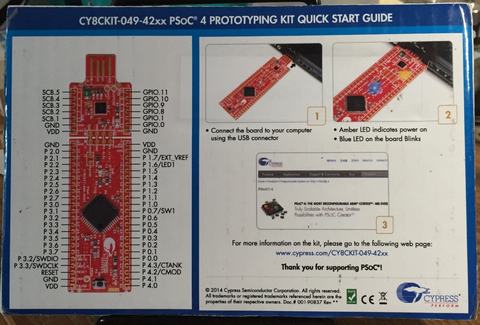
I was very excited to get my hands on Cypress' Programmable System on a Chip (PSoC) prototyping kit. The CY8CKIT-049-42xx is a PSoC 4 device, which basically means that it is an ARM Cortex M0-based device. There's a lot of power and functionality, all on a $4 board.
The first thing that I did, after getting the set was to look for documentation on how to use it. The kit came packaged in stiff cardboard, with a picture of the board pinout and instructions to go to CY8CKIT-049-42xx for information.
I found out that I needed to download and install Cypress' PSoC Creator software in order to work on the board. The PSoC 4 Prototyping Kit Guide gave me a very quick rundown on how to install the software and load and compile a "Hello World" project and upload it to the board.
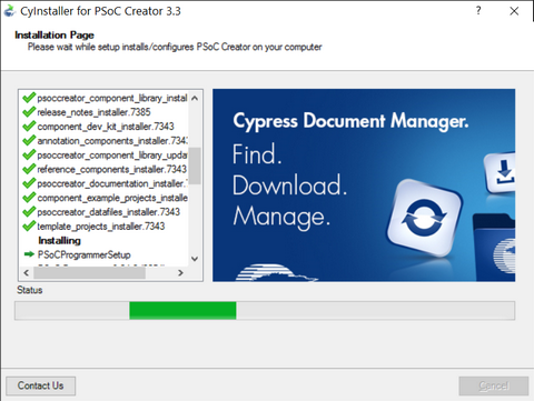
This screen capture image, taken from the PSoC 4 Prototyping Kit Guide, gives a very good overview of PSoC Creator and the PSoC development workflow.

There are 2 ways of programming the CY8CKIT-049-42xx: through the USB in bootloader mode or using a $90 programmer, the Cypress MiniProg3 Program and Debug Kit. Since we only bought the prototyping kit, I was limited to using the bootloader mode for programming the board. The PSoC Creator installation also included a lot of code examples, including the Bootloader files, which I needed.
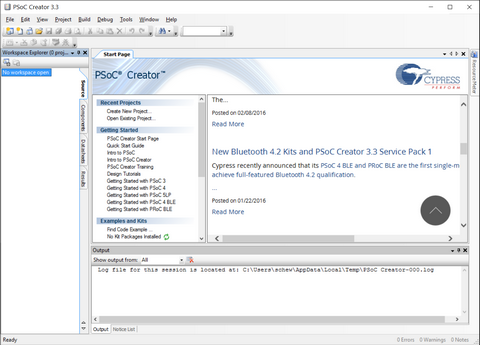
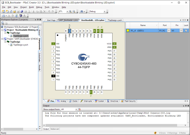
To open the "Hello World" Blinking LED project, I selected File > Open > Project Workspace and navigated my way to the the Bootloader code example at Documents > PSoC > SCB_Bootloader and selected SCB_Bootloader.cywrk.


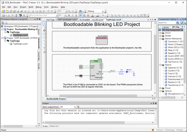
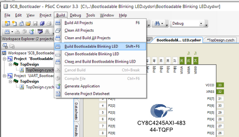
With the project workspace open, I right-clicked on Project 'Bootloadable Blinking LED' and set it as the active project. Double-clicking on TopDesign.cysch opened the schematic for the project. There are 3 configurable components in this project - the Bootloadable module, the PWM module and the digital I/O pin module. The 560 ohm resistor, LED and ground are considered off-chip components and do not need to be configured.
Cypress' PSoC line of products was first introduced in 2000. It was a radical departure from the traditional way of developing embedded products and requires a paradigm shift, but offers a more integrated approach to embedded development. Developers design their product using on a schematic, dragging and dropping components as required. They then double-click on the component to configure it and wire up the components based on their design. The PSoC chip is hardware customizable and developers can add in a wide range of peripherals, such as ADCs, timers, PWM, GPIO, amplifiers, multiplexers, communications modules and even capacitive touch sensing. Many of these peripherals can be mapped to user defined pins on the IC, leading to a very flexible design. Cypress' video series, PSoC Creator 101 Lesson 2: Introduction to PSoC gives a very good overview of the PSoC family and the design philosophy behind the chip.
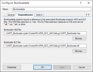
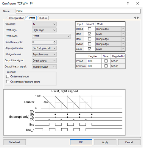
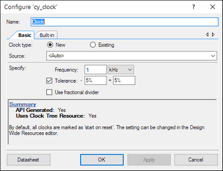
I first double-clicked on the Bootloadable module, selected the dependencies tab and navigated to the Bootloader HEX file, then clicked OK, to configure the bootloader code. I next selected the PWM module, clicked on PWM tab and filled in the values for the PWM period (1000) and compare (500). This gave me a 1 sec clock with 50% duty cycle. The next item to configure was the clock setting. Here, I configured the clock frequency to 1 kHz (1000 counts equals 1 sec blinking interval). I also H/W connection for the digital pin P1_6_LED and assigned it to pin P1.6 on the physical device (Project > Bootloadable Blinking LED Resource), as the USER_LED on the kit is connected to this pin.
Once all the component modules were configured, it was time to build the project. This is done by selecting Build > Build Bootloadable Blinking LED from the pull-down menu at the top. The compiler assembles and configures the components used in the design and generates the cyacd (Cypress Application & Code Data) file for the project. This is equivalent to the .hex file for AVR devices.
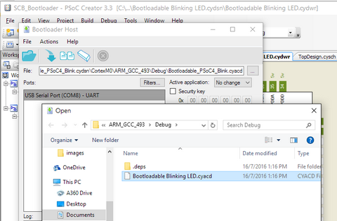
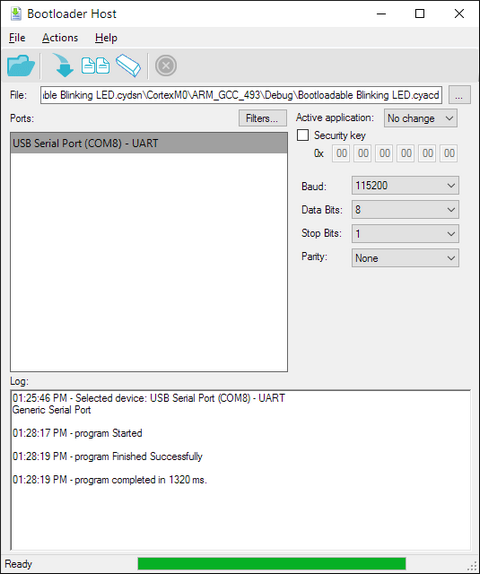
To upload the project file to the prototyping kit, I plugged in the module while pressing the push-button switch. This action puts the board into bootloader mode (indicated by quick flashes of the USER (blue) LED). Clicking Tools > Bootloader Host... brings up the bootloader. Click on File > Open and select the project .cyacd file. The default comms settings for the USB bootloader are 115200 bps, 8 data bits, 1 stop bit and no parity. Click on the Program (arrow) icon or press F5 to upload the program to the device. The USER LED on the board should now blink at the programmed rate.
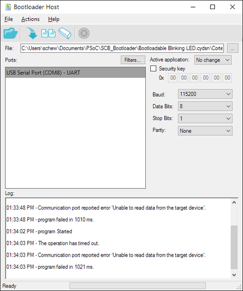
If you are unable to upload your code to the board using the Bootloader Host program, check that you have selected the correct COM port, comms parameters and that the board is set to Bootloader mode (fast blinking USER LED).
A short video clip of the board programmed to flash the LED for a very short duration, with a period of 1 sec:
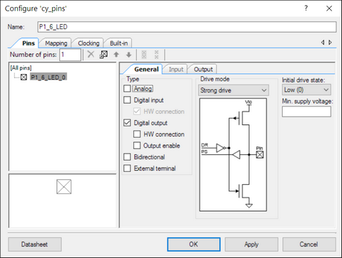
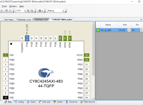
The code above used the PSoC hardware (PWM, clock) to generate the timing for the LED. I decided to try something different with my second program, controlling the LED via software instead. To begin, I created an empty PSoC 4 design. I then dragged and dropped the components that I needed into the TopDesign schematic. These were the Bootloadable module and the digital output pin. To make the design more understandable, I added a resistor, LED and ground to the schematic. For the digital output pin, I unchecked the HW connection checkbox, since I would be controlling the port using software. I then mapped the digital output port to P1.6 on the PSoC chip.
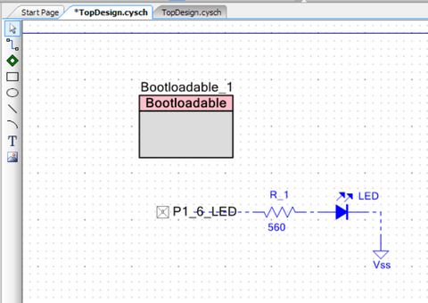
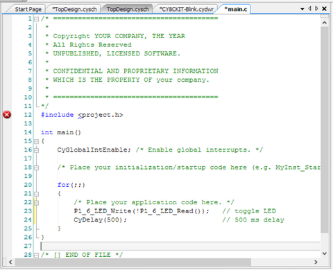
The next task was to write the C-code to toggle the LED, with a delay in between. I opened main.c in the PSoC Creator editor and added the following lines of code:
    for(;;)
    {
        /* Place your application code here. */
        P1_6_LED_Write(!P1_6_LED_Read());   // toggle LED
        CyDelay(500);                       // 500 ms delay
    }
The P1_6_LED_Write(!P1_6_LED_Read()) statement read the current status of the digital port, inverted the value and wrote it out again, toggling the LED. I called a library routine, CyDelay() to implement a 500 ms delay, giving me a 1 sec blink rate. After building the program, I uploaded it to the board and took a video to show the results.

Reflections: When I first started, I didn't really like this new style of developing programs, as it was very different from what I was accustomed to. The PSoC 4 Prototyping Kit Guide did not really explain the philosophy behind this paradigm shift either. However, after watching the 101 video series from Cypress, I started to think about how an engineer would typically design an embedded project and Cypress' approach with the PSoC platform does seem like a logical and more natural way to design embedded systems. Having such power in such a low cost board is also quite amazing. I don't think there are many vendors with equivalent solution to the CY8CKIT-049-42xx prototyping kit. That said, it still takes some getting used to.
Downloads: The first Bootloadable Blinking LED project is from the PSoC Creator code example. It is installed together with the software, so I will not provide the code. The zipped project files for my second program can be downloaded from the link below. Just unzip the files to your PSoC Creator project workspace and open the project file (CY8CKIT-Blink.cyprj).