Exercise 3 - Computer Controlled Cutting
Assignment
Assignment for this week is to:
- Design, make and document a parametric press-fit construction kit.
- Design and make anything on a vinyl cutter.
The Equipment
Here at Fablab Singapore Polytechnic, we have access to various models of laser and vinyl cutters, ranging from desktop models to floor standing machines, so we are pretty fortunate. Sounds nice, but we do have to contend with the rest of our user community (aka mainly students) and the laser cutters are basically booked solid, as students are rushing to complete their projects and assignments. The machines at Fablab SP:
- Epilog Fusion M2 40 (60W)
- EAS Laser - 70W
- Rayjet with rotary attachment - 30W
- Full Spectrum 5th Gen Laser x2 - 45W
- Roland GS-24 Desktop Viny Cutter
- Roland VS-540i A0 Plotter
Laser Cutter Assignment
First of is to determine the power and speed settings for our laser cutter. For this weeks's assignments, I will be using our Epilog Fusion machine, with 2mm stiff cardboard and 3mm corrugated cardboard. Using Epilog's recommended settings as a starting point, I drew a number of 20mm x 20mm squares and tried different combinations of speed and power in order to determine the optimal settings for the cardboard material that I will be using.

The same 20mm x 20mm squares can be used to determine the kerf for our Epilog laser. I measured the values of the outside edges of the square and the inner edges of the resulting hole. The difference in the 2 values, divided by 2, gives the kerf for each material. Using this technique, the kerfs for the 2 complete cuts were as follows:
| Laser Setting | Square (inside) | Hole (outside) |
|---|---|---|
| 10/50/50 | 19.84, 19.76 | 20.02, 20.14 |
| 15/50/50 | 19.86, 19.86 | 20.09, 20.02 |
From the values above, the worse case kerf can be calculated:
- 2mm cardboard (SPD/POW/FREQ 10/50/50): (20.14mm - 19.76mm)/2 = 0.19mm
- 2mm cardboard (SPD/POW/FREQ 15/50/50): (20.09mm - 19.86mm)/2 = 0.12mm

One conclusion that I can draw from the kerf measurements is that lower speed/higher power settings results in a larger kerf. This makes sense, as the laser, under those conditions, would burn away more of the base material. I drew the 20mm x 20mm squares in CorelDraw instead of Inkscape, for the simple reason that our Epilog laser is patched to a notebook with CorelDraw and shows up as a printer in CorelDraw. A screencapture of my CorelDraw test drawing is included and the file can be downloaded from here. The text was added to the drawing later.

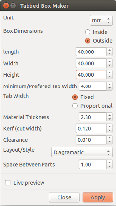
Once the kerf is known, it is very easy to create a standard box shape for laser cutting. You can generate the cutfile using the online Boxmaker website or Inkscape's tabbed box maker extension.
Note: One important point to note - Inkscape uses 90 ppi for jpg and png files, whereas CorelDraw uses 96 ppi. When exchanging files between the 2 platforms, you need to scale up or down by that ratio, i.e. when importing Inkscape files in CorelDraw, use a scale factor of 96/90 = 1.067

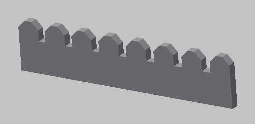
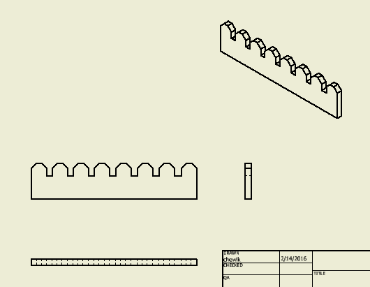
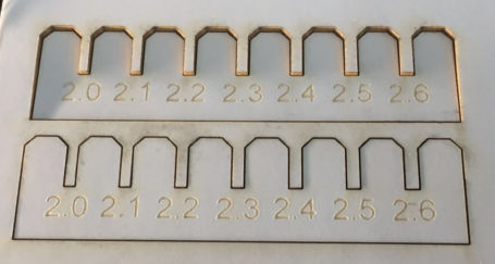
The next thing to do would be to determine the best notch size for my press-fit construction kit. I decided to model my notch designs in Inventor, as Inventor lends itself very well to parametric design. Since the kerf for our Epilog ranges from 0.12 to 0.19mm, for my 2.3mm cardboard, I decided to draw a series of chamfered notches ranging from 2.0 to 2.6mm in 0.1mm increments, i.e. +/- 0.3mm allowance from the nominal thickness of 2.3mm.
One of the issues that I had was how to move from my CAD model to the cutfile for our laser cutter. I modeled the part in Inventor first, but encountered some difficulty exporting the model to the dxf format required by Inkscape. File --> Save As and File --> Export didn't work for me initially and Inkscape is very particular about the version of dxf file that I can open.
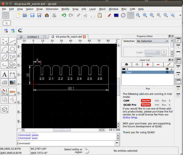
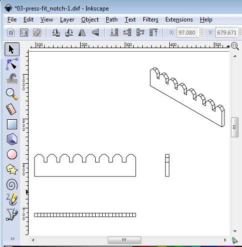
I tried opening the Inventor dwg and dxf file in QCAD & LibreCAD and had no issues with it. QCAD is able to export the svg model directly to Inkscape, using the File --> Quick SVG Export option. Along the way, I also decided to try model the lasercut notch test part in QCAD. Getting Inkscape to recognise the dxf file saved by QCAD and LibreCAD was another matter altogether. It can be a very frustrating experience.
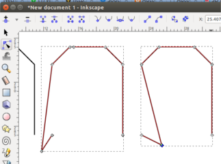
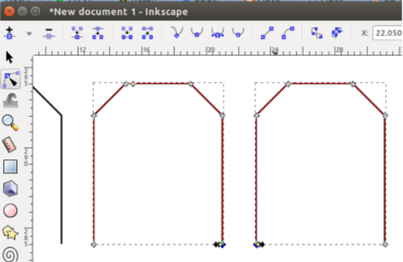
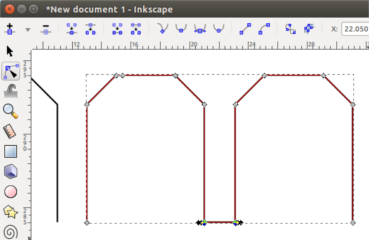
I also tried designing my press-fit notech test template in Inkscape but I encountered some difficulty trying to get my line to snap to existing endpoints when the endpoint did not fall on the grid intersection. This can be solved by using the Inkscape feature to join 2 end-points with a line segment. Note: The 2 nodes must be endpoints and not some intermediate points. Sometimes, nodes are superimposed over one another. This caused me some confusion and frustration for a while. The Inkscape model for my notch test is shown below.
After some more research, I finally found an Inventor to Inkscape workflow that worked. This required me to create an Inventor drawing file (.idw) and bring in my part in "base view". After that is completed, I needed to execute the File --> Save As --> Save As a Copy command. Make sure that the R15 Autodesk 2000 dxf format is selected. Click on the Options button and make sure that only the part geometry is exported to the dxf, as we do not need the dimensions and text. Open the resulting dxf file in Inkscape. Since I used the same units (mm) in both Inventor and Inkscape, I left the scale factor as 1x. Delete any unwanted parts, duplicate and position the parts for the cutfile. This file can be saved in svg format for the laser cutter. Inkscape even supports gcode generation, through the GCodeTools extension.
Result of the notch test - the best fit was obtained by cutting slots using a value of 2.1mm for a material thickness of 2.3mm. The difference is accounted for by the kerf of the laser.
Note: Instead of the round-about process needed to go from Inventor to Inkscape, I decided to use CorelDraw for my laser cutting. The workflow for moving from Inventor to CorelDraw is really simple. After the design is done in Inventor, select the face to cut. Right-click and select "export face as" and export the selected face as dxf. Import the dxf file into CorelDraw, move, edit and copy it as necessary. Send to laser cutter. So much less hassle compared to working with Inkscape.
Press-fit Box
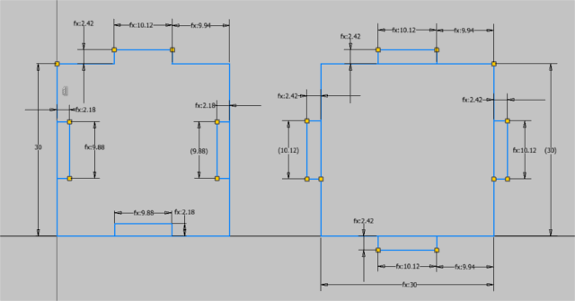
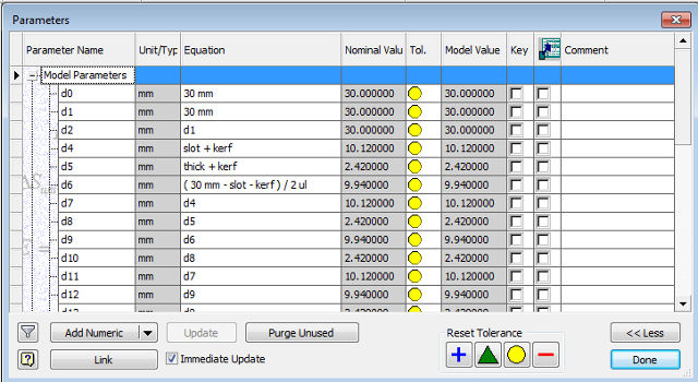
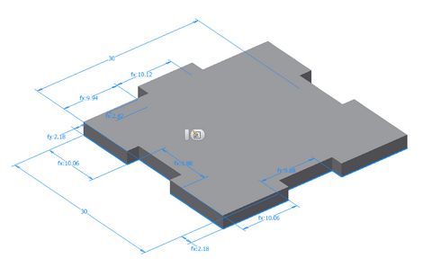
To test out the effects of kerf, I decided to build a simple 30 x 30 mm box. To make the design parametric, I decided to create 2 variables, slot and kerf and allow my design to be modified by changing the values for these 2 variables. For the "finger", I used a value of slot + kerf, since the laser cutter will burn away additional material. For the cutouts, I used a value of slot - kerf. The design is also adjustable for different thickness of material, but modifying the variable called thick.

When I started assembling the box, I realised I made a simple and fundamental error - since the box design was so basic, I didn't think about the inside dimensions after the box was assembled. I ended up with a box where the top and bottom pieces could not fit.
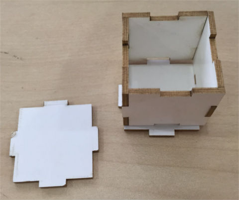
A quick way to resolve the problem would be to redraw the top and bottom pieces, with the "fingers" slightly off-center to account for the thickness of the cardboard along one edge. A much better solution would be to redesign my box for an internal dimension of 30mm and adjust the fingers & slots to accommodate the design.
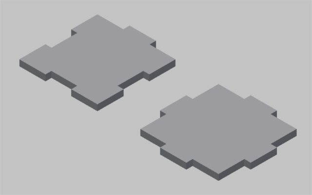
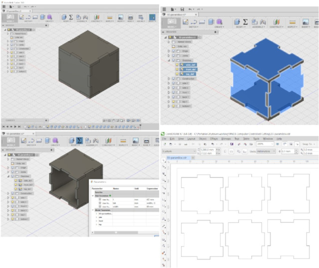
Since I have been using Fusion 360 for my final project, I decided to redraw my press-fit box as a totally parametric design, export the faces to dxf, then import them into CorelDraw for layout and laser cutting. The pictures below show the process. I designed my original box with a width of 30mm. To test if my design was fully parametric, I increased the width to 40mm and inspected the result. The larger box still fitted nicely as before, even with a larger width or board thickness.
A fully assembled version of my new box is shown below. Just for the fun of it, I decided to engrave all 6 faces with the fablab logo plus 2 other popular logos (Merlion, SG50) here in Singapore.


Press-fit Sphere
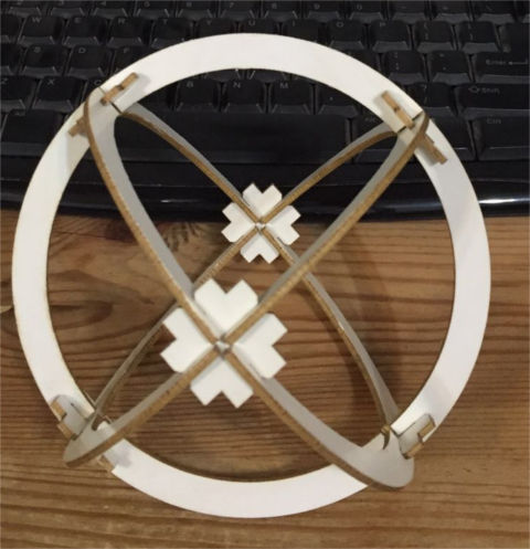
I decided to make the simple press-fit sphere from Instructables, as I find the design both simple and elegant. There are different ways to design the sphere. One method would be to design a single piece for the slot and connector each and duplicate the pieces. I decided to start with a concentric circle, then break-up the circle into the 4 sections I needed instead.
To make my design parametric, I defined thickness (t) and kerf variables. To work with materials of different thickness, all the user need to do is to change the t value. The kerf value would also have to be adjusted to match the new laser settings.


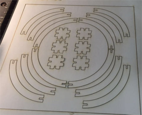
The next step would be to port it to CorelDraw, then duplicate the connector and slot pieces for the sphere, lay them out and send the design to the laser cutter. My final product, after laser cutting and assembling, is shown below. I've used a laser setting of SPEED (15)/POWER (15)/FREQ (15) similar to the earlier jobs. A slot value of 2.1mm for cardboard thickness of 2.3mm gave a very good fit. I can hold the assembly up with one finger along the connector, without the kit coming apart.
Living Hinges
I am also interested in living hinges as part of my Week 3 assignment. I tried installing both Kokopelli and Antimony as Ubuntu and Xubuntu VMs on my computer. After many attempts, I managed to get Antimony working on my Xubuntu VM. I'm still unable to get Kokopelli (both full and retro versions) working on Ubuntu up to this point. When I tried to compile from source, I keep getting errors, so it is somewhat frustrating.
I intend to continue my explorations into Antimony and Kokopelli as the idea of writing code to produce 3D models sound somewhat appealing. I immediate target for Kokopelli is to use it to produce a design for a living hinge.
Update - Living Hinges
I have been intrigued by the idea of living hinges ever since I first heard about them from Neil during Fab Academy last year, but never found the time to go any further. I find the idea of creating flexible, bendible objects from wood or acrylic by just cutting certain patterns very fascinating.
I still haven't gotten around to designing my own living hinge projects yet, but I decided to make a couple of living hinge products using our laser cutter for our Fablab booth at innovFest unBound Exhibition at Marina Bay Sands in May this year.
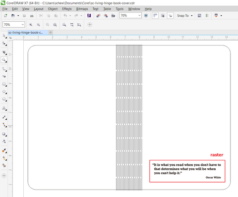
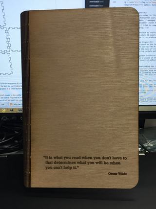
I started off by downloading the Lasercut Flexible Book Hinge project from Epilog's Sample Club. The download file is in CorelDraw format and is ready for output to a laser cutter without any modifications. The text is engraved (raster) and the rest of the image is cut (vector).
The settings that I used for the raster and vector process (2.6 mm plywood, Epilog laser) were:
- Raster: speed (60) power (70) frequency (30)
- Vector: speed (20) power (80) frequency (50)
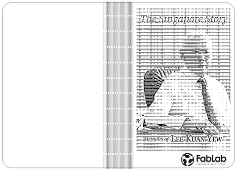
Once I found that I could successfully make a living hinge book cover, I decided to customize it to one of the books that I owned - The Singapore Story, by Mr Lee Kuan Yew, Singapore's founding Prime Minister.
I started off by removing the text from the flexible hinge book cover that I downloaded from Epilog's Sample Club. I then searched online for a scanned image of the book cover, with sufficient resolution for my laser engraving. The next step was to convert the image to a form suitable for engraving on wood. To convert the image using CorelDraw, I followed the procedure in Epilog's knowledge base article.
- 1. Open the photo in CorelDraw, resize and crop to the final size for engraving.
- 2. Select Bitmaps > Resample... from the drop-down menu and resample the image at 600 dpi.
- 3. Apply Gamma Filter (Effects > Adjust > Gamma), value 3.5 to reveal details in low contrast areas of the photo.
- 4. Apply Unsharp Mask filter (Bitmaps > Sharpen > Unsharp Mask), with Percentage 500, Radius 20 and Threshold 6.
- 5. Open the Sharpening palette and enter the values Edge Level (%) 100, check Preserve Colors and set Threshold to 70.
- 6. Select Bitmaps > Mode > Black and White (1-bit) to convert the image to Black & White (1-bit), using Halftone dithering (best for wood). Recommended values: select Line as the Screen type, 0 degrees and 100 lines per inch.
- 7. For the actual engraving, I selected Speed 60%, Power 80%, 600 dpi and Jarvis dithering.
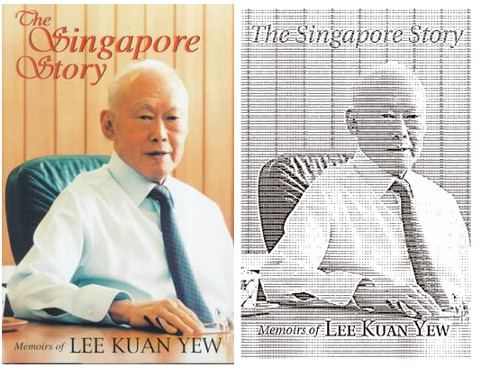
I added the logo for Fablab Singapore Polytechnic, then sent the output to our Epilog laser cutter. The final result is shown below:

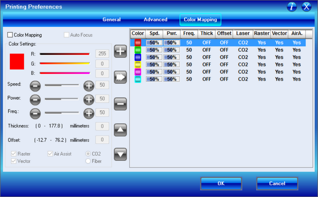
Laser Color Mapping
The Epilog laser that we have allows customize the laser settings using a color palette. This is one area that I would like to investigate further, as it would allow me to have different settings for cutting and engraving, by drawing my design using different colors. For example, I could customize the color palette such that a full black hairline (0.010mm) would result in a complete cut, whereas a square drawn in red would result in the shallowest depth of cut, allowing me to score lines for folding.
The Epilog color mapping setting is shown in the following picture.
The design files for my laser cutter assignment are in the links below:
- Inkscape Tabbed box maker
- Kerf comb - qcad model
- Kerf comb - inventor/coreldraw model
- Simple box - inventor/coreldraw model
- Parametric press-fit box in Fusion360
- CorelDraw cutfile for parametric box
- Press-fit sphere - 70mm diameter
- Flexible book cover (Epilog sample)
- Singapore Story_book cover
Vinyl Cutter
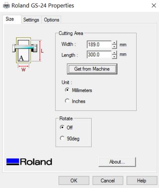
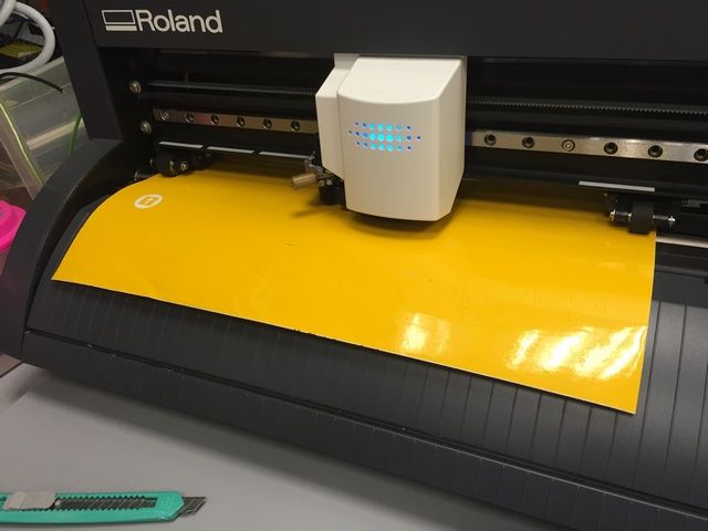
The Roland GS-24 is the successor and upgrade to the popular GX-24 Desktop vinyl cutter. The vinyl cutter is most commonly used to make signs and stickers, but it offers so much more. For example, it can be used to make pop-up cards, fashion accessories and even flexible electronics circuits.
When setting up the GS-24, it is important that the cutting blade be adjusted correctly, as too much of the blade showing wil lead to over-cut and too little will give rise to a shallow depth of cut and difficulty in weeding the cut material. A good tutorial on the proper setup of the GS-24 is available here.
The GS-24 comes with Roland's own Cutstudio software, which is available either as a standalone application, a plugin to Adobe Illustrator or CorelDraw. For this exercise, I've installed both the standalone Cutstudio application and as a CorelDraw plugin.

Roland CutStudio
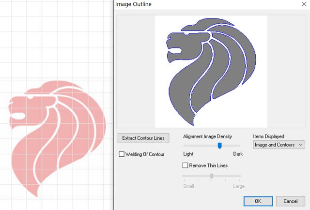
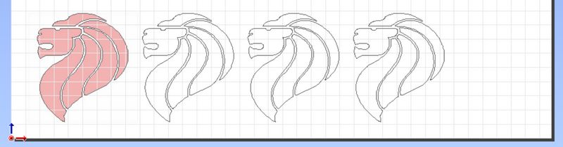
For my first design, I decided to make a vinyl cutout of the Singapore Lion head design. To do this, I downloaded a picture of the Singapore lionhead from the Internet and imported it into Cutstudio. After resizing the image, I selected Object/Image Outline from the menu bar and clicked on the "Extract Contour Lines" button in the Image Outline dialog box, followed by the OK button.
The GS-24 has a very useful feature, where the CAMM-driver talks to the machine to determine the size of the vinyl sheet. This info is then used to configure the size (width, length) of the drawing area, so that the user's design will always be within the size of the vinyl sheet.
I duplicated the Lionhead design before sending it to the vinyl cutter, so that I have a few copies that I could hand out to some of my colleagues.
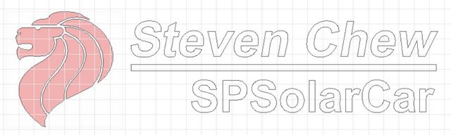
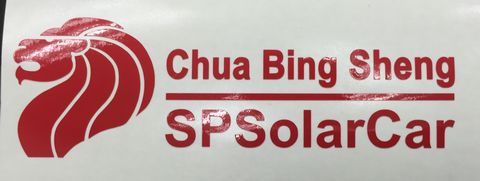
Next up was to design and cut a few personalized vinyl stickers for myself and some of my colleagues in our SP Solar Car team. After the design has been cut out, I weeded the unwanted parts, put a transfer tape onto the remaining vinyl sticker and passed these onto my colleagues.
Roland's Cutstudio makes it really very easy to design and print vinyl stickers. Learning the software is a simple 10-minute affair. There is a major limitation of the Cutstudio applicaiton though - all designs are saved in Roland's proprietary .cst file format, so Cutstudio is needed to view and edit the files.
Designing with Inkscape
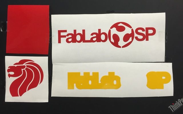
For a last design with the vinyl cutter, I decided to make a stylised Fablab@SP logo for myself. I started by importing the Fablab logo which I downloaded from the Internet into Inkscape. The Path/Trace Bitmap option allowed me to convert the Fablab logo into a bitmap. I then added some text around the Fablab logo, to form a stylised "FabLab@SP" design. The text is converted into path using the Path/Object to Path option. I adjusted the position of the text by bringing them all closer together to give the words more impact.

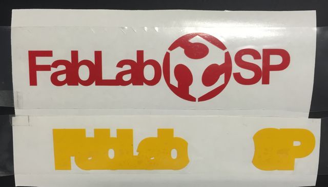
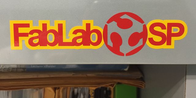
To give a yellow outline to my design, I saved the design as a png, opened it in Photoshop, selected the design and feathered the selection. I then re-imported the design into Inkscape and converted the feathered image into another contour. The main FabLab@SP logo and the feathered version were cut as two separate sheets. After weeding the unwanted material and transferring it onto a transfer tape, I decided to paste the logo onto the cupboard door in my office. The result looks quite different - the yellow background makes it stand out :)
The design files for my vinyl cutter assignment are in the links below:
- Singapore Lionhead design
- Lionhead sticker for SPSolarCar team
- Inkscape Fablab@SP file
- Cutstudio Fablab@SP file
Vinyl Cutter References
These were some of the references I used: