Exercise 2 - Computer Aided Design
Assignment
Our assignment for this week is to model (draw, render, animate, simulate, etc...) a possible final project and post it on your class page.
Seems like a simple assignment, but there's really a whole lot of work involved. We're supposed to model our final project using a wide range of software: 2D raster, 2D vector, 3D CAD, simulation, animation, audio and video editing. And we are supposed to use a number of software in each category. Being right slap in the middle of the Chinese New Year doesn't help either, as I'm going to be very busy over this period :D
2D Raster - GIMP
First up is a 2D raster software. I have some familiarity with Photoshop & Photoshop Express, but mostly for photo-editing, as I am also interested in photography. I've done things like cropping, resizing, adjusting gamma, photo-retouching and stuff like that, but not drawing & sketching on Photoshop.
I've decided to use GIMP as my 2D raster software as it is free and cross-platform, so this ties in very well with the Fablab philosphy. I've used GIMP previously to crop and resize photos, but again, not for sketching.
GIMP is available from http://www.gimp.org and there are some very good beginner tutorials at that site. A good starting tutorial is GIMP Quickies. The tutorial is available here.
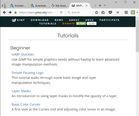
The GIMP Quickies tutorial covers the 4 main points:
- Changing the Size (Dimensions) of an Image (Scale)
- Changing the Sie (Filesize of a JPEG)
- Crop an Image
- Rotate or Flip an Image
Sketching with GIMP
Sketching with GIMP utilises the Layer feature. Start with a bounding box which gives the overall size of your project. Create a new layer and sketch on that layer for each new subsystem/section. For example, I have a base layer called "Background", then layers for my CNC Boundary (Box), the Base & X-axis (Base), Movable Bed (Bed), side support (Side), Y & Z-axes support (Y & Z) and motor section (Motors)

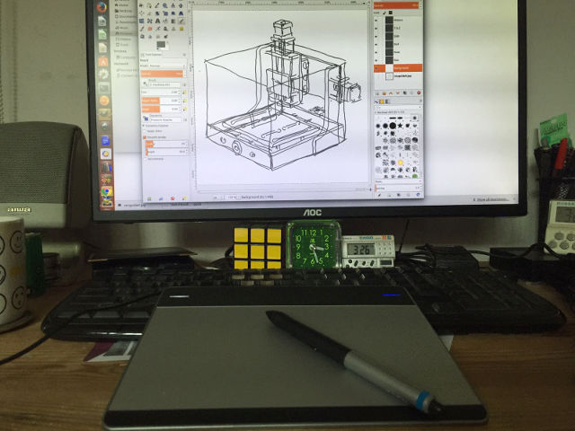
When doing any sketching, whether in GIMP, MyPaint, Inkscape or Illustrator, having a graphics tablet, such as a Wacom Cintiq or Intuous helps tremendously, as I have always found it difficult to sketch with a mouse. You should also place your tablet just in front of the monitor and keep your eye on your monitor as you draw, not on the tablet.
Converting an image to a sketch is very important when doing laser engraving. In GIMP, this is not quite as straight-forward as in some other graphics applications. One of the references that I came across on the Internet recommends the following procedure:
- 1. Load original image
- 2. Apply Sobel edge detect (Filters > Edge-Detect > Soebel)
- 3. Equalize and Desaturate the image (Colors > Auto > Equalize and Colors > Desaturate)
- 4. Adjust color curve for high pass filter, to bring out strong edges and eliminate edges with small magnitude)
- 5. Create an edges mask using Layers & Channels
- 6. Save the image once desired effect is achieved

I've tried doing this in GIMP. There are too many steps in the workflow from photo to sketch and it is not very easy to adjust the parameters in order to get a nice sketch effect.
While helping my colleague, Kai Chi, with his assignment, I came across a nice set of plugins for GIMP, which converts photos to sketches, with much less effort. The plugin is called Script-FUs Pack and provides more than 100 scripts for common filters and effects. The plugin can be download from the link I provided above. Installation instructions are also in the same link. Script-FU Pack was orginally written for GIMP 2.4, but has been updated to work with GIMP 2.8 as well.
Converting photos to sketches with Script-FU is very easy. All you need to do is select Script-FU > Sketch from the top menu bar. There are various options available. I just chose Quick Sketch. The resultant image is shown below:

2D Vector - Inkscape
Inkscape is a 2D vector drawing program. Unlike programs like GIMP and Photoshop, which works on images at the pixel level, Inkscape manipulates object using a series of mathematical equations. For example, a circle in Inkscape would be described by the coordinates of its center and its radius. This makes manipulating objects in Inkscape a lot easier than in 2D raster programs.
Inkscape can be downloaded from http://inkscape.org. Versions are available for Linux, Mac OS X and Windows. To install inkscape for Ubuntu:
  sudo add-apt-repository ppa:inkscape.dev/stable
  $ sudo apt-get update
  $ sudo apt-get install inkscape
The Inkscape official & community tutorials can be found at this link. 4 useful tutorials are:
A very useful feature of Inkscape is the ability to convert objects to path, perform path manipulation (union, difference, intersection) and to generate the cut path for the object. Here, in this example, I've taken our Fablab Singapore logo and converted it into a path, which can then be sent to a vinyl cutter or cnc.

Inkscape supports numerous plugins and extensions. Gcodetools allows a user to convert a path in Inkscape to gcode for a CNC machine. Gcodetools can be downloaded from GitHub. Once downloaded, extract gcodetools-dev.inx and gcodetools-dev.py to the Inkscape extension folder. In can be accessed via the Inkscape Extensions pull-down menu.
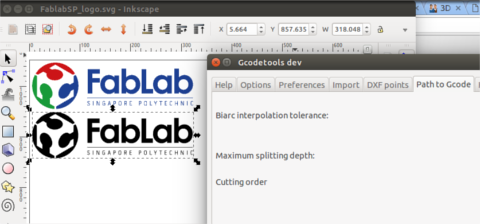
The figure below shows a cnc cut file brought into Inkscape and converted into SVG. The gcode for this cut file can be generated using GCodetools and the cnc parts either sent to a 2D router or laser cutter to make the parts. My Inkscape cutfile can be downloaded from here.

3D CAD Software
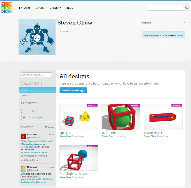
Tinkercad
Tinkercad is a browser-based 3D modelling software that uses constructive solid geometry (CSG) applied to a series of 3D primitive objects to create the 3D model. Tinkercad is very simple in operation and has a very short learning curve. However, I feel that it is somewhat limited when it comes to creating more complex 3D models.
You can sign up for a free account at www.tinkercad.com
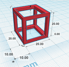
In one of the introductory classes that I taught in Digital Fabrication, participants were required to design a simple 3D model which cannot be created using subtractive manufacturing and realise the design using a 3D printer. The example that we used to illustrate the concept was a wire-frame cube, with a sphere inside it.
The figures below show how Tinkercad can be used to create the wire-frame cube model.
 |
 |
 |
OpenSCAD
OpenSCAD is a cross-platform, script-based, parametric 3D modelling software, using CSG to create 3D models. The learing curve for OpenSCAD is slightly longer than that for Tinkercad, but is relatively easy to pick up, especially for programmers.
OpenSCAD can be downloaded from www.openscad.org. The user manual and tutorials can be found in the documentation page. There is also a very good tutorial within the package itself.
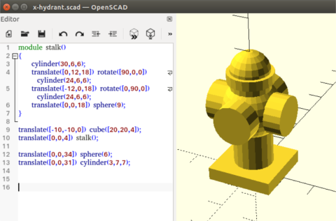
The figure below shows an example of an OpenSCAD script to create a fire-hydrant like object.
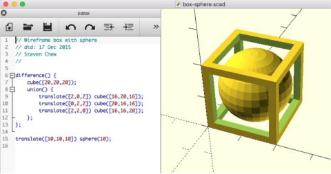
The equivalent OpenSCAD script to create a wire-frame cube with a sphere inside it is shown in the figure below.
Autodesk Inventor
Inventor is a full-featured parametric 3D modelling software from Autodesk. Fusion 360 allows collaborative design, with the project files saved on the cloud. Inventor is available to Fablabs and education free, which makes it a very attractive software package for use in 3D design. The learning curve is quite steep though.
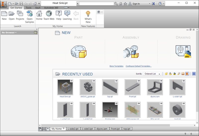
When the software is first launched, the Home screen is displayed, which allows users to view their most recent used files, create new parts, assembly or drawing.
Inventor parts have a .ipt file extension. Assembly files have a .iam file extension. In the bottom-up approach, users create individual parts first, then put them all together in an assembly file. In the top-down approach to design, users start with the assembly and work their way down to the individual component parts. The approach to use depends on the individual user and the design.
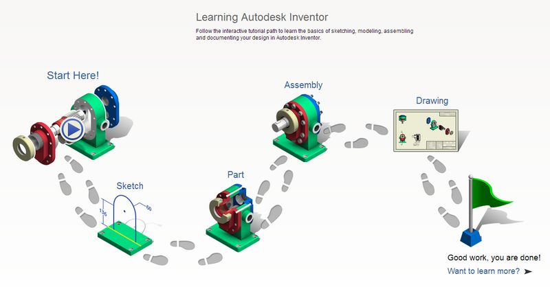
Clicking on the Help icon brings up the Inventor Getting Started and Tutorial help, which is a very good resource for learning the package. Other useful online references and tutorials that I have used are:
- Autodesk Academy
- Inventor Essential Training (Lynda.com)
- Introduction to CAD/CAE Tools (Carnegie Mellon Universit)
For my proposed final project, I started off by designing the framework for the DIY CNC machine and putting the parts together in an assembly file. The design is still preliminary, so many of the details have not been finalised yet. Since the machine is meant to be low cost, I have decided to design the framework for 12mm MDF or plywood. The working area of the CNC is 200 x 300 mm. The design can be scaled up to provide a larger work area.
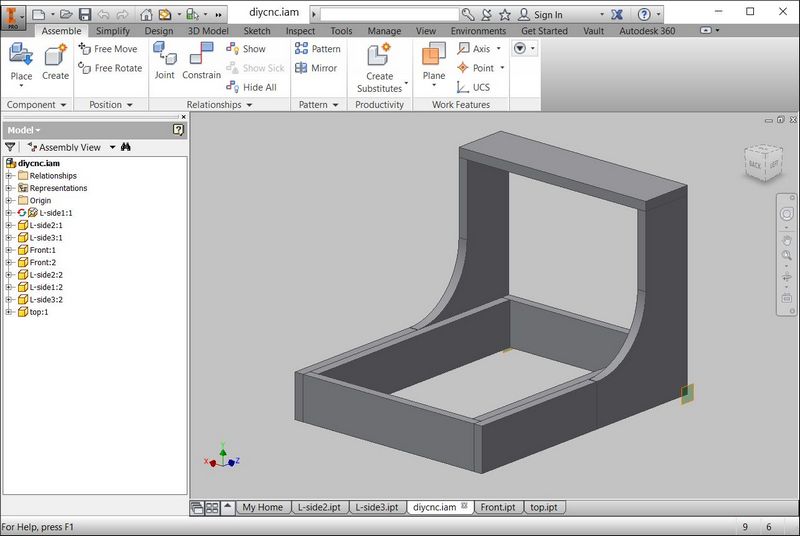
The assembly file can be downloaded from here - 02-diycnc.iam.
Antimony
Antimony is a 3D CAD software, where the user programs his 3D model using CSG, very similar to OpenSCAD. The major difference between Antimony and OpenSCAD is that Antimony has a much nicer graphical user interface and the user can also work directly on the 3D model generated, with a series of mouse clicks.
Antimony was developed by Matt Keeter at MIT and released into the public domain. Antimony basically
- teaches the user to think and organize his ideas better
- lets the user automate routine jobs, saving time
- fun to play with - user see the effect of their code immediately
Antimony has several dependencies:
- Qt open source
- libpng-dev
- python3-dev
- liboost-all-dev
- libgl1-mesa-dev-lts-utopic
- git
After Qt is installed, run the following dependencies:
  sudo apt-get install build-essential
    sudo apt-get install libpng-dev
    sudo apt-get install python3-dev
    sudo apt-get install libboost-all-dev
    sudo apt-get install libgl1-mesa-dev-lts-utopic
    sudo apt-get-install libgl1-mesa-dev
    sudo apt-get install lemon
    sudo apt-get install flex
Download Antimony from GitHub:
  sudo apt-get install git
    git clone https://github.com/mkeeter/antimony /opt/
Build Antimony:
  cd antimony
    mkdir build
    cd build
    /opt/Qt/5.4/gcc_64/bin/qmake ../sb.pro
    make -j8
And create a symlink:
ln -s /opt/antimony/build/app/antimony /usr/local/bin/antimony
The Open3dge article contains the full set of instructions, including a script to install Antimony.
The figure below shows the wire-frame box model with an embedded sphere, created in Antimony.
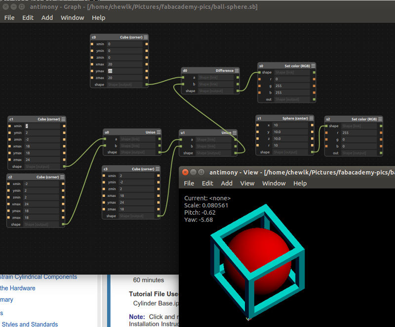
The Antimony file for the model: box-sphere.sb