Final Project Development - The Notes
Tasks:
To complete the final project and tracking the progress:
- What tasks have been completed? And what tasks remain?
- What has worked? And what hasn't?
- What questions need to be resolved?
- What have been learned?
What tasks have been completed? And what tasks remain?
Tasks completed:
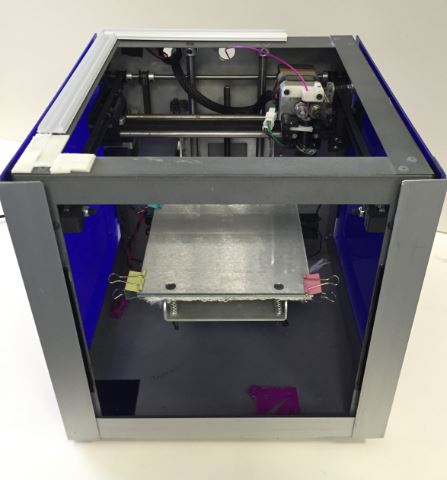
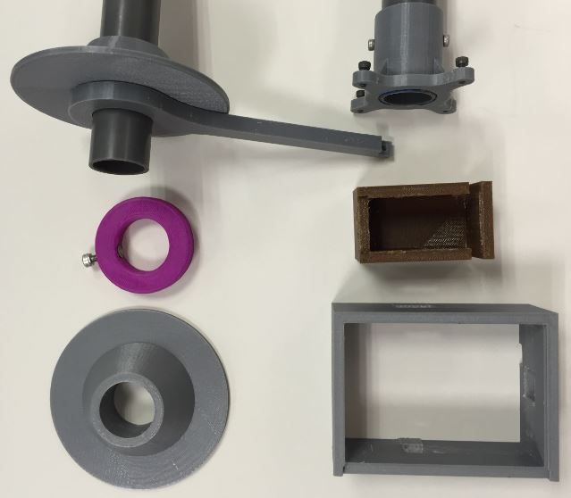
- 1. Found 1 old 3D Printer (Fab box - Solidoodle).
Tasks to be completed:
- 1. Writing the programing sketch in Arduino IDE.
2. Testing the functionality of the "Inspector for 3D Printer" system.
3. Final packaging, documentation and presentation to everyone.
What has worked? And what hasn't?
- 1. Line sensor and relay module are tested working with Arduino UNO.
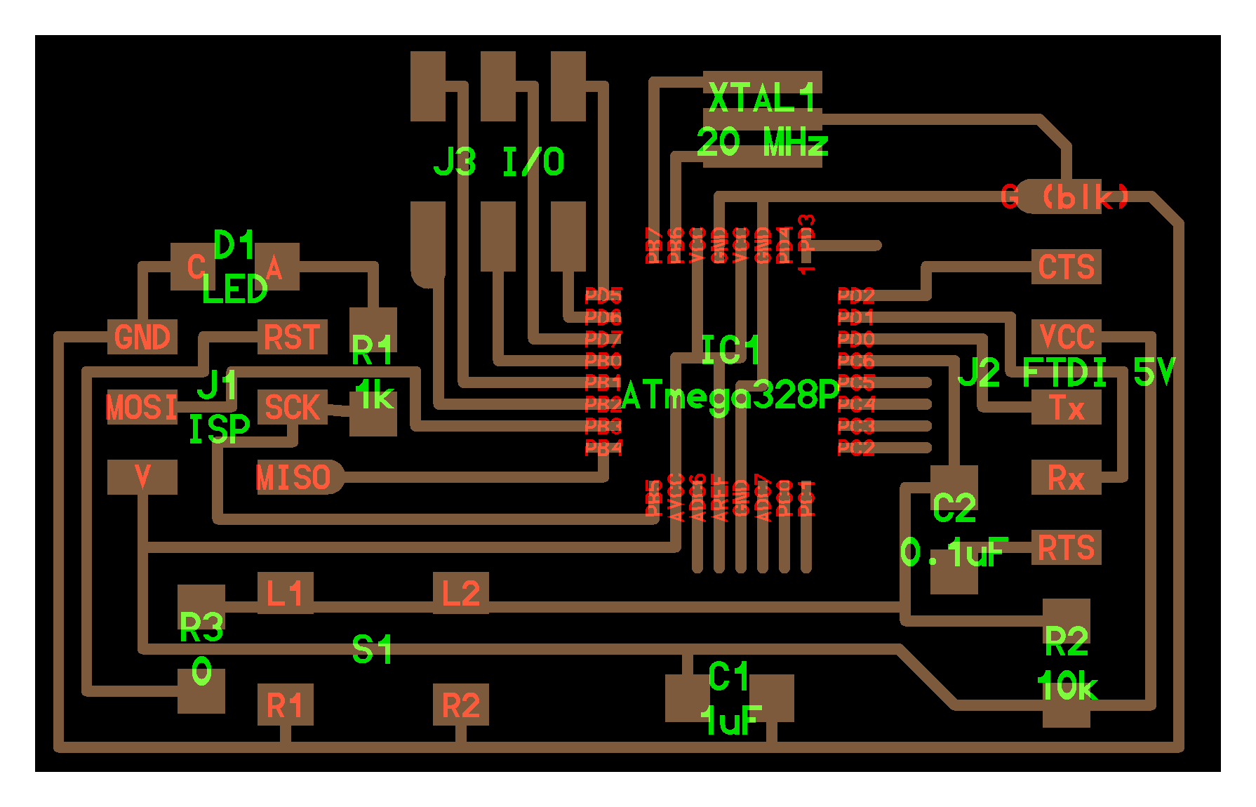
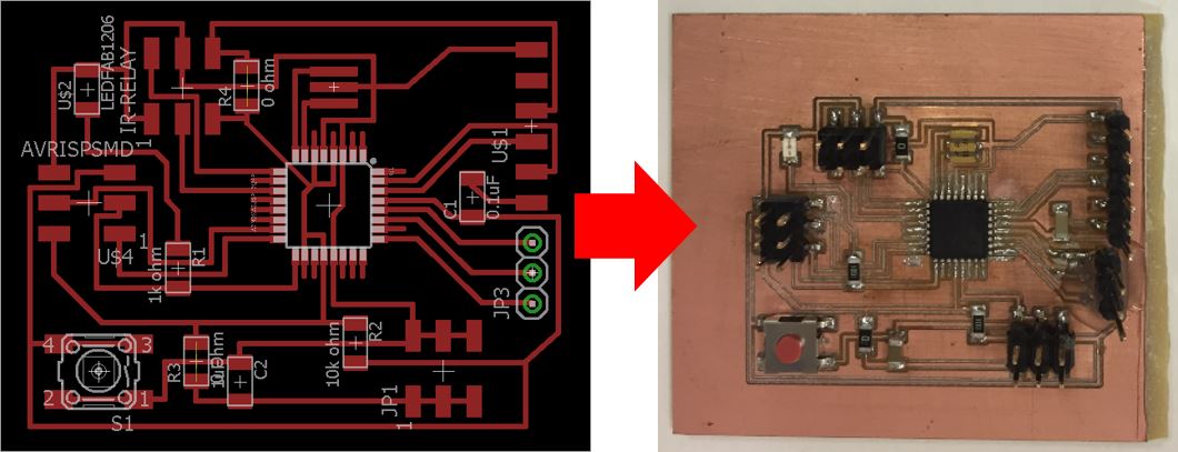
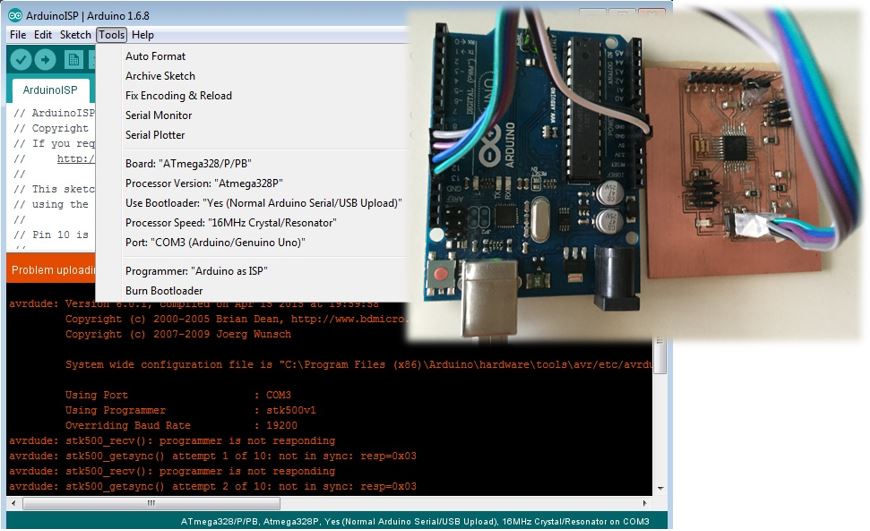
2. Self-made ATmega 328 micro-controller board is having error, ie. unable to burn bootloader.
What questions need to be resolved?
- How to solve the bootloader issue?
What have been learned?
- Alot had been learnt while in the progress to complete the task, ei. from self-reading, peers and "gurus". For examples, selection the right components/methods for a task (Where shall I position my relay module? on the AC side or DC side of the 3D printer; what is the better method to be used as an input to give signal to activate relay module? Weight sensor, IR sensor, Laser sensor.), trouble-shooting the sketch program, etc.
Notes Taken during the Development Process
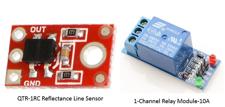
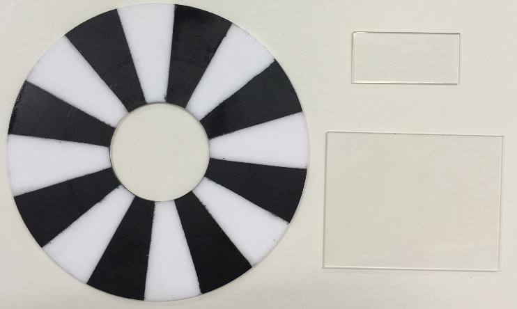
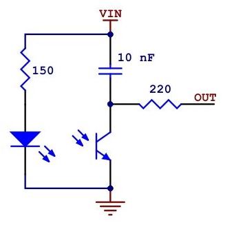
Reflectance Line Sensor
Specifications:
- Operating voltage: 5.0 V
- Supply current: 25 mA
- Output format: digital I/O compatible
- Optimal sensing distance: 0.125" (3 mm)
- Maximum recommended sensing distance: 0.375" (9.5 mm)
The LED current-limiting resistor is set to deliver approximately 20-25 mA to the LED when VIN is 5 V. The current requirement can be met by some microcontroller I/O lines, allowing the sensor to be powered up and down through an I/O line to conserve power. The following shows the functional circuit diagram of the line sensor. More information can be found from this link.
Arduino library for the Pololu QTR reflectance sensors can be downloaded here. Unzipped the folder and place it at Arduino's libraries in local C:\ drive.
1-Channel Relay Module
Specifications:
- Control Voltage: 5V DC
- High Input voltage trigger
- On-board LED to indicate the working status
- Max. Control Capacity: 10A@250VAC or 10A@30VDC
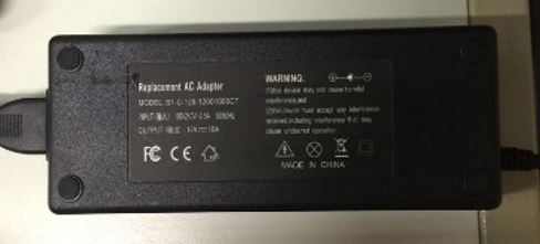
Power Supply for the 3D Printer
Specifications:
- Input voltage: 100-240VAC
- Input current: 2.5A
- Frequency: 50/60Hz
- Output voltage: 12VDC
- Output current: 10A
The followings were the references read.