Week 16 - Interface and Application Programming
Task:
To write an application that interfaces with an input &/or output device made.
This task will use the bluetooth on an Android smartphone to turn on/off the LED on ATmega328 chip and to send message back to smartphone on the LED status.
The following key componentss are needed to perform this task:
Step-by-step to perform the task
1. Android programming needs Java SDK. Thus, download and install JAVA SDK. Next, download and install the Android Studio.
2. In this task, the standard example of Android bluetooth interface apps (called Bluetooth Chat) will be adopted. First, launch the Android Studio>>Import an Android code sample>>Bluetooth Chat>>Define the apps' name and location>>Finish.
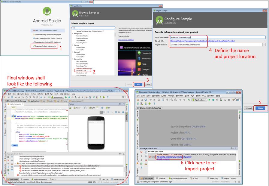
N.B. Secured bluetooth connection is preferred and the unique UUID was adopted from Solderer TV.
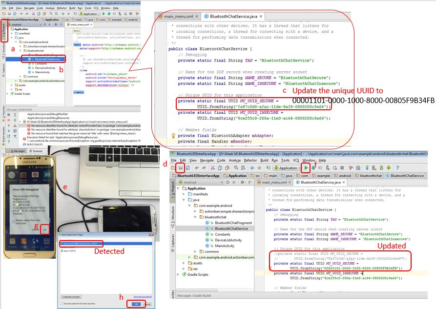
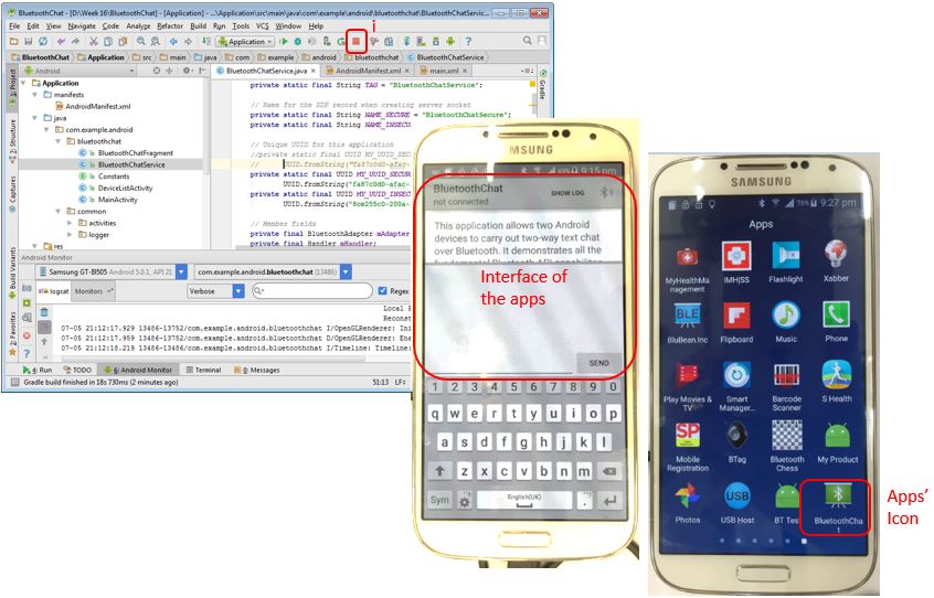
4. Upon successful installing the apps into the mobilephone, Click 'stop' (square) on the Android Studio to stop running the application>>On the mobilephone, the apps will be launched and user may see the interface. When you close the apps, the apps' icon shall appear as 'BluetoothChat'.
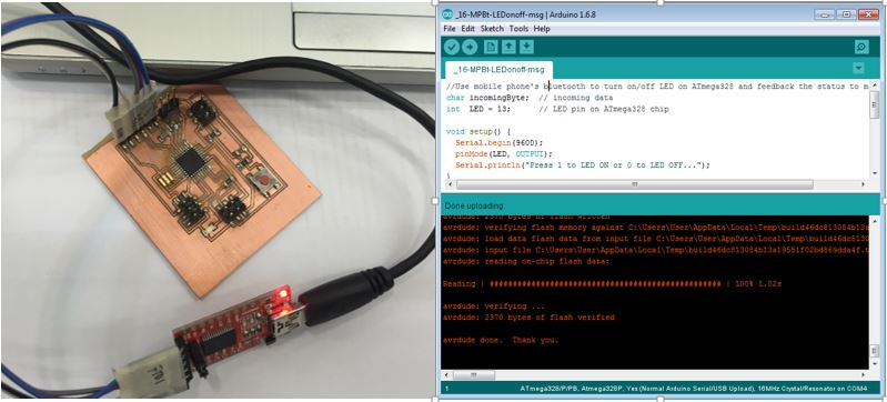
5. To set up the Arduino sketch program.
This task demonstrates the application on smartphone to turn on/off LED on ATmega328 chip through bluetooth. The following is the program loaded into ATmega328 chip through Arduino IDE - FTDI connection. The sketch is written in such a way that when '1' is received from mobile input, the LED in the micro-controller will turn ON, and the message 'LED is ON. Press 0 to OFF LED!' from micro-controller back to mobilephone. When the input from mobilephone is '0', the LED will turn OFF and the message 'LED is OFF. Press 1 to ON LED!' is sent back to mobilephone.
char incomingByte;  // incoming data
int  LED = 13;      // LED pin on ATmega328 chip

void setup() {
  Serial.begin(9600);
  pinMode(LED, OUTPUT);
  Serial.println("Press 1 to LED ON or 0 to LED OFF...");
}

void loop() {
  if (Serial.available() > 0) {  // if the data from phone came
    incomingByte = Serial.read(); // read the byte
    if(incomingByte == '0') {
       digitalWrite(LED, LOW);  // if 0, turn off LED
       Serial.println("     LED is OFF. Press 1 to ON LED!");  // print message on the phone
    }
    if(incomingByte == '1') {
       digitalWrite(LED, HIGH); // if 1, turn on LED
       Serial.println("     LED is ON. Press 0 to OFF LED!");  // print message on the phone
    }
  }
}
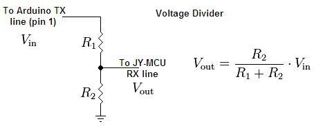
2 resistor rated at 1k Ohm and 2k Ohm are needed to be connected according to the diagram below (source: http://42bots.com/tutorials/how-to-connect-arduino-uno-to-android-phone-via-bluetooth/).
Breadboard will be used for this setup and the full connection is shown below.
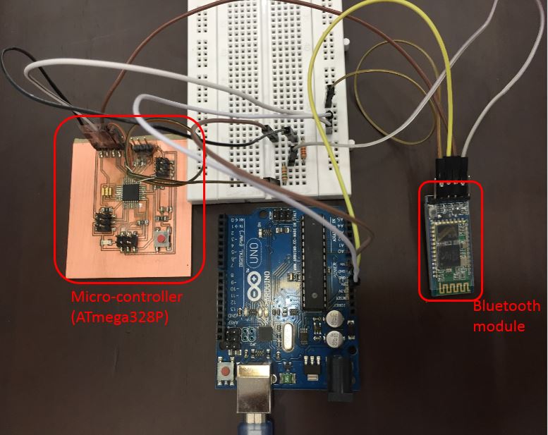
The summary of the microcontroller's pins connection to bluetooth's pins.
| ATmega328P | Bluetooth module |
|---|---|
| GND | GND |
| VCC | VCC |
| RX(0) | TXD |
| TX(1) | RXD |
N.B. The Arduino UNO will only be used to supply voltage to both ATmega328P and Bluetooth module.
Result