Router
25 Feb
Week6 Electronics Design; Eagle; Datasheet
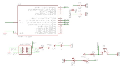
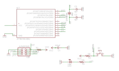
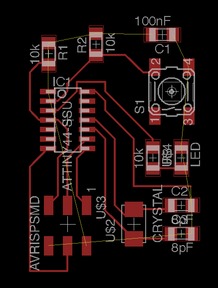
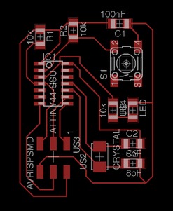
Draw a schematic design by adding components from the library. First skim through the datasheet of the AtTiny44 and figure out what each pin does. To get a rough idea of an overall arrangement, figure out pins for data transfer as well as VCCs and GNDs from each components. Then rotate the component when necessary. Here, for example, I laid all component with VCC on the left and GND on the right.
Assign pins to the board aiming at generating the neatest route to cut on the PCB board. Connect wires between each two components setting the wire thickness to 0.01.
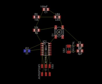
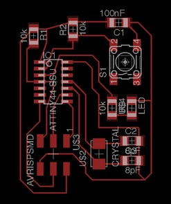
Rearrange the relative position to make the layout of the PCB more compact.
Connect all VCCs and GNDs.
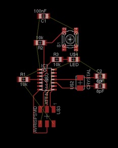
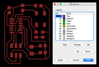
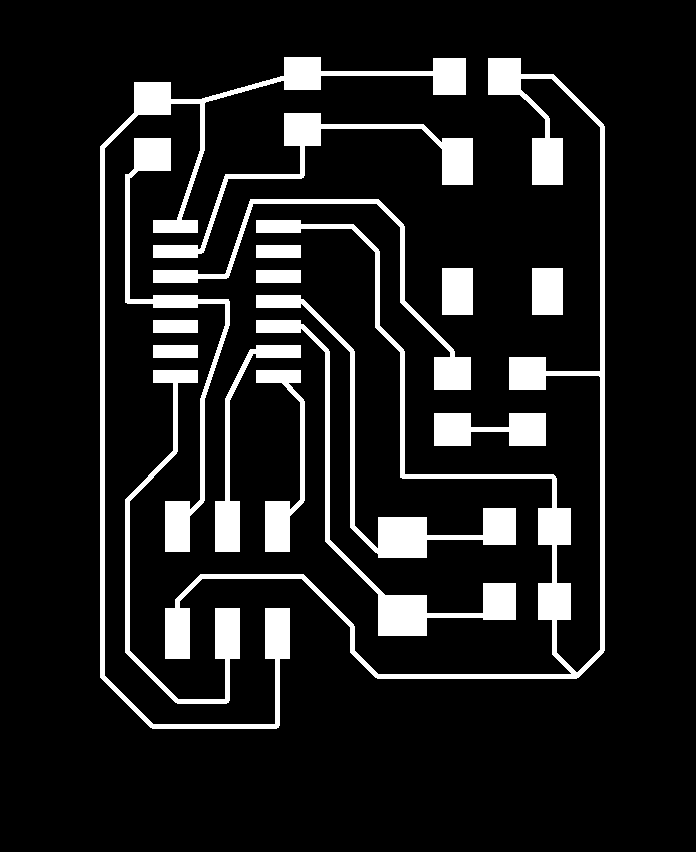
Resize the board, select to display the top layer only, then export as PNG file. Set the resolution to 500 psi and adopt monochrome mode to get a black and white picture. Leave adequate space on each side in order to draw a cut line later in Ai.
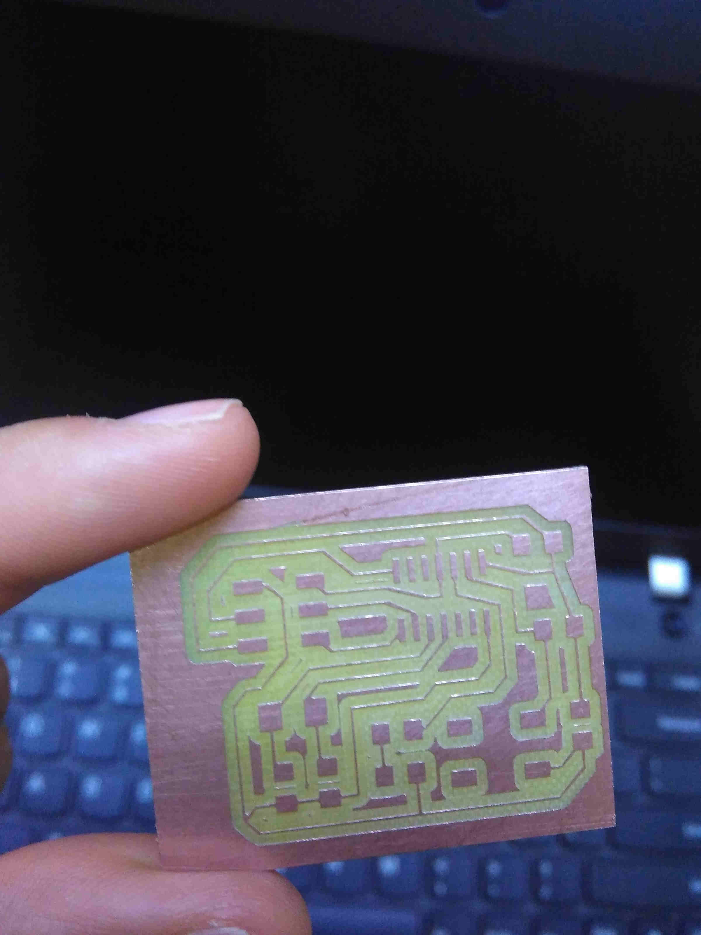
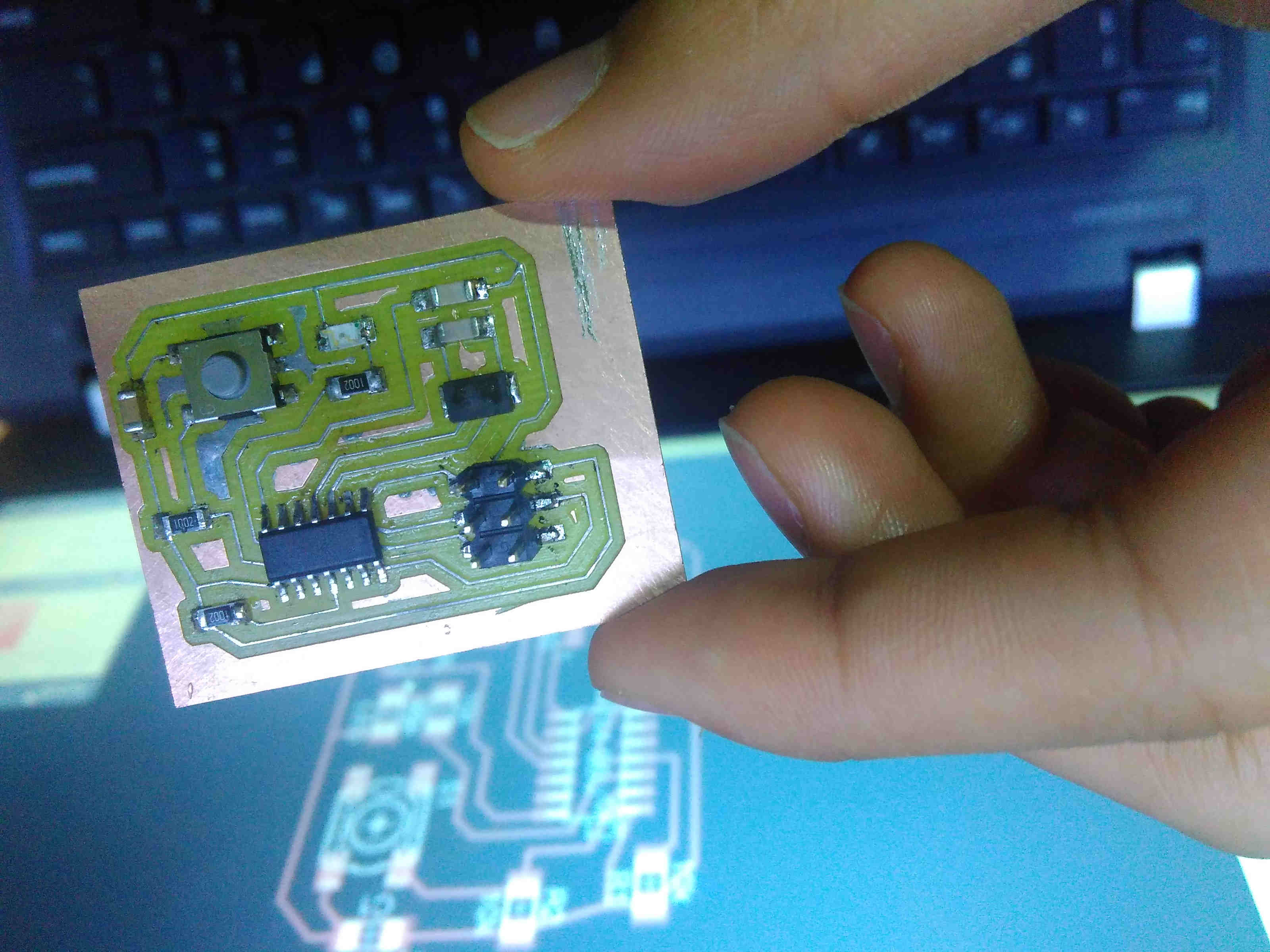
Soldering
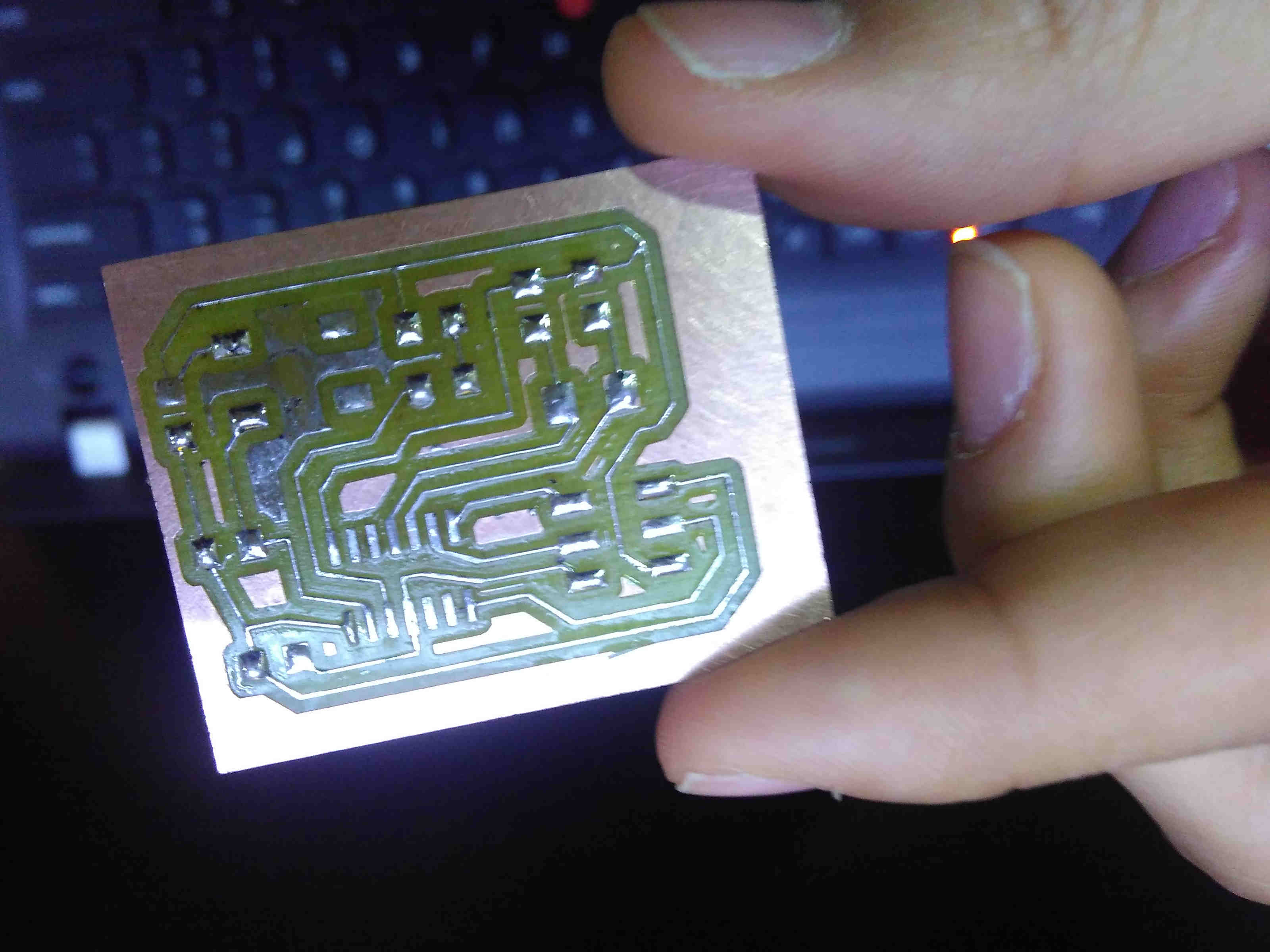
☞ Problems and Tips
Bear in mind of the limit that the milling machine can do. There are places in the original design that were too narrow for the milling machine to cut. Do tweak the line using different tools (straight, curved, tilted etcs.) when drawing.
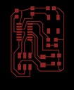
Download the cut file:
The design file in Eagle can be found here: