Output As Servo
1 June
Week13 Output Device; Servo
Using the board I made in the week of input device, this week I connected it to a servo. The datasheet for AtTiny45 helped me to find the GND, VCC, and pins to send signals/data.
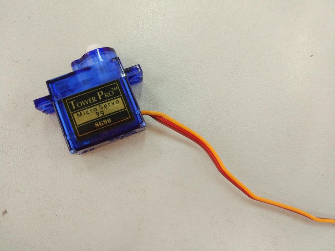
In the very first attempt to program a servo, I mostly referred to the code from metkku.net. It basically asks the servo to move to three fixed positions. In the code file, I first defined the pin and button, set the clock speed to 1MHz, and define three positions of the servo. The positions were predefined by values as it wrotes in c codes. The code "OCR0A = SERVO_CENTER" means the servo starts in the center position as defined. In this code, a global interrupt was enabled by sei command.
The code file can be viewed here: hello_servo.c hello_servo.make
Also there are libraries for AVR microcontrollers that allow users to drive servo motors like the way they do in Arduino. One of the library is called "Servo8bit". This makes coding to control the servo a lot easier and more intuitive.
The logic to drive the servo is to activate the pin by making it POSITIVE when I want it to work. And then I defined to what extent it rotated by using a "int pos" directly. Basically I told the servo to continue to move in one direction as long as the position I defined is smaller than 150 degrees. (note that the larges angle this servo can go is 180 degrees.) The code could be written in this way:
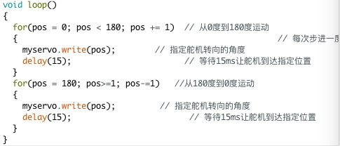
This video shows how the servo functions:Servo.mp4
And another code including controlling this servo can be found in my final project:TeaBrewer.rtf
Output As Heating Pad
1 June
Week13 Output Device; Heater
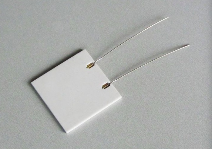
I bought a ceramic heating pad from Taobao in order to get a heater with higher efficiency for my final project. The type I bought was 12 v with 20 Ohm's reistance. The working temperature can go up till 130 degrees of which the range fitted my expectation for my final project.
One thing to pay attention to is that the MCU board is not powerful enough to provide enough power to the heating pad for it to heat up til 80 degrees. Therefore I used an external power supply with a mosfet module. Thus the MCU is directly controlling the mosfet so as to control the heating pad.
I refered to the datasheet of the MOSFET driver module I was using to figure out which pin should connect to which on the MCU and which pair connects to the heating pad or the power supply. The final look is shown in the picture below:
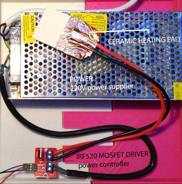
Note that here I've also changed the wire connecting the heating pad and coated a plastic tube around it in order to secure a better power supply.
To control the heating pad I only need to control the PWM, aka to set the output as HIGH or LOW. For the heating pad to heat up, I only need to add a delay after the output was set HIGH. I referred to the code that people used to control the brightness of LEDs.
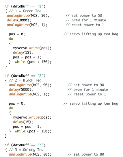
In my final project, I defined the power by providing different numbers to the pin connecting to the mosfet. After a couple of tests during my final weeks using the thermistor I made in the week of input device, I assigned 50, 90, and 80 to green tea, black tea, and oolong tea respectively when it falls into any one of these three occassions.
☞ Tips
The power supply is 220V therefore take extra care when using it. Make sure to have enough protection around including the tap. And do not do the experiment on a messy makers' desk.