This week's assignment
- Redraw the echo hello-world board
- Add (at least) a button and LED (with current-limiting resistor)
- Check the design rules, and make it
- Extra credit: simulate its operation
Drawing the board
Basics
There are 2 different connector; ISP and FTDI. We cannot upload(bootload) first progeamme with ftdi. We already made a ISP previous week. So we gonna make echo hello board with ftdi. (echo means the borad do something repeatly)
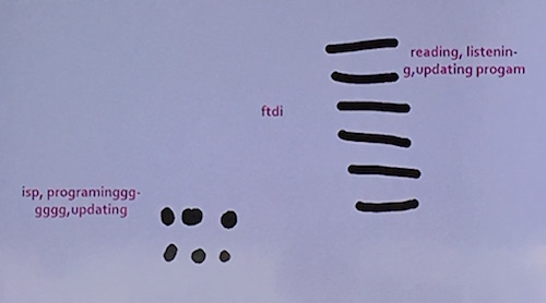 ISP is better but more difficult while FTDI is easy bt less powerful
LED needs to be connected with resistor. Different colour led has different power consumption. We need to check the datasheet for matiching resistors. And calculate it. Here's useful link.
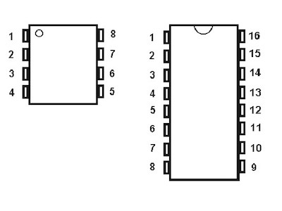
IC chips ports number rules
Eagle
Follow the tuorial
Let's start PCB making using Eagle!
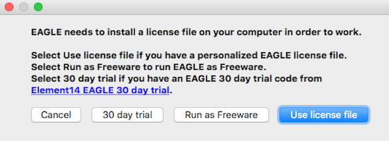
- Download Eagle and run as a Freeware.
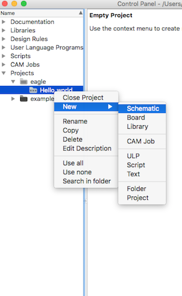
- Make a new project
- Add a new schematic in the project
- Download library and add it. download fab library here. In case of you using Mac OS, put the library /Applications/EAGLE/lbr/
- Add components: Find componects in libraries
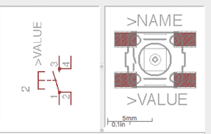
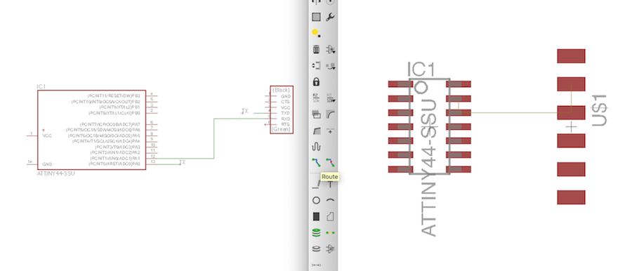
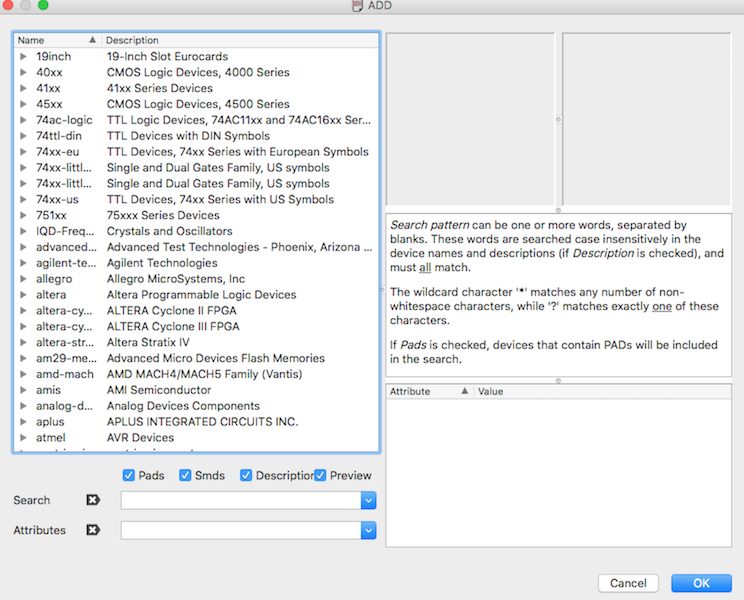 Use search bar. When you find the componects you can see two images. First one is the symbol of the componect: it represents the components on schematic. And the second one illustrates how it looks like in layout. Anyways both present the same components. Check the datasheet and make sure that the component in library is same with the model you'll use in real.
- Place the components and wire them:
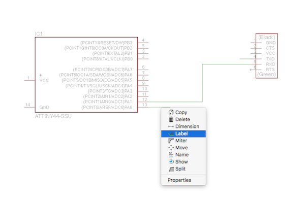 You can just directly wire them or using label. Labelling is is useful when schematic is complex.
 - Check the layout
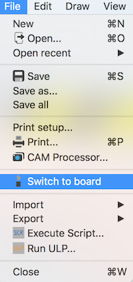 Find the icon on bar or click File -> Switch to board.
Then you can see the layout on board. Thin line guides which parts should be connected. Click 'Route' and we will connect them. Note: connection in layout means the physical connection. It represent the actuall look of the circuit board we'll get later.
Find the icon on bar or click File -> Switch to board.
Then you can see the layout on board. Thin line guides which parts should be connected. Click 'Route' and we will connect them. Note: connection in layout means the physical connection. It represent the actuall look of the circuit board we'll get later.
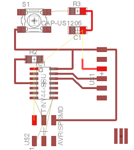
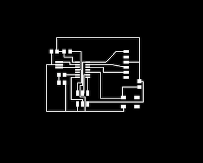
- Layout design
 help me...!
If you make routes after you wire, you can see all guide lines in layout window. When you click any parts, Eagle shows where is should be connected.Important tip: Layout will be quite complicate if you start connecting route after finishing all wires. I was even not sure where to start it. Also spent so much time on changing layout design.
help me...!
If you make routes after you wire, you can see all guide lines in layout window. When you click any parts, Eagle shows where is should be connected.Important tip: Layout will be quite complicate if you start connecting route after finishing all wires. I was even not sure where to start it. Also spent so much time on changing layout design.
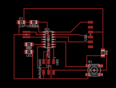
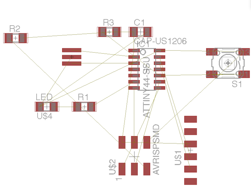 So it is recommended that schematic and layout design go together. Otherwise you will find that some components are trapped inside.
 - When everything is connected correctly, export it.
**Some notes on Eagle
- change the grid system helps you more precise design
- Thinner route size also helpful
- Unroute! Deleting route in layout without changing schematic. I didn't know how to delete the route I made.
Useful Links:
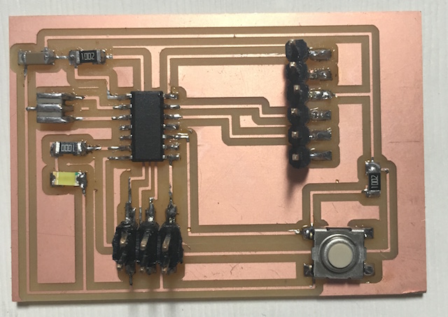
Results

Design Files
downloadConclusion
What I succeeded
- Use Eagle
- Redesign the echo hello-world board
- Add a button and LED
What I didn't do yet
- Check the operation of the board
| ← week5 | 3d scanning and printing | week7 | computer-controlled machining → |
|---|