This week, I wanted to make wireless network connection between processors and control them wirelessly. The goals are
- Understanding wireless network
- Using BLE(Bluetooth Low Energy)
- Adding Wifi connection to porecessors
Wireless Network
Goals
This week, I mada plan to build LED lights connected and can be contrlled wirelessly. First thing came up to my mind was using a ble(bluetooth low energy/bluetooth 4.0). I did some research on archive and found some good documents.
So what I planned to make constists of one master module and two slave modules. The master module is connected to internet and controlled by mobile through Wifi and the slave modules are controlled by the master over the ble connection.
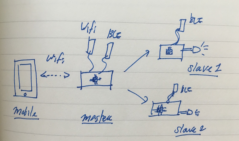 concept
Bluetooth Low Energy
Introduction
Bluetooth low energy (Bluetooth LE, BLE) is a wireless protocol. Compared to Classic Bluetooth, it has considerably low power consumpotion.
HM-10 is the most widely used ble module. It is a breakout board with cc2541 chip. More detailed information, check this datasheet. All AT commands(we'll discuss about it soon) are specified in datasheet, so it is highly recommended to read it.
AT Commands
The most important thing for using a bluetooth is knowing a AT commands. When using a ble module, the first thing you do for setting is connectig module with FTDI.
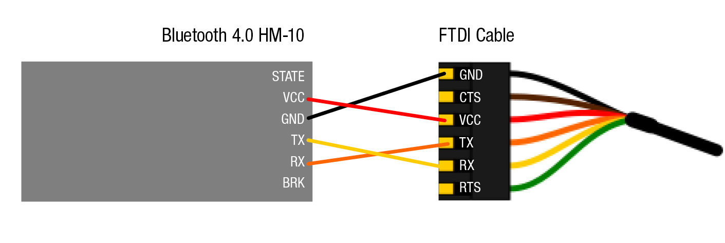 image courtesy by Dan Chen
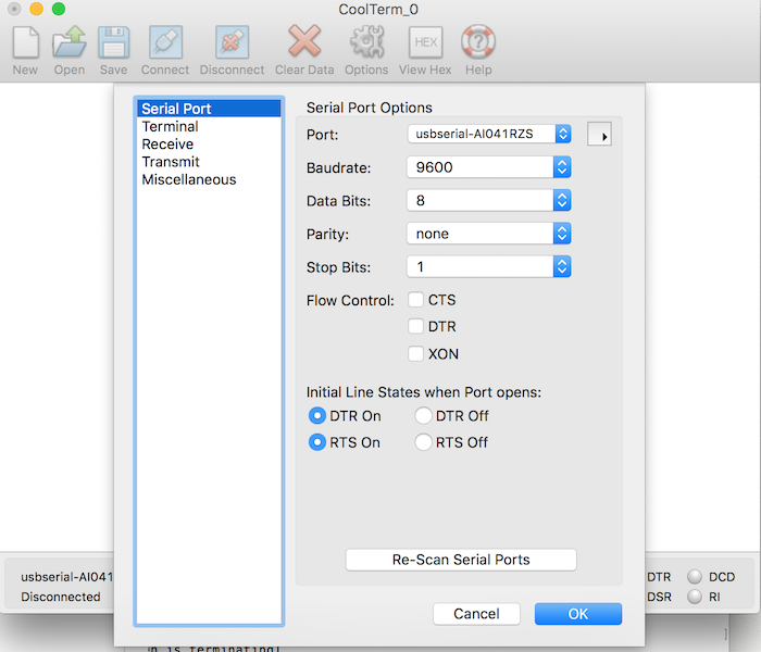
You can just use Arduino IDE for Serial communication, but I used software called coolTerm. When BLE is connect to your laptop with FTDI, you can send it AT command with this software to modify the settigns. Make sure that Baudrate is 9600(default setting), 8 Data Bits and 1 stop bits.
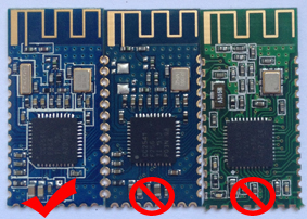
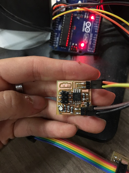
After spend some time on connecting ble modules, I found out it is not an authentic HM-10. All of my ble modules are BLE CC41A and it is the clone board of HM-10. You can easily check by outlook. BLE CC41A is missing crystal in the corner bleow the antenna.
The bad thing of BLE clone is that it has different AT commands. I spend most of my time on struggling with AT commands and here are useful links. Differences between HM-10 and CC41A. BLE clone board. ARduino forum.
Here is the datasheet of the CC41A. Following lists are what I found usefull.
- AT : Checking the connection
- AT+VERSION : Checking the version
- AT+HELP : Lists of AT commands
- AT+NAME : Checking the name of the module. BT05 is the default name.
- AT+NAMEshim --> +NAME = shim : Setting the name. Here I set is as 'shim'.
- AT+ROLE : ROLE of the module. ROLE = 0 is the slave and 1 is master.
- AT+ADDR : MAC address.
- AT+INQ : Search near devices with their numbers.
- AT+CONNn : Connecting the device 'n'(n should be a device number who want to connect. For example, if you want to connect to device number number 2, type AT+CONN2.
And here, what I still have no idea about.
- How can I disconnect the slave module without turning it off.
- How can I connect the device diretly with using MAC address. Because the device number changes everytime I turn off the modules.
- How can I actually transmit the data??? How can I convey the data in the signal?
Communication Test
Before I build my own board, I tested it with arduino. After you set up the ble module, you can easily connect it with your bluetooth device such as your mobile. To scan ble module, I used LightBlue. When you power up ble module, it will be shown as it set.
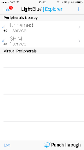
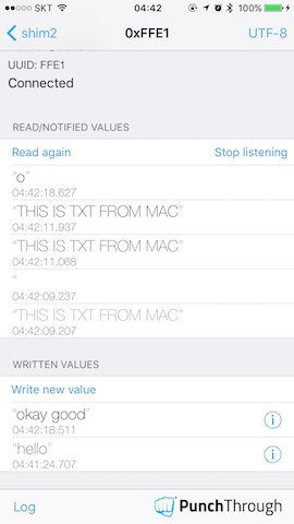
When the ble is connected, it stops blinking and the light goes solid. I played around with sending and receiving data through ble. Either HEX or String could be sent and received.
So ble serario is like this
- Master sends a data to Slave.
- According to the data the Slave received, RGB LED light on Slave module turned on.
So the rgb led attached on slvae board will change colour. For instance, if the master send 'b', the led would be blue.
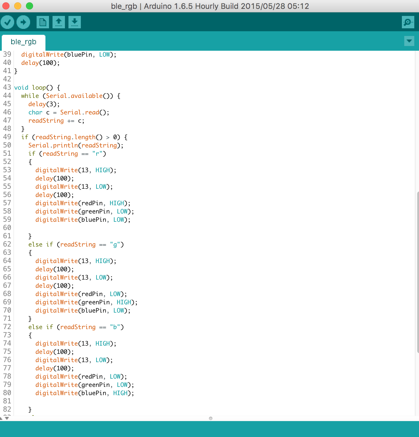 Test code
Board Design
First, I made the slave module with hello.RGB.45 board. And it works fine! So I modified it little bit by change the processor from Attiny 45 to Attiny 85. To use TXD/RXD serial, we can use SoftwareSerial liberary. Here is nice link. Also this and this
Attiny 85 has 4 I/O pins(datasheet. I used PB0, PB1, PB2 for controlling rgb LED and PB3and PB4 for RXD/TXD.
Design Files
downloadConclusion
What I succeeded
- Using ble module
- Sending a data packet over ble protocol
- Controlling LED lights wirelessly
What I didn't do yet
- Connecting processors wirelessly
- Adding wifi connection to the processor
What I leanrt
- DO NOT BUT A BLE CLONE! It has limited feature and gonna waste both of your time and money.
| ← week15 | composite | week17 | interface and application programming → |
|---|