
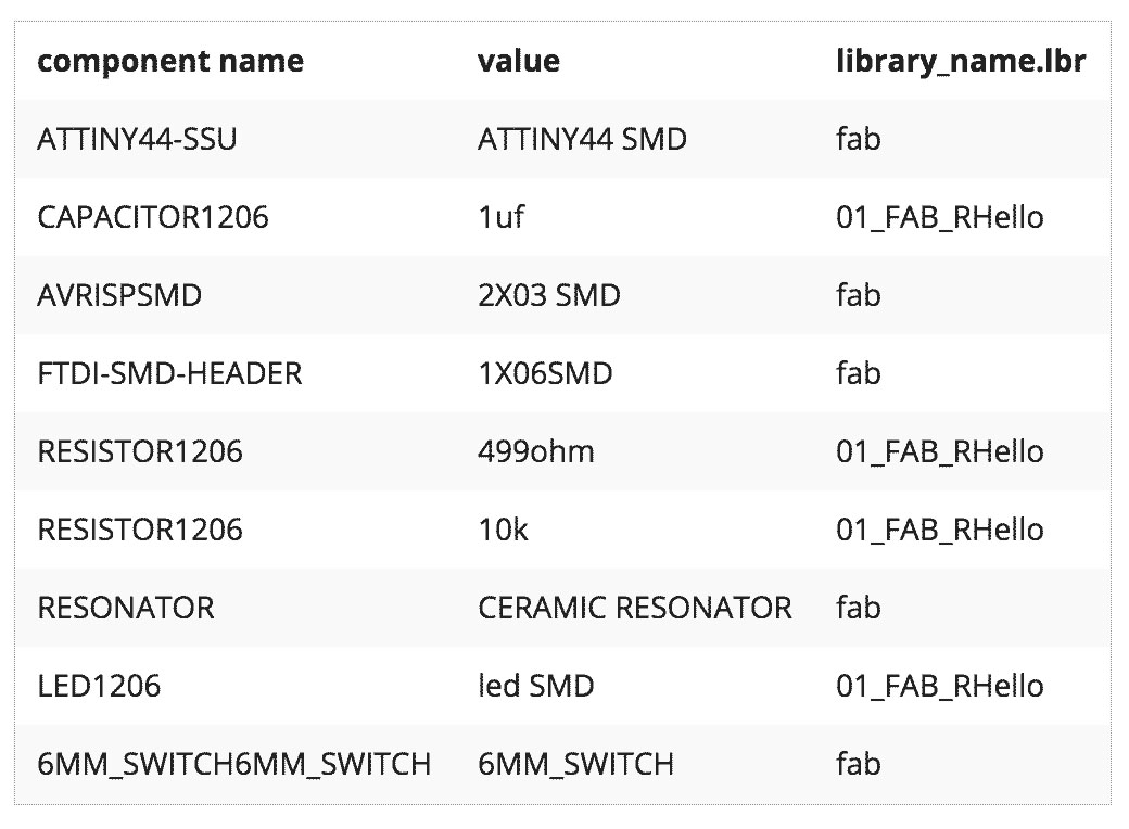
Electronics Design
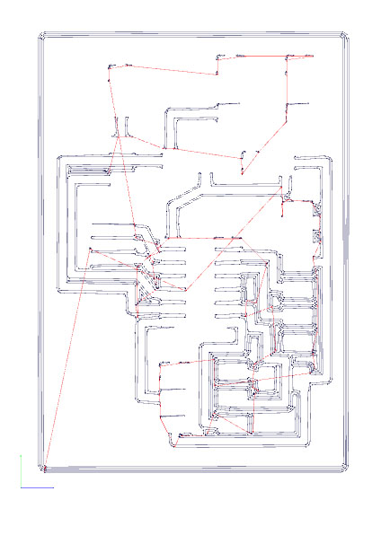
I start with this image, after loading the fab lib, I "add" the components in the workspace, and then with the "net", "name", and "label" I connect all the components based on this picture.
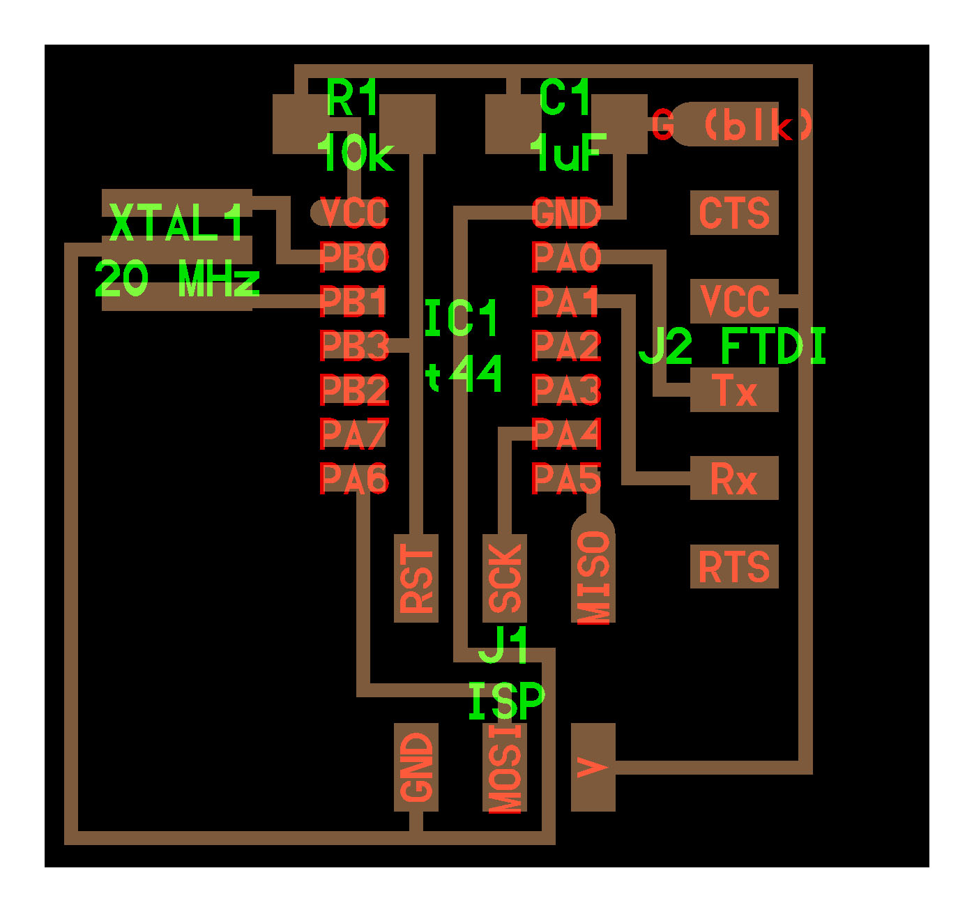
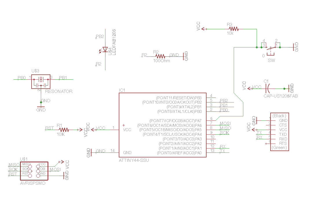
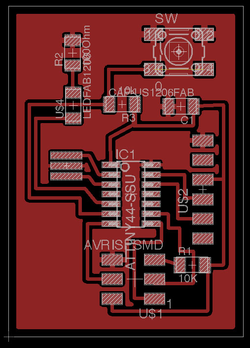
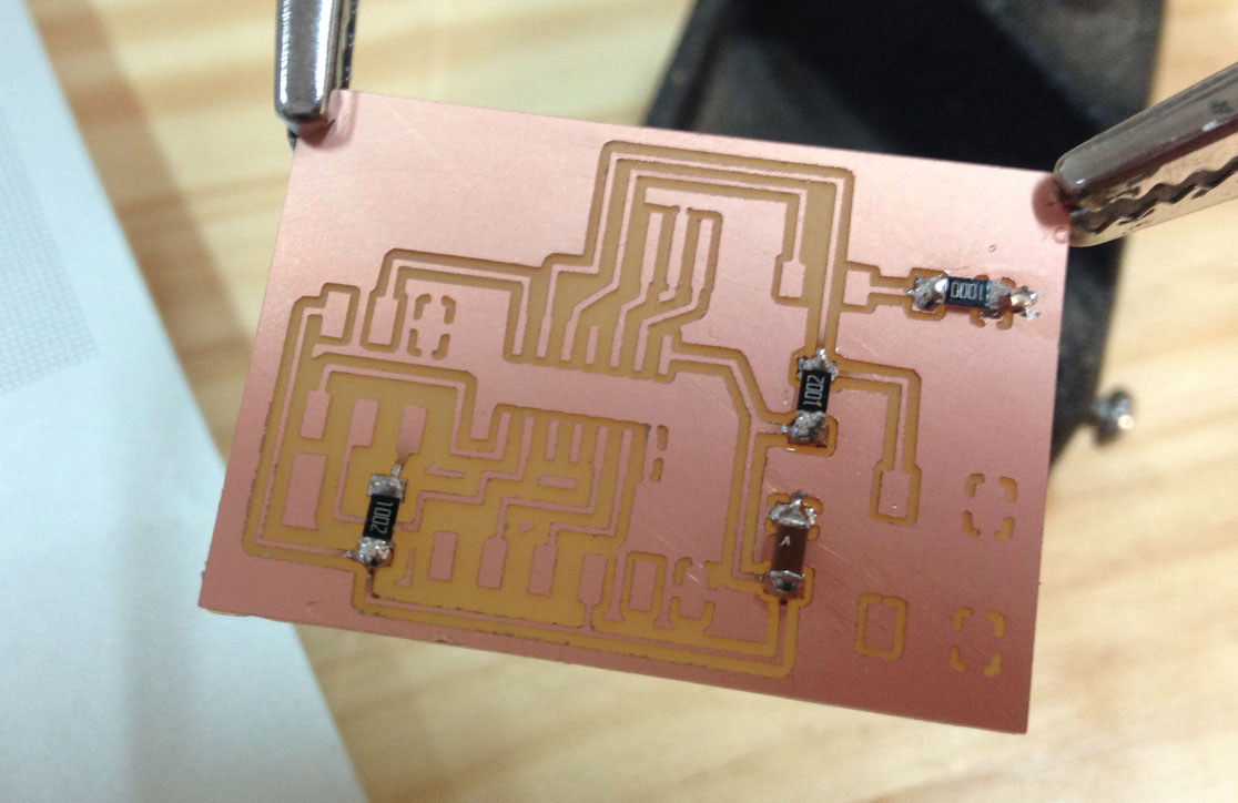
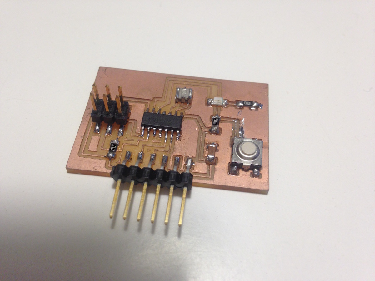
Then I added a button with a pull-up resistor to the PA7 pin, and the led with a 100-ohm resistor to the PB2 pin.
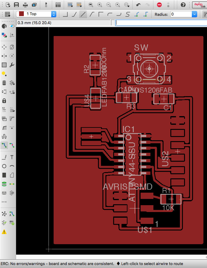
Design the board in Eagle
Download design files in Eagle format
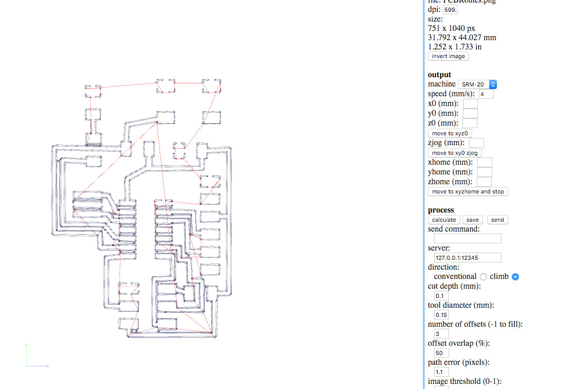
I have to set the tool diameter for the traces in 0.15 mm.
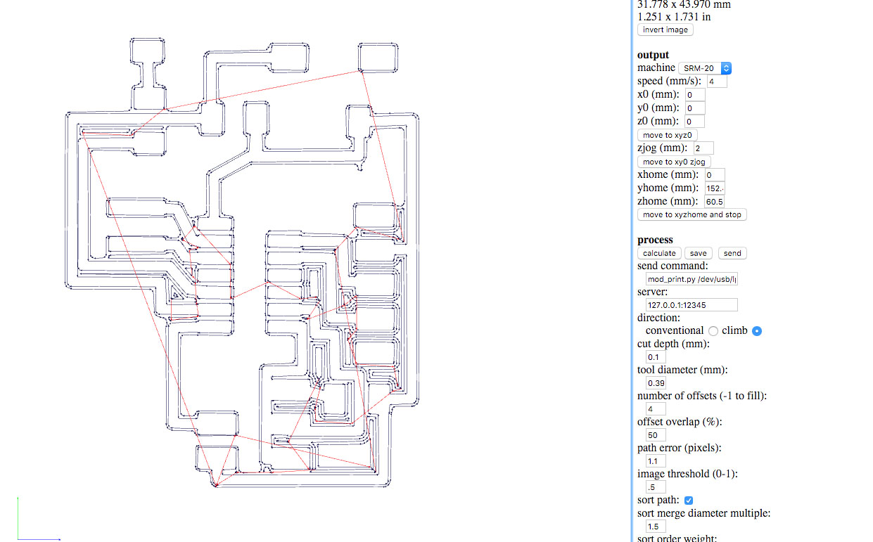
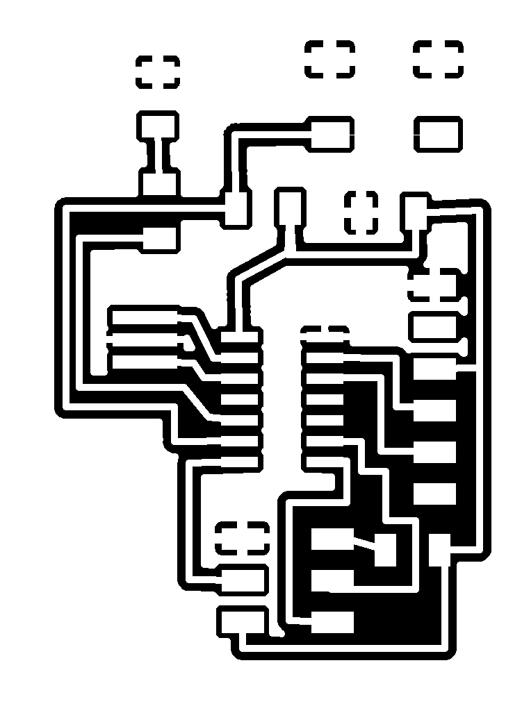
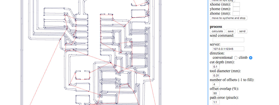
Inverted image in Fab Modules
Changing tool diameter in Fab Modules
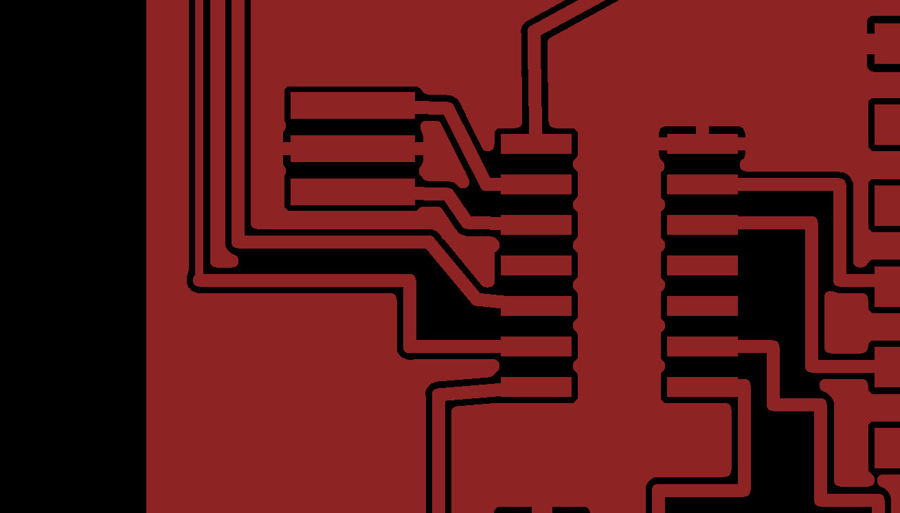
Some of the GND pins doesn´t appear in the traces.

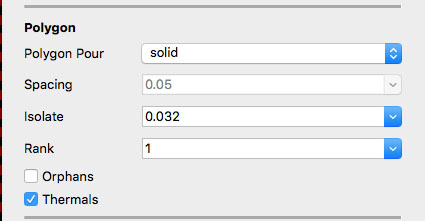
Trying to get correct milling traces, I try the isolate comand in the info menu.


Design Rules
Finaly I understand why design rules are so important.
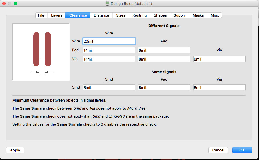
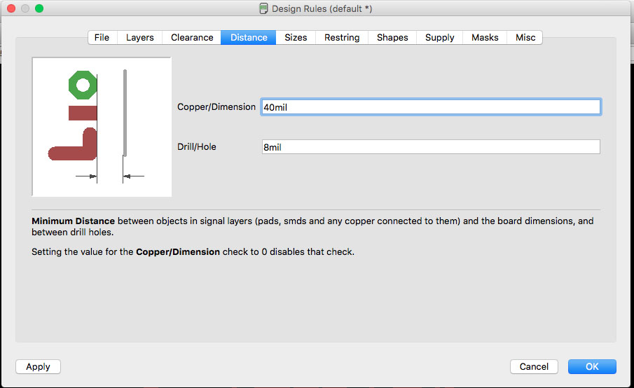
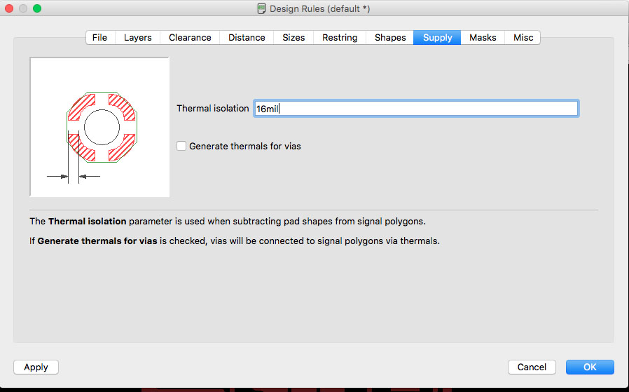
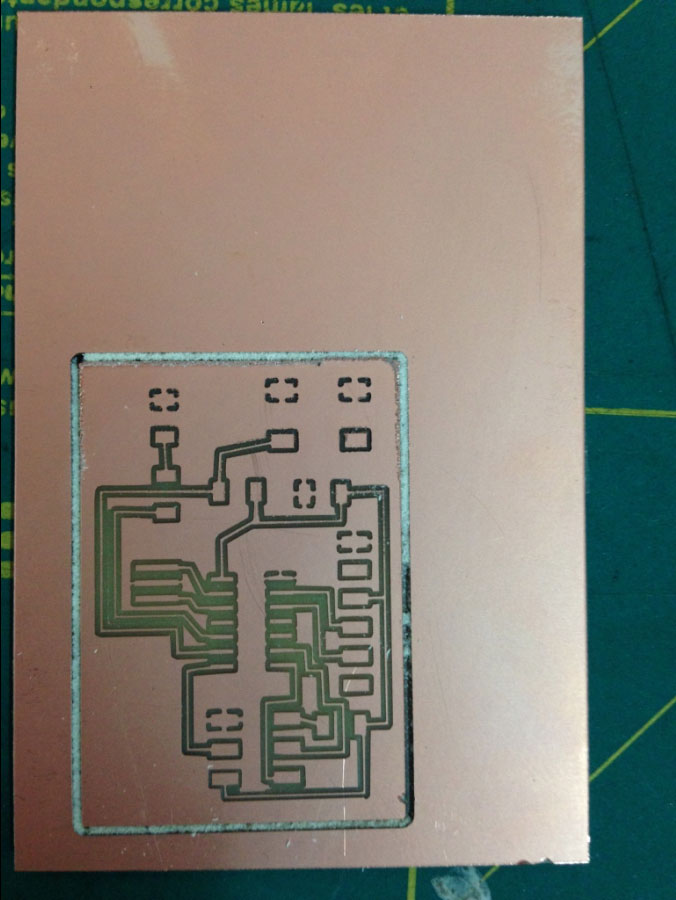
With new values in the design rules I export a better PCB design.
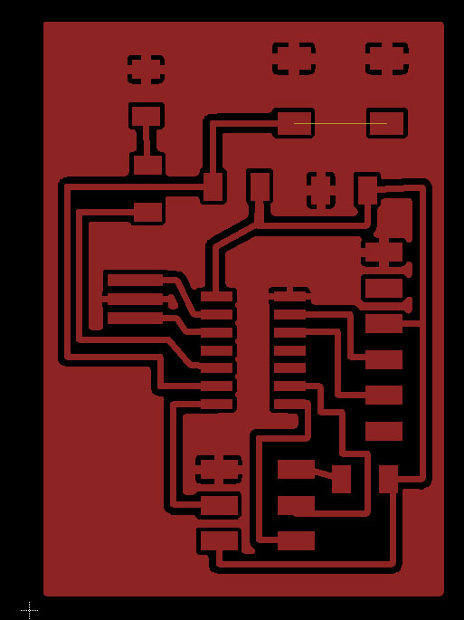

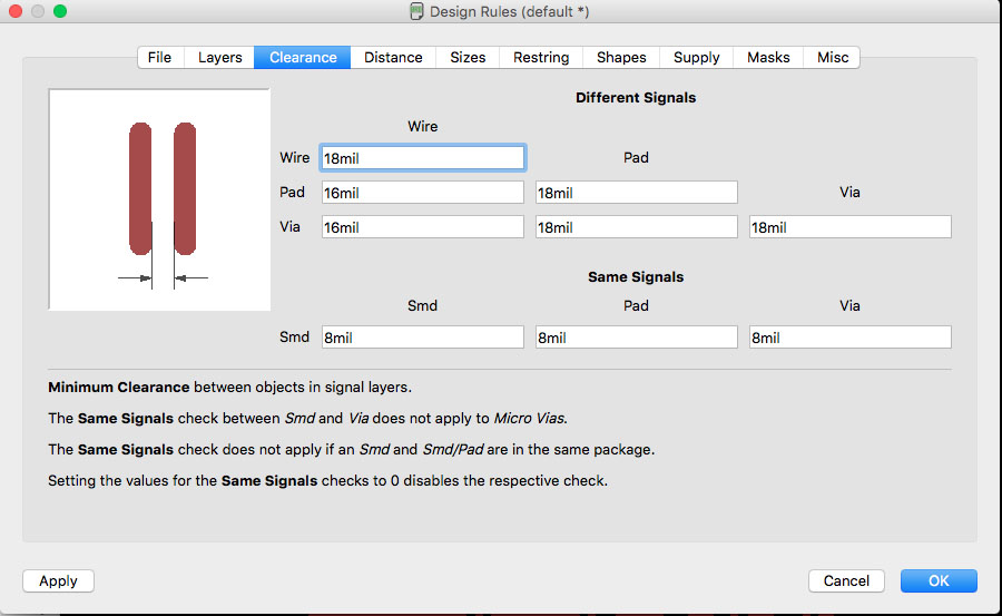
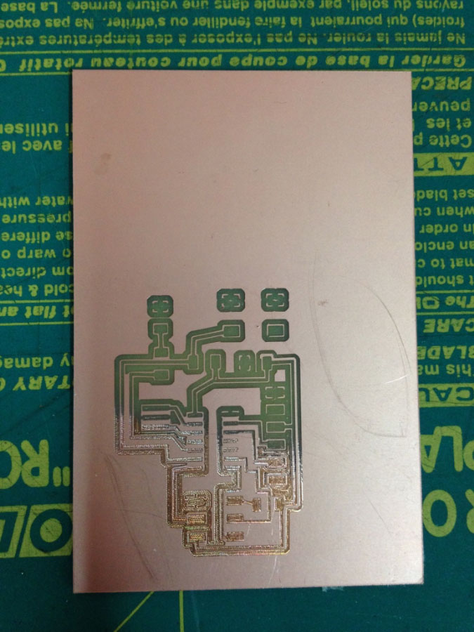
I tweak the wire size to 18mil in order to get better traces witouth changing to much the mill size in Fabmodules.
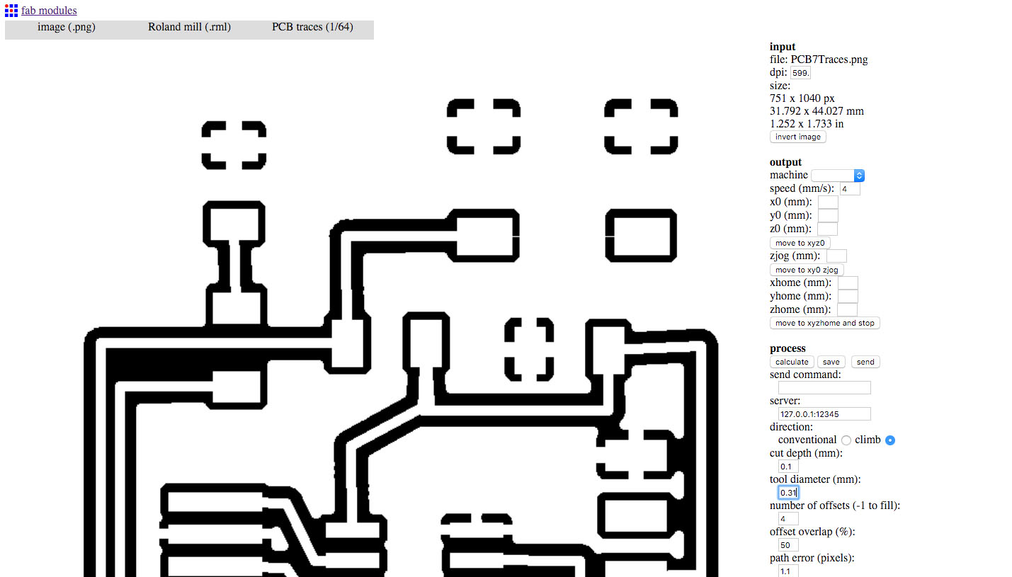
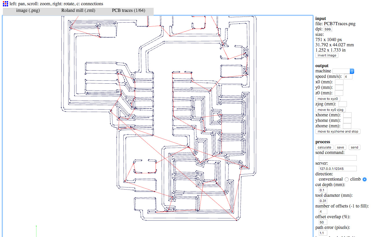
Finally, the PCB looks great in FabModules with a 0.31 mm tool diameter.
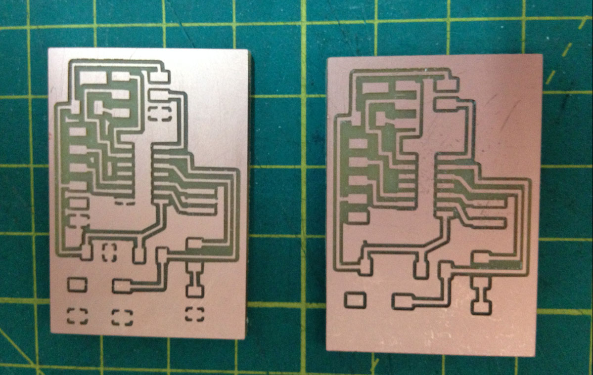
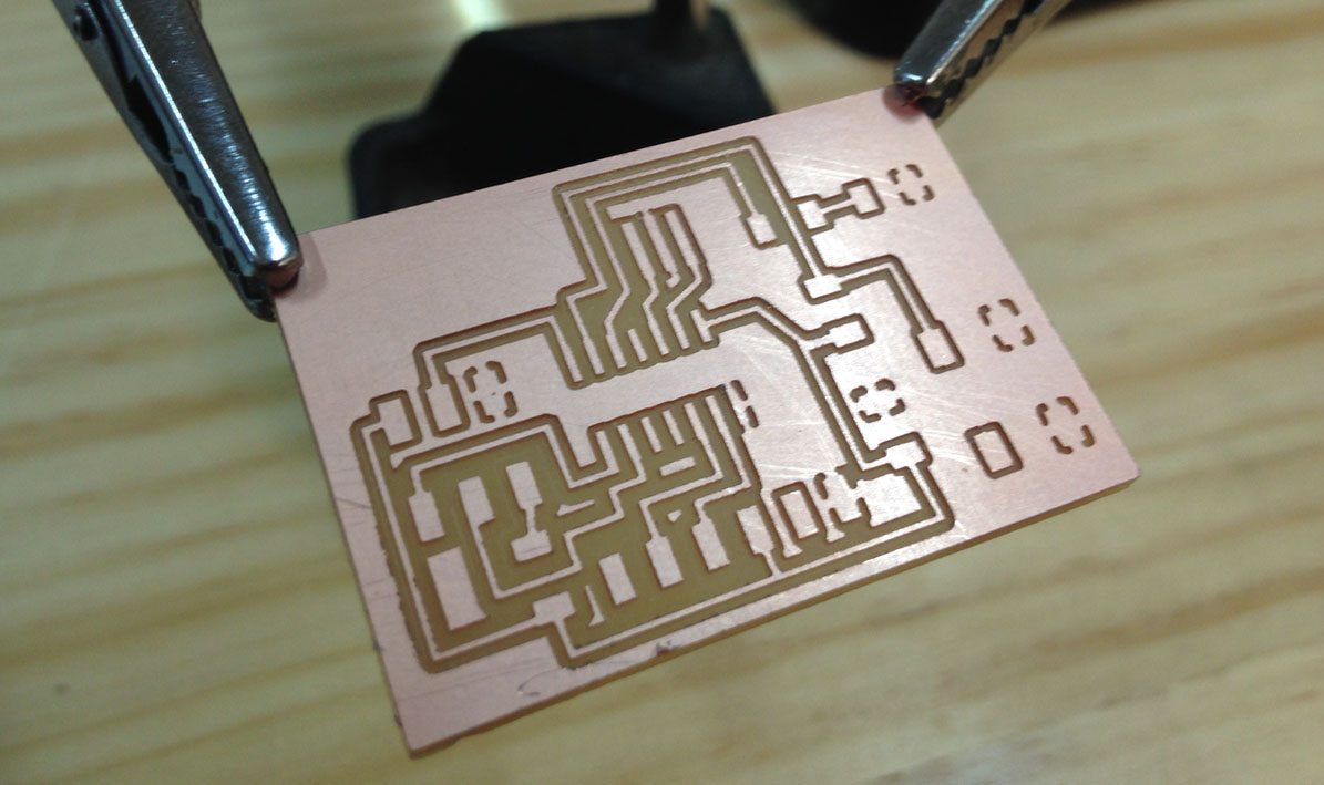
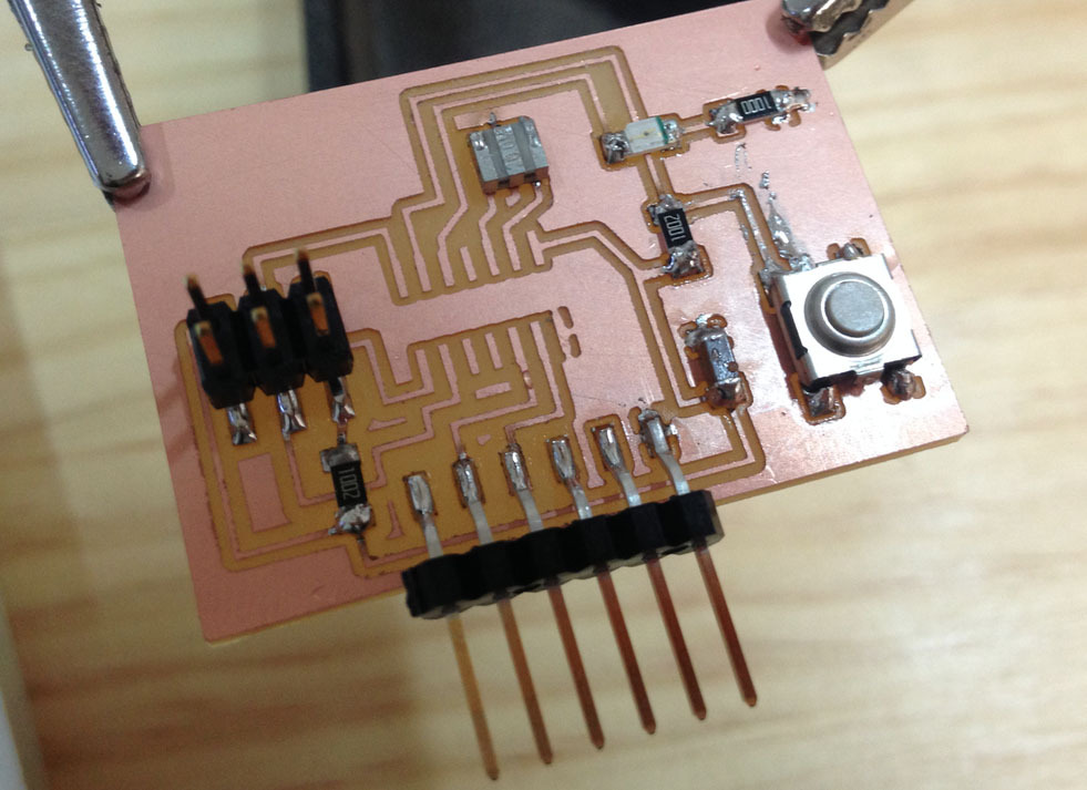
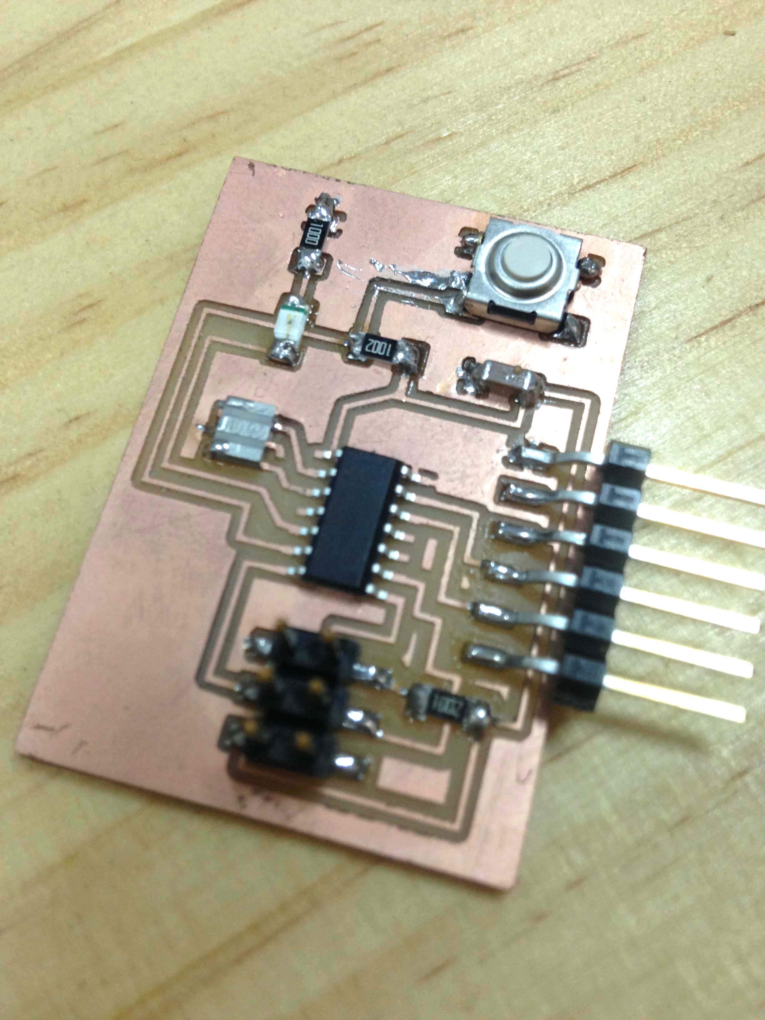
Soldering
Work info:
References: Class Page, fab modules,
Assignment
redraw the echo hello-world board, add (at least) a button and LED (with current-limiting resistor) check the design rules, and make it extra credit: simulate its operation extra credit: measure its operation