Edward Octavio Muñoz Sandoval Contact: edw_ard0@hotmail.com
Week 7 Assignment: Computer-Controlled Machining
1.- Make something big.
Design
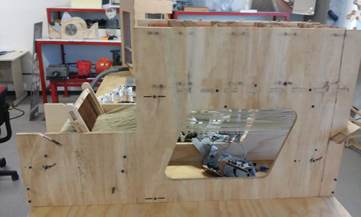
For this assignment I design a Jacquard loom structure, which is actually my final project. the parts I designed in 12mm plywood were the lateral walls, structure support, reed parts, and a support for modulus.
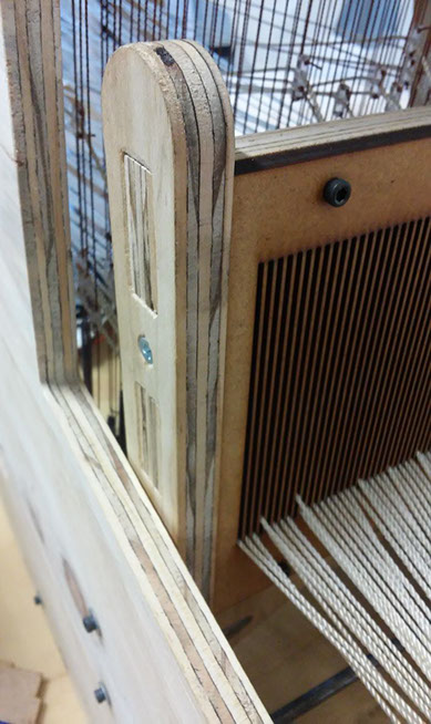
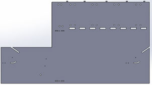
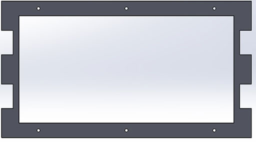
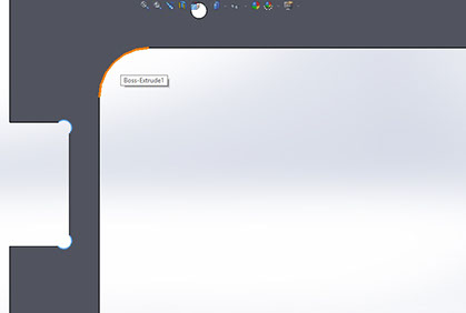
Lateral Walls
This was a difficult design because all the mechanisms and details I has to consider.
Below are some images of the design process, in my experience I highly recommend to do a base for your design and continue with the holes for everything you want to do but in separate operations. In that way you were be able to made modifications more easily than if you made a sketch with a lot of measurements and references.

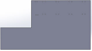

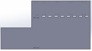
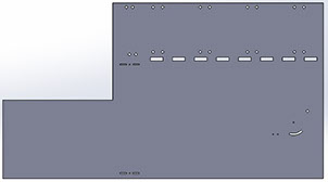
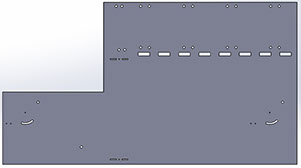
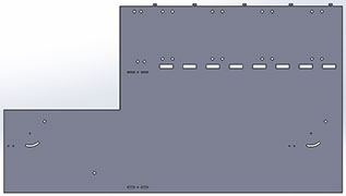
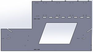
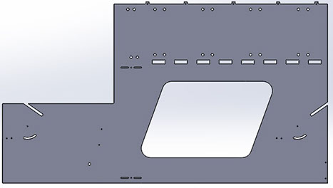
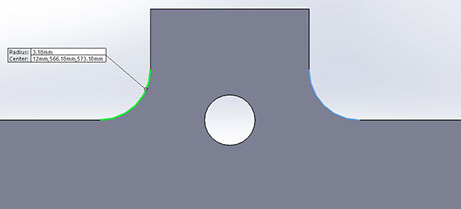
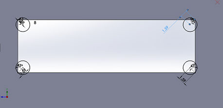
In this design I consider the dog bones and a radius of at least 3.18mm because the end mill I used is 3.175mm
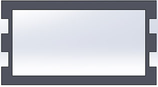
Support for modulus
This part was also designed for a 12mm plywood with an End mill of 3.175mm
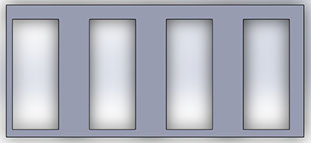
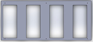
This design have dog bones and radious of 3.18mm
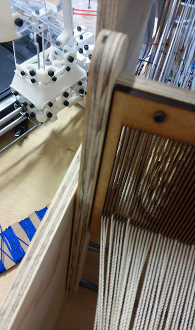
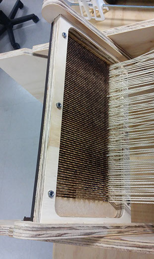
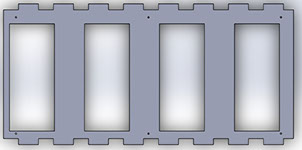
Reed parts
This design is for allow the circular movement of the reed
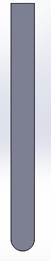
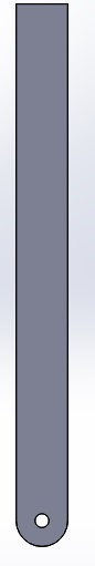

Also have dog bones

This part is designed so the reed can be mounted with screws and can be easily replaced


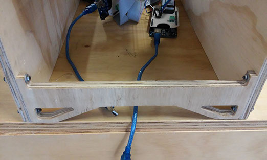
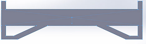
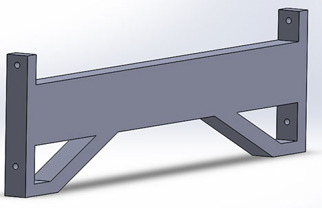
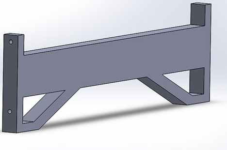
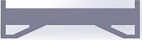
Structure supports
This piece is just for avoid stress concentration in some areas of the machine, I realized latter that it help also to straighten the playwood.
Machining
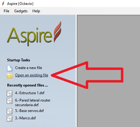
I used Asipre software to generate the path for the router.
The firs step is open a new or an existing file.
If you open an existing file it would be a .dxf extention

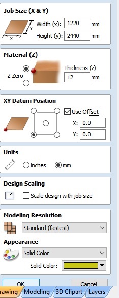
After load the file, have to define some parameters as the job size in X and Y axis (1220X2440mm, normally), the deepness (12mm in my case), the units, an scale if you want.
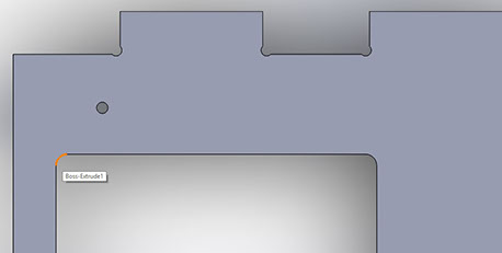
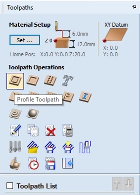
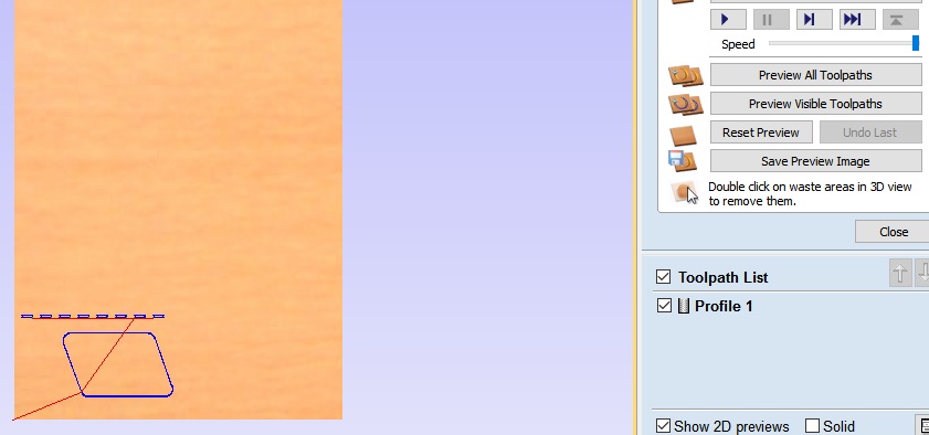
Aspire have tools for generate paths based on the design loaded previously. In my case I selected all the internal cuts (the line turns pink as shown in the image) and apply the profile toolpath.
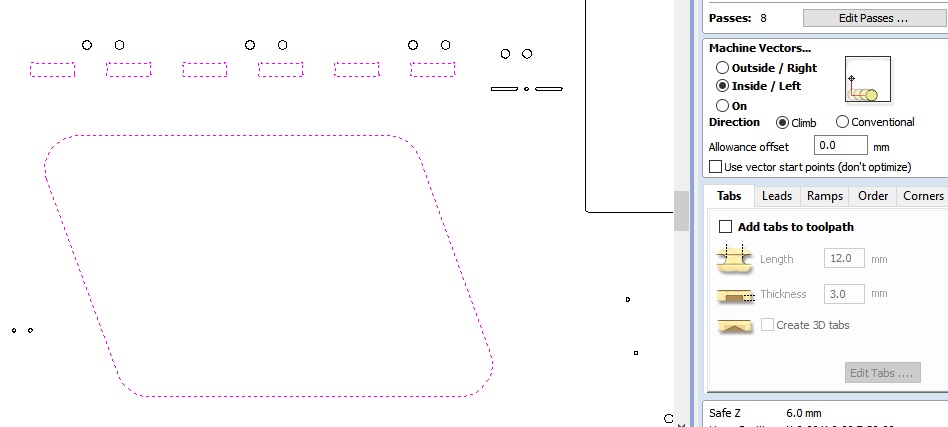
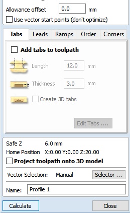
This tool "profile path" allow to cut with internal or external compensation, the starting and final depth, the number of passes, and some other features.
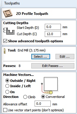
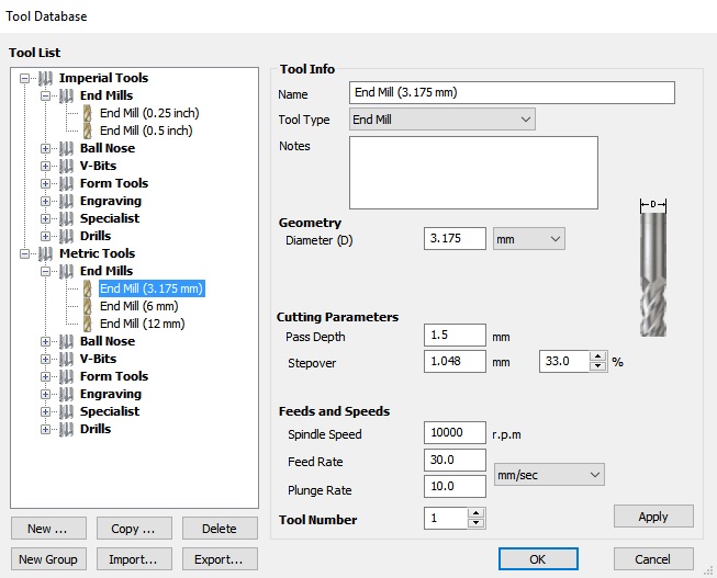
Also have to select and set the parameters for the tool to use.
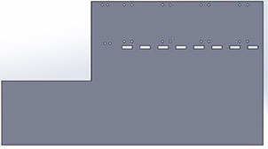
In my case this was a problem because in my first attempt using aspire to drill a 3mm hole, the path doesn't appear because the end mill have a larger diameter than the hole. So in my second attempt my logic was to change the diameter of the hole to an exactly 3.175mm, but surprisingly they still didn't appear. In my third attempt change the diameter to just 3.18mm and it work, this is important to don't waste a lot of time in future designs
Once the toolpath was generated, the user can have a 3D preview.
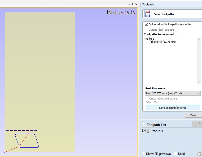
The final step is to save the toolpaths in G code so the router can run it, it´s important to consider that the G code is going to be generated in the order the toolpaths was generated, so is important do the internal toolpaths and the external at the end.
Then just remain machining, which is a very long process.
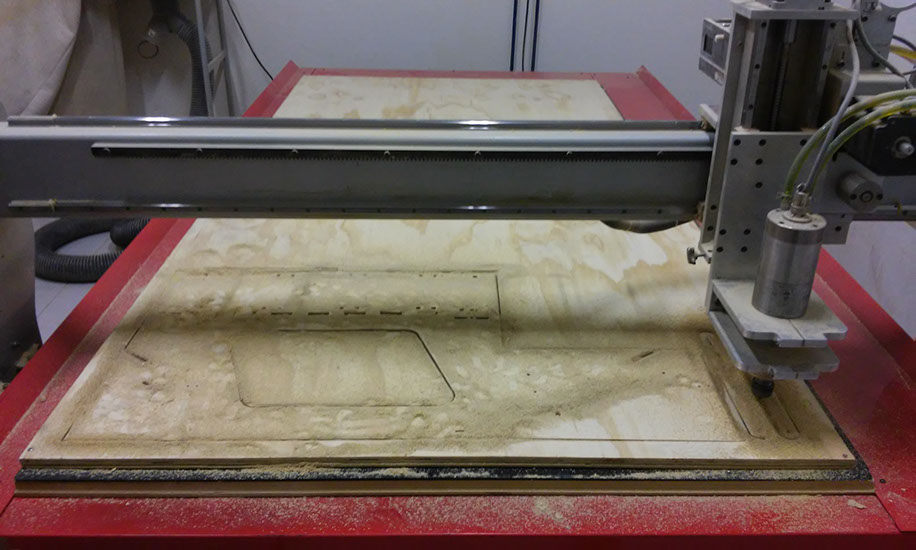
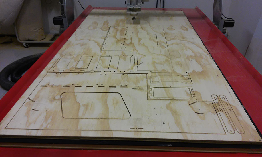
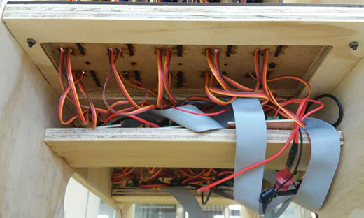
Final product