Edward Octavio Muñoz Sandoval Contact: edw_ard0@hotmail.com
Week 11 Assignment: Input Devices
1.- Measure something: add a sensor to a microcontroller board that you
have designed and read it
Electronic board used for this assigment:
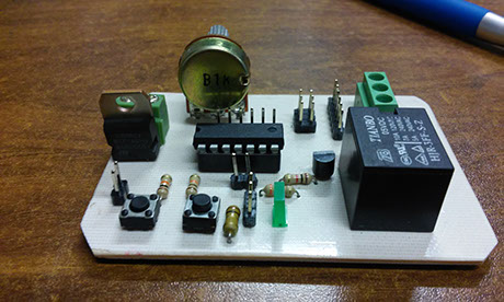
I already experimented with a digital input in the week 8 assignment, so I wanted to test an analog input with a 1K ohm potentiometer.
Before start with the code, is essential to know how a microcontroller can read an analog signal.
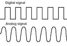
A digital signal is a signal that represents a sequence of discrete values
An analog signal is any continuous signal with infinite possible values
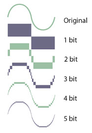
When a microcontroller receive an analog signal, it convert the voltage value into a equivalent value. In the case of the Attiny 84A match 0V with 0 and 5V with 1023, this is because it has an 8-bit ADC, in other words the microcontroller split 5V in 1023 parts giving 0.00489 V per unit, so if the voltage input is greater than 0 and lower or equal to 0.00489 V the value is 1.
If the ADC would have more than 8 bits it would split the input signal in more parts,
between less bits it would have less resolution.
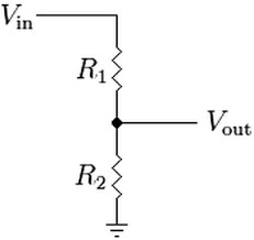
To understand how a potentiometer can generate different levels of voltages lets assume it have 2 internal resistors in one component, and we connect it like in the image (Vin, ground and Vout) with Vout as a input of the Attiny84A.
If we have this diagram, the potentiometer value (1K ohm in this case) is the sum of R1 and R2.
1K ohm =R1+R2
And the values R1 and R2 can change but always following the formula.
With this in mind and set Vin to 5V
if R1 reach 1k ohm then R2 = 0 and Vout will be 0V
if R1 reach 0 ohm then R2 = 1 K ohm and Vout will be 5V
Moving R1 along 0 and 1Kohm Vout can be set to any value between 0 and 5V
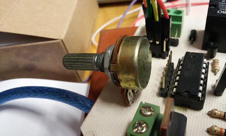
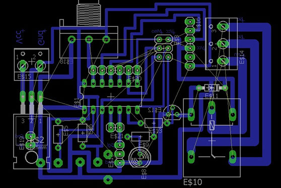
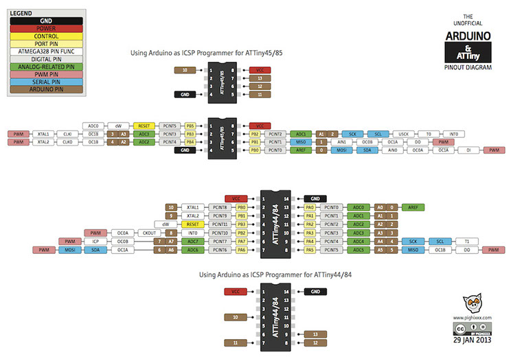
This potentiometer was already in my attiny circuit board at the 13 pin, which is the 0 programing pin based on the image:
This code turn on and off a led, based on the lecture of a potentiometer, as we know the attiny reed a binary value from 0 to 1023, depending on the voltage reed on the pin from 0 to 5 volts. This value is taken by the attiny and transform it in a delay for the led.
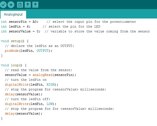
As you can see in the video, the code and the board was a totally success