Assignment 7: Computer-Controlled Machining
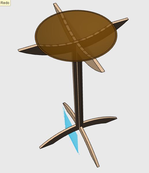
I designed a leg for the bowl I made in composite week. I used 123D
Design to create a piece, that can be connected with a another
similar one to make a leg.
Design process:
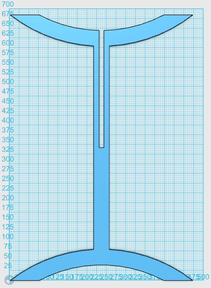
I started by creating two spheres with 340 and 380 mm radius. I
aligned the spheres and subtracted the smaller one (Source) from the
bigger one (Target) to make a ring.
I the created a box of 760 mm and aligned it with the ring, and then
moved the box 80 mm upwards. Then I subtracted the box (Source) from
the ring (Target) to make an arc. Then I copied the arc and flipped
the copy horizontally. Then I snapped the to arcs and moved them 520
mm apart to get the desired 680 mm (arbitrarily chosen) total
height. The I created a box of 520x40x12 mm and aligned it with the
two arcs now grouped together, so that they don't move
independently. The 530 mm long box overlaps with the arcs. The I
created a 600x12x12 box, aligned it with the previous solids, again
grouped together. Then I changed the length of the newest box from
600 to 300, and moved it upwards 150 mm. Now all parts were where
they should be. Then I merged all but the small box, and then
subtracted the small box from everything else.
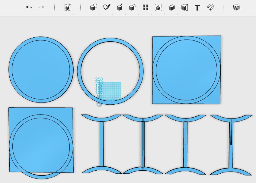
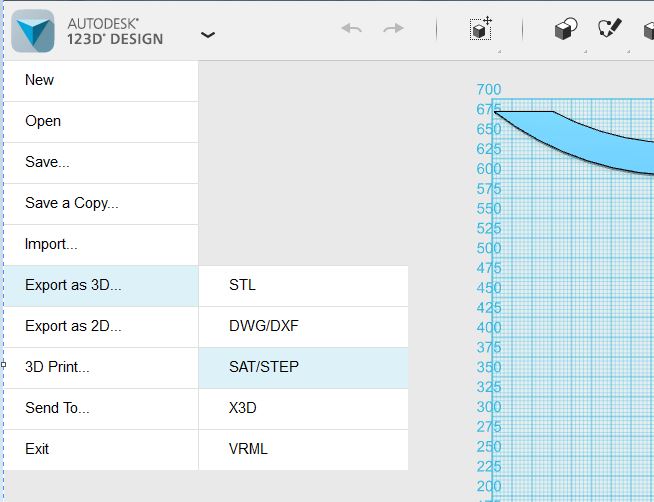
I exported the design in SAT/STEP format so that it can be opened
with Autodesk Inventor.
I installed Autodesk
Inventor HSM Express.
I opened the sat-file in Autodesk Inventor and selected CAM in the
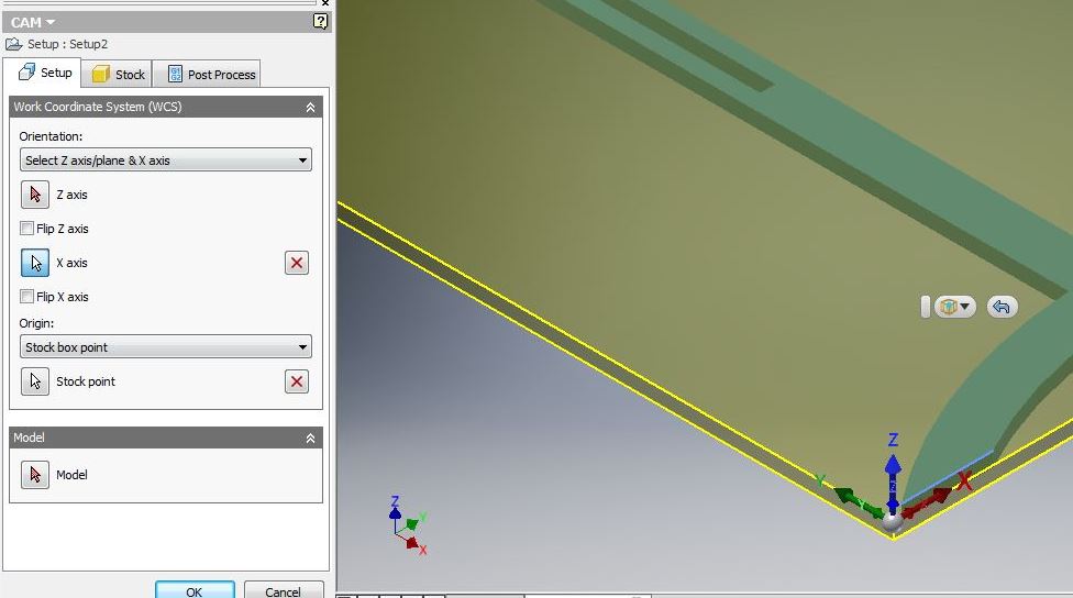
menu bar. The I selected Setup.
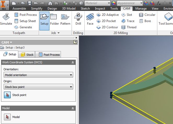
I set the stock and origin.
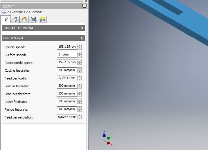
Tool and speed:
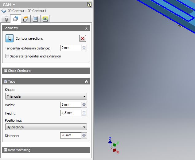
Tabs to hold the piece when the tool goes through:
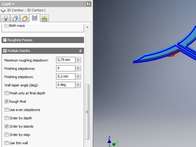
Maximum stepdown is small. We are using a home-made router, it has
to be driven very carefully.
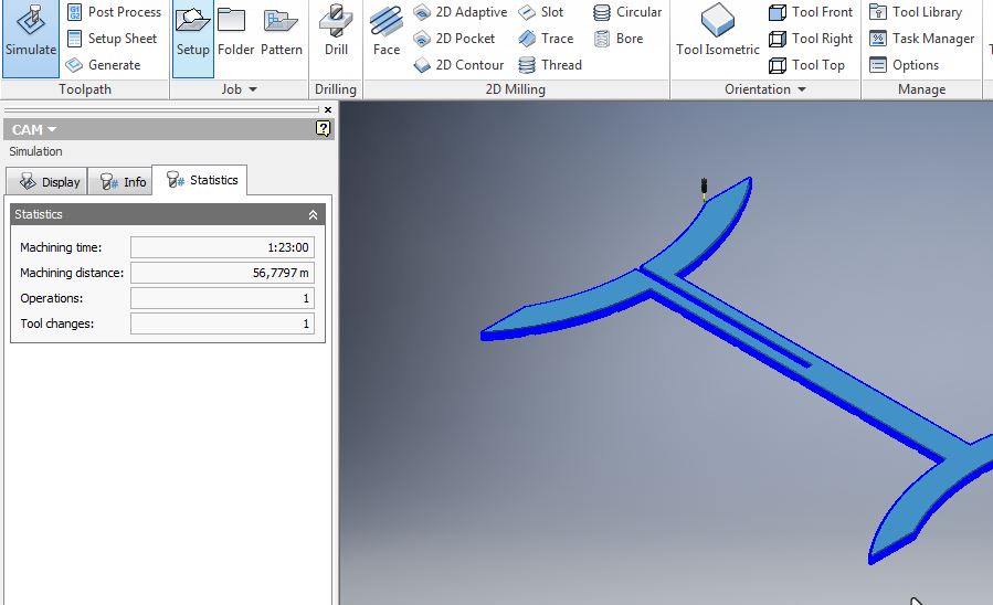
Simulator tool in HSM Express:
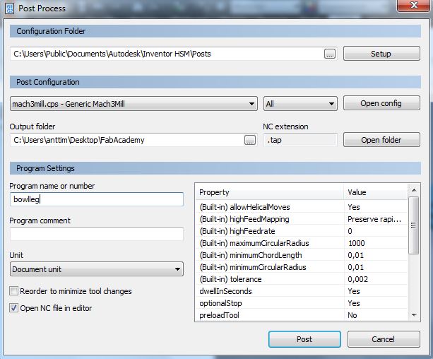
Post processing to G-code:
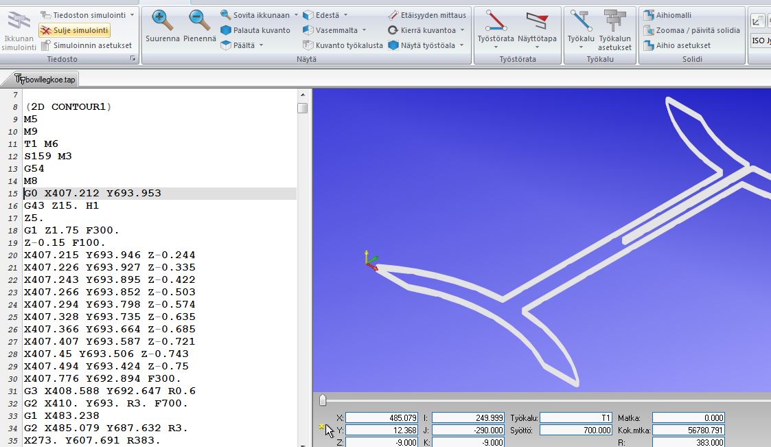
Inventor HSM Edit can also simulate the milling process:
Mach3 controls the stepper motor controlles:
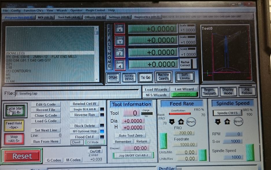
Our homemade router has manual spindle speed control, which was
turned to maximum, which is 12000 rpm.
Editing the G-code:
Before the G-code can be sent to our homemade router, lines starting
with G28 (Return to Reference Point Do) or G43 (Tool length offset)
must be deleted to prevent unpredictable behavior.
In action:
While routing the second part for the table leg, one of the belt
rollers for the Y-axis stepper motor fell off. I immediately stopped
the routing. Jani came to see why I stopped routing. In a panic we
forgot to take pictures, but it was scary. Nothing seemed to be
broken, so Jani attached the belt roller, and we started the routing
process from the beginning. To our big surprise, the origin had not
changed, and the routing path was the same as before the
catastrophe. Actually, the machine started working better.
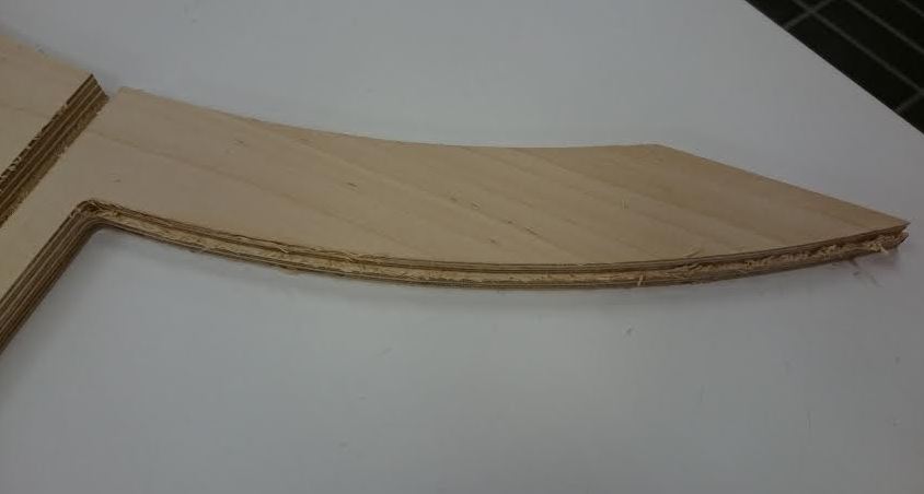
Every onece in a while there were sudden changes in the Y-axis
coordinates, which caused effects shown in the picture below. Those
were gone after fixing the belt roller. Maybe that was the reason...
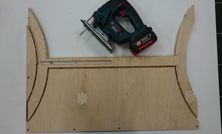
I loosened the part from the stock with a jigsaw.
And did a little bit sanding.
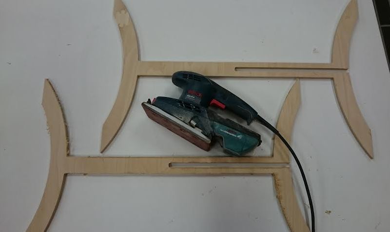
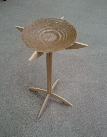
The final product looks like this:
Files:
123D Design file
123D Design sat-file
G-code
Bowlleg design process
Home