 INTERFACE AND APPLICATION PROGRAMMING
For this assignment week we had to write an application that interfaces with an input &/or output device that we made, comparing as many tool options as possible.
Input button interface
For this assignment week we had to write an application that interfaces with an input &/or output device that we made, comparing as many tool options as possible.
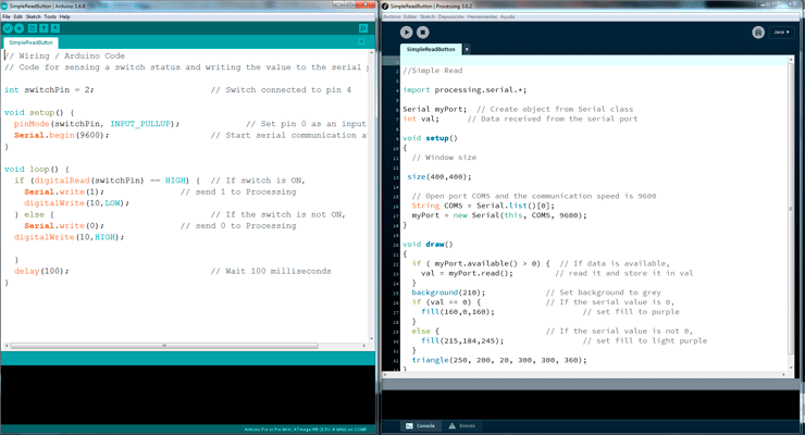
For me it was the first time that I tried to do an application interface and I started with processing with a simple read example, and I change the shape and the color of the element. I draw a purple triangle associate to the COM5, the same port that I used in Arduino, so when I press the button (pin2) in Arduino blue led (pin 10) is high and in processing the purple triangle became darker. I used the board of the sensor distance that I did in the input device class but with this example I just used the button and the led of the board to show the serial connection between Arduino and processing.
Processing arduino test1 from vretana on Vimeo.
// Processing code reading port test_Arduino

import processing.serial.*;

Serial myPort;  // Create object from Serial class
int val;      // Data received from the serial port

void setup()
{
 size(400,400);
  // Open port COM5.
  String COM5 = Serial.list()[0];
  myPort = new Serial(this, COM5, 9600);
}

void draw()
{
  if ( myPort.available() > 0) {  // If data is available,
    val = myPort.read();         // read it and store it in val
  }
  background(210);             // Set background to white
  if (val == 0) {              // If the serial value is 0,
    fill(160,0,160);                   // set fill to purple
  }
  else {                       // If the serial value is not 0,
    fill(215,184,245);                 // set fill to light purple
  }
  triangle(250, 200, 20, 300, 300, 360);
}
//Arduino code_test processing reading port

int switchPin = 2;                       // Switch connected to pin 4

void setup() {
  pinMode(switchPin, INPUT_PULLUP);             // Set pin 0 as an input
  Serial.begin(9600);                    // Start serial communication at 9600 bps
}

void loop() {
  if (digitalRead(switchPin) == HIGH) {  // If switch is ON,
    Serial.write(1);               // send 1 to Processing
    digitalWrite(10,LOW);
  } else {                               // If the switch is not ON,
    Serial.write(0);               // send 0 to Processing
  digitalWrite(10,HIGH);

  }
  delay(100);                            // Wait 100 milliseconds
}
Sensor distance interface
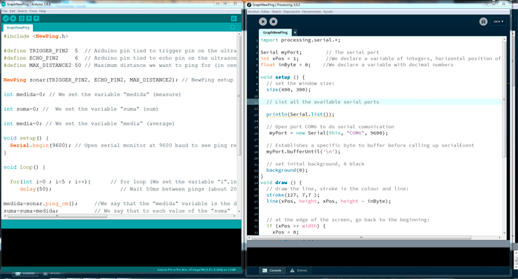
Then I tried to show visually the data that I receive from the sensor distance that I used in the input device class, so I started with the Arduino Graph example.
This was more difficult for me, at the beginning I just got two values from Arduino so it was just like a presence sensor but I couldn’t get gradual values, but I realized that one of the problems was that I wasn´t using a newline in Arduino so processing was taking every new value so as it just read the first time, also I had a problem because I was doing a serial print of ASCII values to see the distance in Arduino, but to do a serial connection with processing I can just print one value.
At the beginning I was taking the values directly from the sensor but it was too fast, so I decided to get an average of the sensor values and do a “serial.prinln” of them.
video processing distance graph from vretana on Vimeo.
// Processing code reading port test_Arduino graph

import processing.serial.*;

Serial myPort;        // The serial port
int xPos = 1;         //We declare a variable of integers, horizontal position of the graph
float inByte = 0;    //We declare a variable with decimal numbers

void setup () {
  // set the window size:
  size(400, 300);

  // List all the available serial ports

  println(Serial.list());

  // Open port COM6 to do serial comunication
   myPort = new Serial(this, "COM6", 9600);

  // Establishes a specific byte to buffer before calling up serialEvent
  myPort.bufferUntil('\n');

  // set inital background, 0 black
  background(0);
}
void draw () {
  // draw the line, stroke is the colour and line:
  stroke(127, 7,7 );
  line(xPos, height, xPos, height - inByte);


  // at the edge of the screen, go back to the beginning:
  if (xPos >= width) {
    xPos = 0;
    background(0);
  } else {
    // increment the horizontal position:
    xPos++;
  }
}

void serialEvent (Serial myPort) {
  // get the ASCII string:
  String inString = myPort.readStringUntil('\n');

  if (inString != null) {
    // trim off any whitespace:
    inString = trim(inString);
    // convert to an int and map to the screen height:
    inByte = float(inString);
    println(inByte);
    inByte = map(inByte, 0, 50, 0, height);
  }
}
//Arduino code_Arduino graph #include#define TRIGGER_PIN2 5 // Arduino pin tied to trigger pin on the ultrasonic sensor. #define ECHO_PIN2 6 // Arduino pin tied to echo pin on the ultrasonic sensor. #define MAX_DISTANCE2 50 // Maximum distance we want to ping for (in centimeters). Maximum sensor distance is rated at 400-500cm. NewPing sonar(TRIGGER_PIN2, ECHO_PIN2, MAX_DISTANCE2); // NewPing setup of pins and maximum distance. int medida=0; // We set the variable "medida" (measure) int suma=0; // We set the variable "suma" (sum) int media=0; // We set the variable "media" (average) void setup() { Serial.begin(9600); // Open serial monitor at 9600 baud to see ping results. } void loop() { for(int i=0 ; i<5 ; i++){ // for loop (We set the variable "i",initial value 0 end value 4, so we have 5 values, we add 1 to each value in the next round ) delay(50); // Wait 50ms between pings (about 20 pings/sec). 29ms should be the shortest delay between pings. medida=sonar.ping_cm(); //We say that the "medida" variable is the data we collect function with sonar.ping from the new ping library(cm) suma=suma+medida; // We say that to each value of the "suma" collected will let us add the loop collected as sensor value } media=suma/5; // "media" value is the sum value between 5 suma=0; // to start the loop again Serial.println(medida); // Print the values stored in the "medida" variable }