 OUTPUT DEVICES
Output assignment
For this week assignment we had to add an output device to a microcontroller board that we've designed and program it to do something.
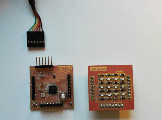
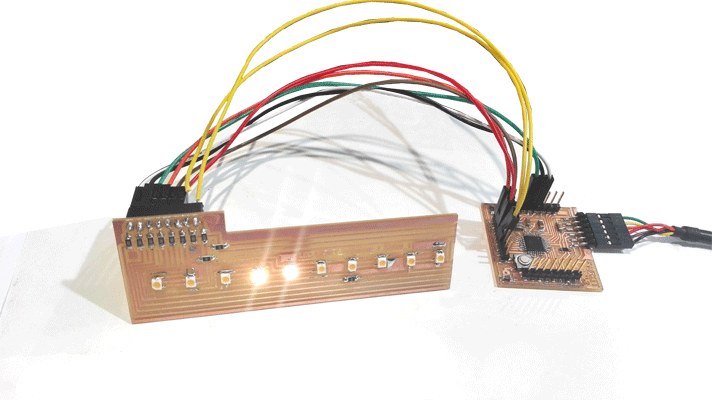
I chose the led array output because I want to use it in my final project, and I decided to do a board and connect it to the fabkit board that I did in the embedded programming class.
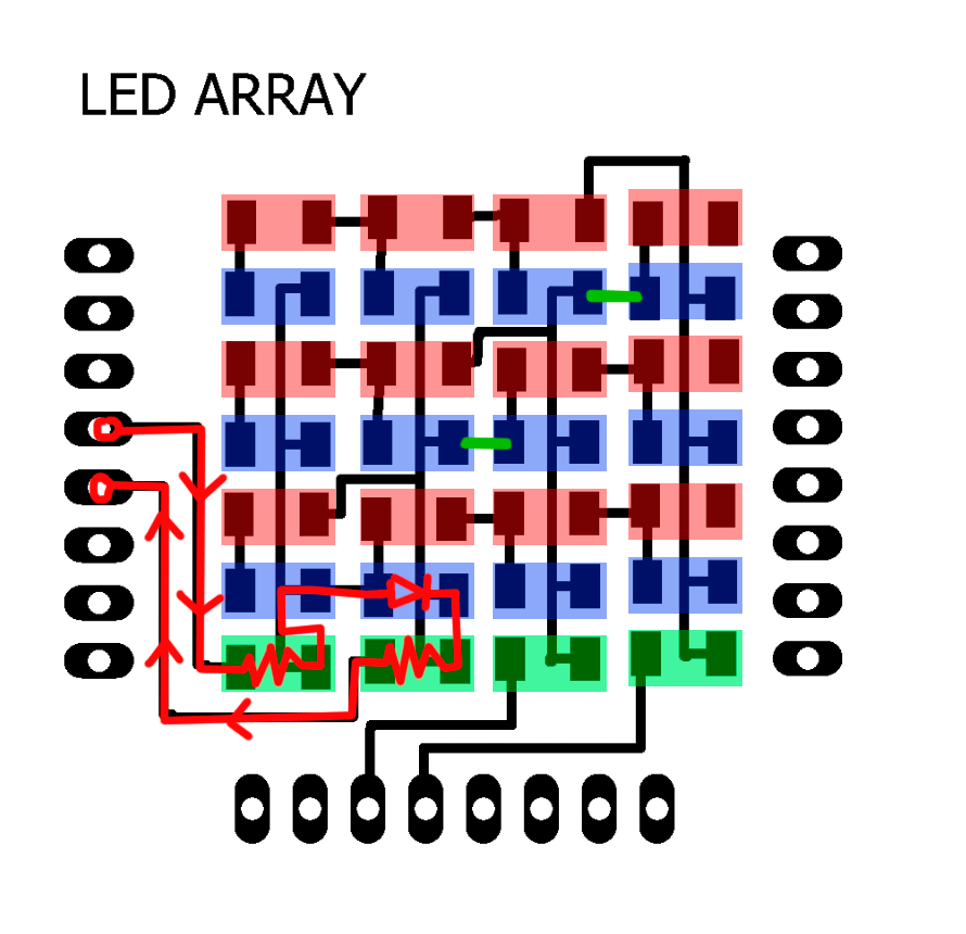
I read how Charlieplexing works , and I decided to do a matrix array (3x4).
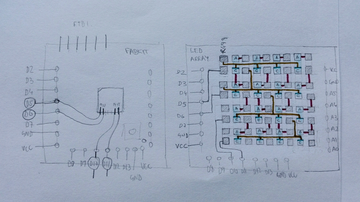
I draw it in eagle using the fabkit board because I needed that the holes were in the same place as in the fabkit.
I read the Atmel mega 168 A data sheet and then I decided which pins I should connect knowing what they do.
I used the PWM pins of the fabkit because I want to practice fade with the led array.
PD5:
- Arduino Fabkit pin:9
- OC0B_PWM
PD6:
- Arduino Fabkit pin:10
- OC0A_PWM
PB2:
- Arduino Fabkit pin:14
- OC1B_PWM
PB3:
- Arduino Fabkit pin:15
- OC2A_PWM
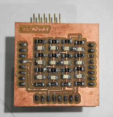
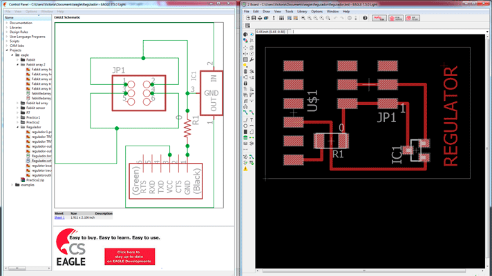
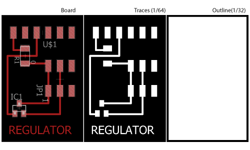
Schematic and Board eagle :
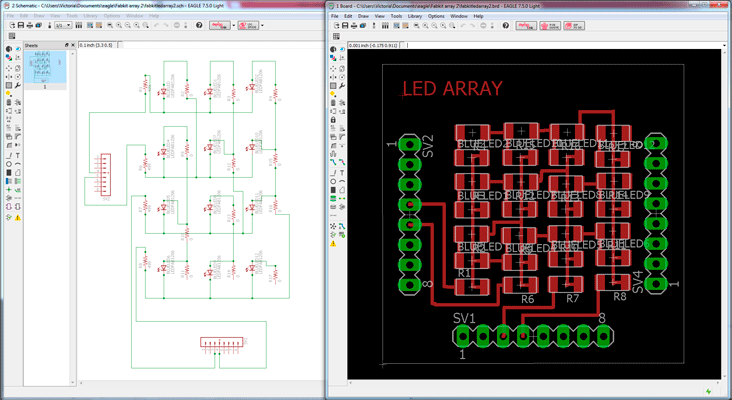
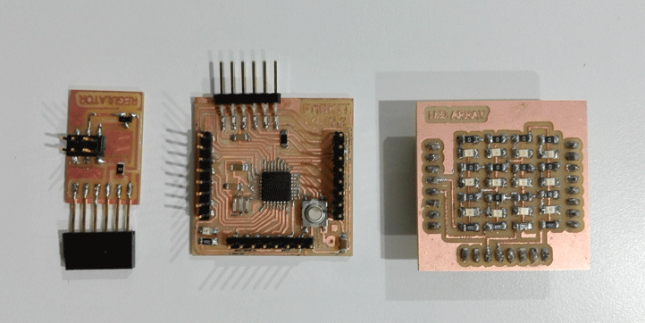
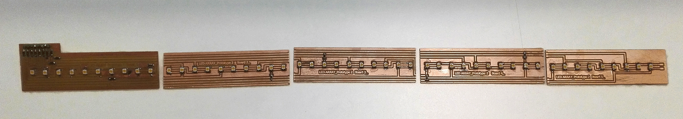
Led array boards:
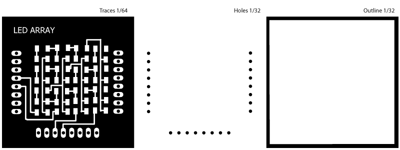
Boards
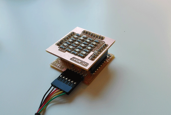
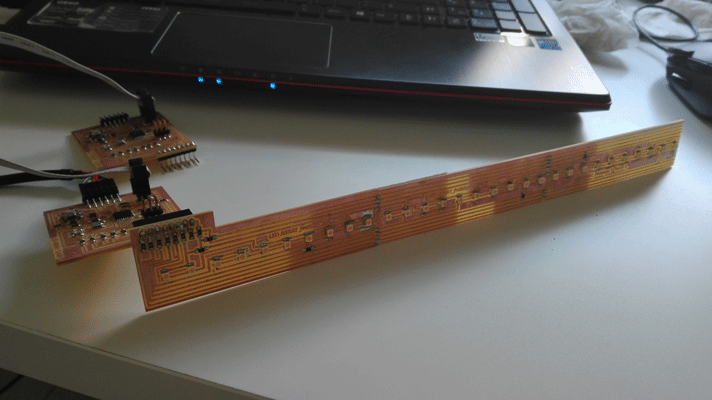
I started turning on the leds one by one and I realized that there was something wrong this the board because I couldn´t turn on all the leds, so I checked it an I saw the error and I could fix it just with a little bit of tin.
Charlieplex test:
charlieplex1 from vretana on Vimeo.
Charlieplex Code:
// include the charliplex library #include// define the number of pins #define NUMBER_OF_PINS 4 //define pins in the order you want to address them the adress of each will be 0,1,2,3 byte pins[] = {5, 6, 10, 11}; //initialize object Charlieplex charlieplex = Charlieplex(pins,NUMBER_OF_PINS); //write the adress of each led charliePin led1 = { 1, 0}; //led1 goes from 6 to 5 pin charliePin led2 = { 0 , 1 };//led2 goes from 5 to 6 pin charliePin led3 = { 0 , 2 };//led3 goes from 5 to 10 pin charliePin led4 = { 0 , 3 };//led1 goes from 5 to 11 pin charliePin led5 = { 2 , 0 }; charliePin led6 = { 2 , 1 }; charliePin led7 = { 1 , 2 }; charliePin led8 = { 1 , 3 }; charliePin led9 = { 3 , 0 }; charliePin led10 = { 3 , 1 }; charliePin led11 = { 3 , 2 }; charliePin led12 = { 2 , 3 }; boolean singleOn = false; void setup(){ /*nothing*/ } void loop(){ if (singleOn){ charlieplex.clear(); } // once I turn on each leds I clear the program // To turn the leds on I use the charlieWrite HIGH but to turn them off in charlieplex library it doesn´t work the LOW so I use charlieplex.clear to do it charlieplex.charlieWrite(led1,HIGH); delay(100); charlieplex.clear(); charlieplex.charlieWrite(led2,HIGH); delay(100); charlieplex.clear(); charlieplex.charlieWrite(led3,HIGH); delay(100); charlieplex.clear(); charlieplex.charlieWrite(led4,HIGH); delay(100); charlieplex.clear(); charlieplex.charlieWrite(led5,HIGH); delay(100); charlieplex.clear(); charlieplex.charlieWrite(led6,HIGH); delay(100); charlieplex.clear(); charlieplex.charlieWrite(led7,HIGH); delay(100); charlieplex.clear(); charlieplex.charlieWrite(led8,HIGH); delay(100); charlieplex.clear(); charlieplex.charlieWrite(led9,HIGH); delay(100); charlieplex.clear(); charlieplex.charlieWrite(led10,HIGH); delay(100); charlieplex.clear(); charlieplex.charlieWrite(led11,HIGH); delay(100); charlieplex.clear(); charlieplex.charlieWrite(led12,HIGH); delay(100); charlieplex.clear(); singleOn=!singleOn; }
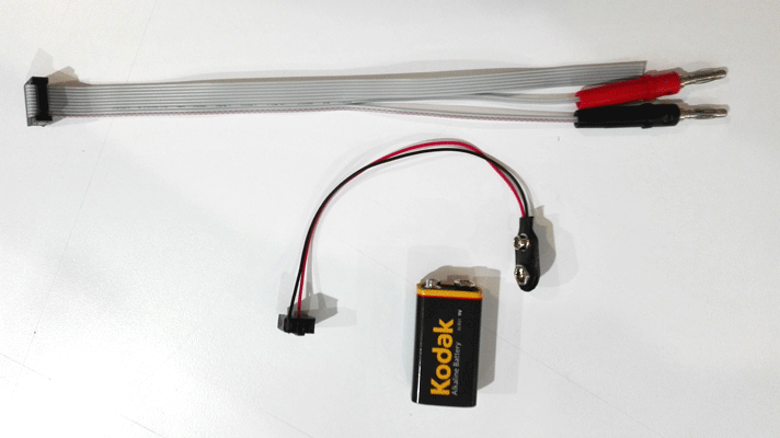
Regulator:
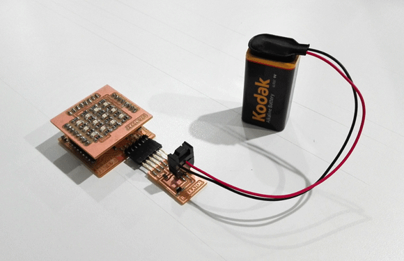
I did also a regulator board to connect and two cables, one for a battery and other for power supply, the component are:
- Regulator
- 6 Pin head
- 6 Pin head
- 0V Resistor
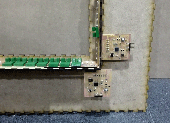
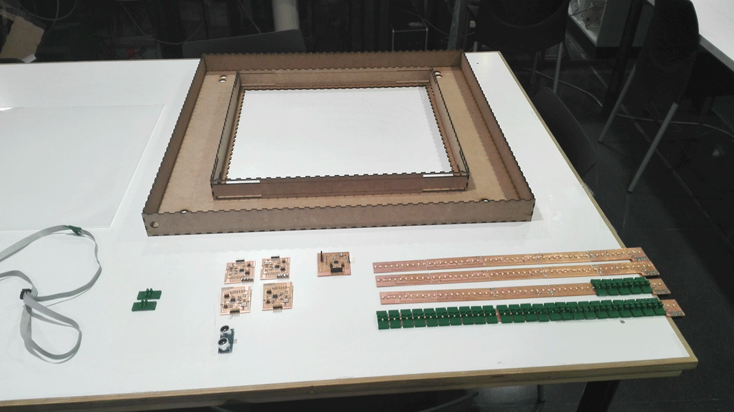
Final project Led array board + slave
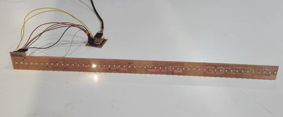
For my final project I design 4 LED array board and 4 slave board to be connected to the LED array board.
For the slave board I used the Atmel mega 168 A microcontroller.
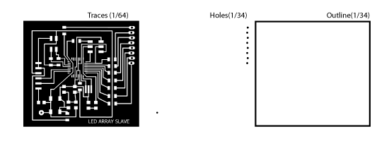
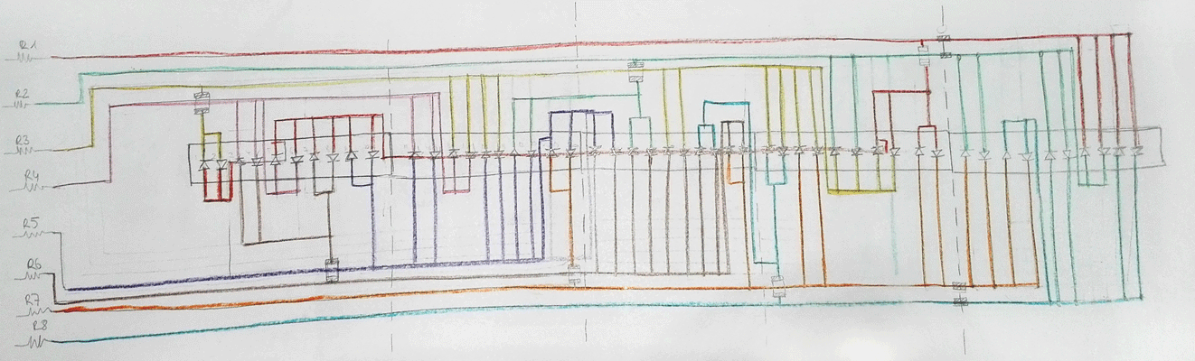
The first thing I did was to understand really haw the charlieplex work , so I design a 50 LEDs array board made by 5 boards connected with a little bit of tin, I had to divide the board in 5 because of the size of the Rolland mill and the size of the boards.
The complete led array board is 50cm long and 3 cm width.

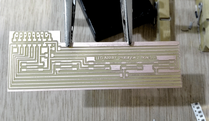
To test if the board was correctly design I used the fabkit board that I did in a week assignment to see if it worked, as it worked, I did the other three boards.
prototype 2_test 3 from vretana on Vimeo.
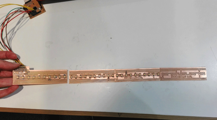
Once I knew that the LED array board worked with the fabkit I tested it with the slaves that I designed and also I tested the I2C communication and it also worked.
Programming the slave board
// Slave programming // include the wire library #include// include the charlieplex library #include // We establish the number of pins that will work #define NUMBER_OF_PINS 8 //We establish the pins that go to work and in the order they will work byte pins[] = {16, 11, 10, 9,8,7,6,5}; //we set the variable x as a volatile variable volatile int x; //We started the charlieplex Charlieplex victoria = Charlieplex(pins,NUMBER_OF_PINS); //write le address of each led charliePin led1 = { 0 , 2}; //led1 goes from 16 to 10 pin charliePin led2 = { 2 , 0}; //led1 goes from 10 to 16 pin charliePin led3 = { 5 , 3}; charliePin led4 = { 3 , 5}; charliePin led5 = { 3 , 0}; charliePin led6 = { 0 , 3}; charliePin led7 = { 5 , 0}; charliePin led8 = { 0 , 5}; charliePin led9 = { 4 , 0}; charliePin led10 = { 0 , 4}; charliePin led11 = { 4 , 3}; charliePin led12 = { 3 , 4}; charliePin led13 = { 3 , 2}; charliePin led14 = { 2 , 3}; charliePin led15 = { 4 , 2}; charliePin led16 = { 2 , 4}; charliePin led17 = { 4 , 1}; charliePin led18 = { 1 , 4}; charliePin led19 = { 6 , 4}; charliePin led20 = { 4 , 6}; charliePin led21 = { 5 , 4}; charliePin led22 = { 4 , 5}; charliePin led23 = { 5 , 1}; charliePin led24 = { 1 , 5}; charliePin led25 = { 5 , 2}; charliePin led26 = { 2 , 5}; charliePin led27 = { 5 , 7}; charliePin led28 = { 7 , 5}; charliePin led29 = { 6 , 5}; charliePin led30 = { 5 , 6}; charliePin led31 = { 7 , 2}; charliePin led32 = { 2 , 7}; charliePin led33 = { 6 , 2}; charliePin led34 = { 2 , 6}; charliePin led35 = { 2 , 1}; charliePin led36 = { 1 , 2}; charliePin led37 = { 2 , 0}; charliePin led38 = { 0 , 2}; charliePin led39 = { 6 , 0}; charliePin led40 = { 0 , 6}; charliePin led41 = { 6 , 1}; charliePin led42 = { 1 , 6}; charliePin led43 = { 6 , 7}; charliePin led44 = { 7 , 6}; charliePin led45 = { 7 , 1}; charliePin led46 = { 1 , 7}; charliePin led47 = { 1 , 0}; charliePin led48 = { 0 , 1}; charliePin led49 = { 7 , 0}; charliePin led50 = { 0 , 7}; boolean singleOn = false; void setup() { Wire.begin(2); // we start i2c communication and we call this slave 2 Wire.onReceive(receiveEvent); // the slave is receiving information Serial.begin(9600); // we set the communication by the serial port and the communication speed pinMode (13,OUTPUT); // we set the pin 13 as output } void loop() {if (x==1){ // if x = 1, the LEDs are lit, and clean all the information each time we change led if (singleOn){ victoria.clear(); } victoria.charlieWrite(led1,HIGH); delay(100); victoria.clear(); victoria.charlieWrite(led2,HIGH); delay(100); victoria.clear(); victoria.charlieWrite(led3,HIGH); delay(100); victoria.clear(); victoria.charlieWrite(led4,HIGH); delay(100); victoria.clear(); victoria.charlieWrite(led5,HIGH); delay(100); victoria.clear(); victoria.charlieWrite(led6,HIGH); delay(100); victoria.clear(); victoria.charlieWrite(led7,HIGH); delay(100); victoria.clear(); victoria.charlieWrite(led8,HIGH); delay(100); victoria.clear(); victoria.charlieWrite(led9,HIGH); delay(100); victoria.clear(); victoria.charlieWrite(led10,HIGH); delay(100); victoria.clear(); victoria.charlieWrite(led11,HIGH); delay(100); victoria.clear(); victoria.charlieWrite(led12,HIGH); delay(100); victoria.clear(); victoria.charlieWrite(led13,HIGH); delay(100); victoria.clear(); victoria.charlieWrite(led14,HIGH); delay(100); victoria.clear(); victoria.charlieWrite(led15,HIGH); delay(100); victoria.clear(); victoria.charlieWrite(led16,HIGH); delay(100); victoria.clear(); victoria.charlieWrite(led17,HIGH); delay(100); victoria.clear(); victoria.charlieWrite(led18,HIGH); delay(100); victoria.clear(); victoria.charlieWrite(led19,HIGH); delay(100); victoria.clear(); victoria.charlieWrite(led20,HIGH); delay(100); victoria.clear(); victoria.charlieWrite(led21,HIGH); delay(100); victoria.clear(); victoria.charlieWrite(led22,HIGH); delay(100); victoria.clear(); victoria.charlieWrite(led23,HIGH); delay(100); victoria.clear(); victoria.charlieWrite(led24,HIGH); delay(100); victoria.clear(); victoria.charlieWrite(led25,HIGH); delay(100); victoria.clear(); victoria.charlieWrite(led26,HIGH); delay(100); victoria.clear(); victoria.charlieWrite(led27,HIGH); delay(100); victoria.clear(); victoria.charlieWrite(led28,HIGH); delay(100); victoria.clear(); victoria.charlieWrite(led29,HIGH); delay(100); victoria.clear(); victoria.charlieWrite(led30,HIGH); delay(100); victoria.clear(); victoria.charlieWrite(led31,HIGH); delay(100); victoria.clear(); victoria.charlieWrite(led32,HIGH); delay(100); victoria.clear(); victoria.charlieWrite(led33,HIGH); delay(100); victoria.clear(); victoria.charlieWrite(led34,HIGH); delay(100); victoria.clear(); victoria.charlieWrite(led35,HIGH); delay(100); victoria.clear(); victoria.charlieWrite(led36,HIGH); delay(100); victoria.clear(); victoria.charlieWrite(led37,HIGH); delay(100); victoria.clear(); victoria.charlieWrite(led38,HIGH); delay(100); victoria.clear(); victoria.charlieWrite(led39,HIGH); delay(100); victoria.clear(); victoria.charlieWrite(led40,HIGH); delay(100); victoria.clear(); victoria.charlieWrite(led41,HIGH); delay(100); victoria.clear(); victoria.charlieWrite(led42,HIGH); delay(100); victoria.clear(); victoria.charlieWrite(led43,HIGH); delay(100); victoria.clear(); victoria.charlieWrite(led44,HIGH); delay(100); victoria.clear(); victoria.charlieWrite(led45,HIGH); delay(100); victoria.clear(); victoria.charlieWrite(led46,HIGH); delay(100); victoria.clear(); victoria.charlieWrite(led47,HIGH); delay(100); victoria.clear(); victoria.charlieWrite(led48,HIGH); delay(100); victoria.clear(); victoria.charlieWrite(led49,HIGH); delay(100); victoria.clear(); victoria.charlieWrite(led50,HIGH); delay(100); victoria.clear(); singleOn=!singleOn;} else{//if x is other than 1 LEDs are off victoria.clear(); } delay(100); } // function that runs whenever you receive something from the master void receiveEvent(int holaa) { // i2c communication we received x= Wire.read ();// we read by i2c the x value }