 INPUT DEVICES

Input assignment
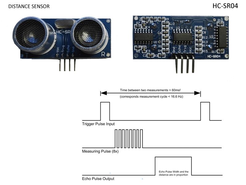
For this assignment week we have to measure something: add a sensor to a microcontroller board that you have designed and read it, so I decided to do it with the sensor that I am going to use in my final project, the distance sensor.
Designing the board
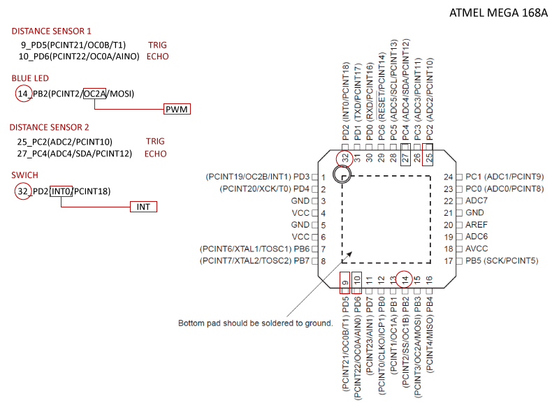
The first thing I did to design the board it was to read the data sheet of the Atmel mega 168 A and see which pins are connected to the Fabkit microcontroller pins and what all they do, knowing that I used the following pins:
Distance Sensor 1:
- VCC_ VCC_ VCC
- Echo_ D6_Pin 6
- Trig_D5_Pin 5
- GND_ GND_ GND
Distance Sensor 2:
- GND_ GND_ GND
- Trig_A2_ Pin 16
- Echo_ A4_Pin 18
- VCC_ VCC_ VCC
Resistor and led:
- D10_ Pin 14
- GND_GND
Swich:
- D2_Pin32
- GND_GND
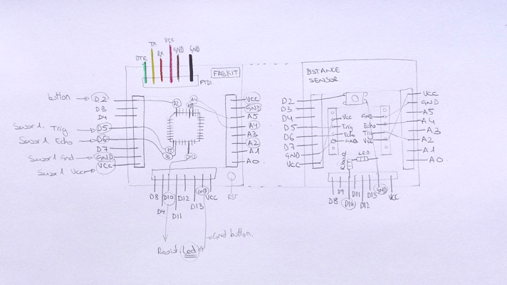
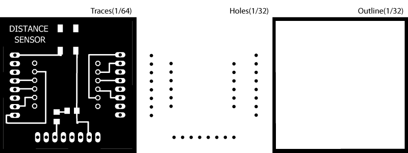
In the embedded programming assignment I did the Fabkit board and now I decided to used it, so I design the new board using the Fabkit eagle files because I needed that the heads were in the same place in order to connect them. The distance sensor board components are:
- 3x 8 pin head
- 2x 6 pin head (I will connect just 4 pins of each head, trig, echo, GND and VCC)
- Clear blue led, I decided to connect a LED with a PWM pin to practice fade.
- 100 Ω Resistor
- Swich, I decided to connect a SWICH with an INT pin to practice interruptions.
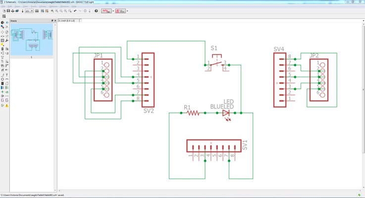
Schematic eagle file:
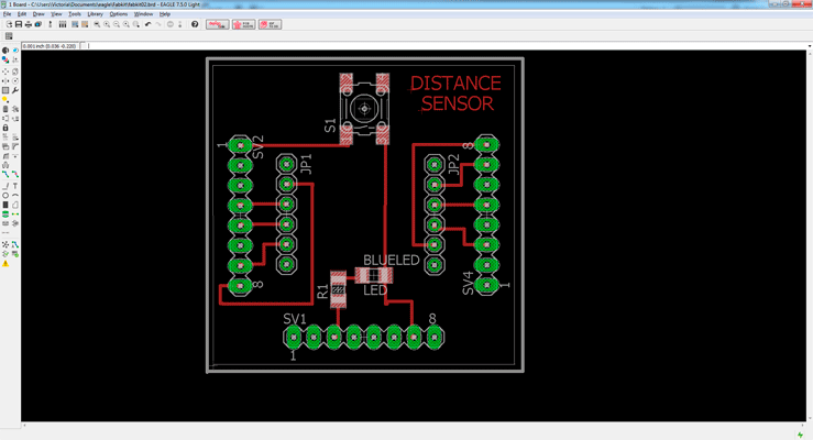
Board eagle file:
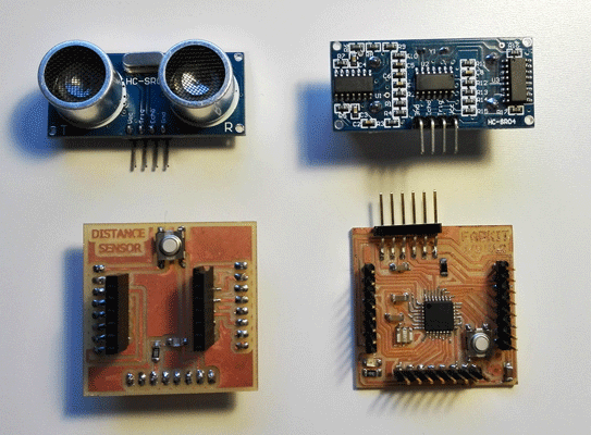
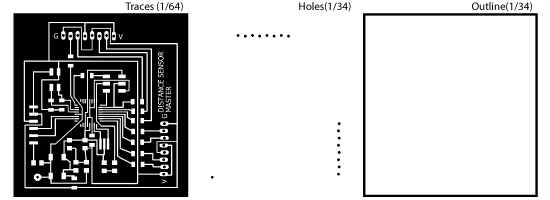
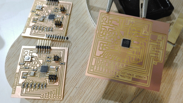
Boards files:
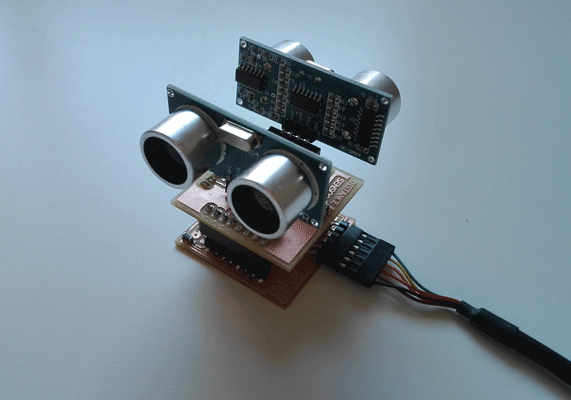
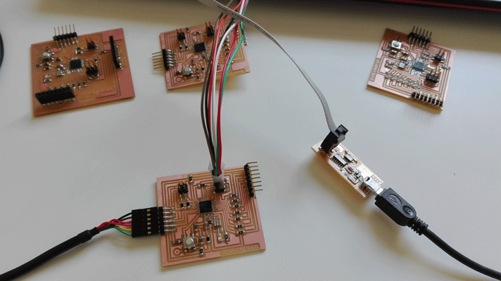
Boards and sensors that I used:
Arduino programming
Once I milled the board, soldered the components and test the connections I tried to program it in Arduino, the first thing I did was to download the Arduino NewPing library and I did the examples using my TRIGGER_PIN and ECHO_PIN. I have two Distance Sensor I test both of them and both worked.
Measuring distances
The first example is the NewPing example and I tested if the board if the sensor measures the distance and it worked.
DistanceSensor1 from vretana on Vimeo.
#include// define the number of the pins I am using the fabkit board with ATMega168A so: #define TRIGGER_PIN 5 // pin that send a signal #define ECHO_PIN 6 // pin that receive the signal #define MAX_DISTANCE 400 // max distance that the sensor will read NewPing sonar(TRIGGER_PIN, ECHO_PIN, MAX_DISTANCE); // establish the new ping telling which are the pins and the max distance //the setup routine runs once when you press reset void setup() { Serial.begin(9600); // establish the communication between the computer and the board and the communication speed } // the loop routine runs in loop forever: void loop() { delay(50); // wait 50 miliseconds int uS = sonar.ping(); // converts a value into a data type (uS microseconds) Serial.print("Ping: "); // print data from a serial port as readable text in ASCII Serial.print(uS / US_ROUNDTRIP_CM); // print data from a serial port as readable text in ASCII (convert microseconds in centimeters) Serial.println("cm");// print data from a serial port as readable text in ASCII (cm centimeters) }
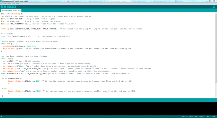
Measuring distances + led
Then I tried to program the Fabkit led, if the distance between the sensor and the object is bigger than 10 cm the led is LOW but if it is smaller the led is HIGH.
DistanceSensor2 from vretana on Vimeo.
#include// define the number of the pins I am using the fabkit board with ATMega168A so: #define TRIGGER_PIN 5 // pin that send a signal #define ECHO_PIN 6 // pin that receive the signal #define MAX_DISTANCE 400 // max distance that the sensor will read NewPing sonar(TRIGGER_PIN, ECHO_PIN, MAX_DISTANCE); // establish the new ping telling which are the pins and the max distance // contants: const int ledPinGreen = 13; // the number of the LED pin //the setup routine runs once when you press reset void setup() { pinMode(ledPinGreen, OUTPUT); Serial.begin(9600); // establish the communication between the computer and the board and the communication speed } // the loop routine runs in loop forever: void loop() { delay(50); // wait 50 miliseconds int uS = sonar.ping(); // converts a value into a data type (uS microseconds) Serial.print("Ping: "); // print data from a serial port as readable text in ASCII Serial.print(uS / US_ROUNDTRIP_CM); // print data from a serial port as readable text in ASCII (convert microseconds in centimeters) Serial.println("cm");// print data from a serial port as readable text in ASCII (cm centimeters) long distanceCm = uS / US_ROUNDTRIP_CM;// print data from a serial port as readable text in ASCII (cm centimeters) if(distanceCm>10){ digitalWrite(ledPinGreen,LOW);// if the distance of the distance sensor is bigger than 10cm the led pin is LOW } else{ digitalWrite(ledPinGreen,HIGH);// if the distance of the distance sensor is smaller than 10cm the led pin is HIGH } }
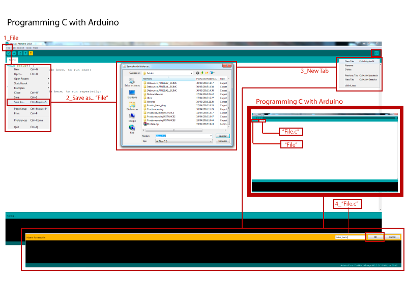
Programming C using Arduino
This week we also learn how to do C programming using arduino:
To do it we have to open a new project and save it with a "name file", open a new tab and save it with the same name file but .c ("name file.c") and save the two files in the same arduino file. In the "name file.c" we can use C programmig and sent it to the board.
I tried to do a blink example in C, for me it was the first time that I did C programming but it worked, next stage it would be try to do the sensor reading with C.
/* include the libraries that we are going to use*/ /* pins library*/ #include/* delay library time libraries*/ #include /* include all the funtions that we are going to use blink and then a 1000ms delay*/ #define BLINK_DELAY_MS 1000 /* a function is called when a sketch starts*/ int main (void) { /* set pin PB5 of PORTB for output*/ DDRB |= _BV(DDB5); /* main loop*/ while(1) { /* set PB5 PIN 17 high to turn led on */ PORTB |= _BV(PORTB5); _delay_ms(BLINK_DELAY_MS); /* set pin PB5 PIN 17 low to turn led off */ PORTB &= ~_BV(PORTB5); _delay_ms(BLINK_DELAY_MS); } }}
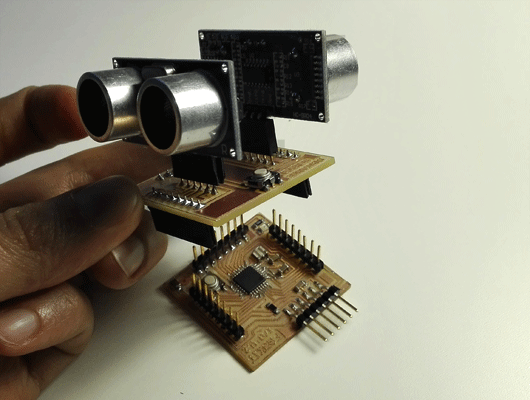
Final project master board
For my final project I also used the distance sensor input, and I design a master board to connect it.
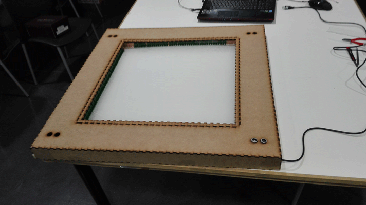
The LED starts to light up when someone is closer than 20 cm. And the light is transmitted through the lines etched in the acrylic.
I did the master board using the Atmel mega 168A microcontroller.
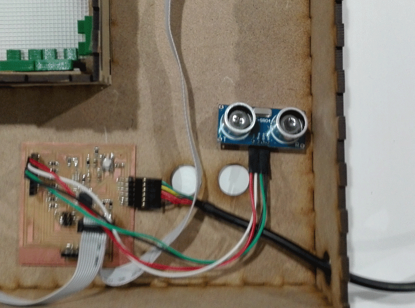
The input that I used was the distance sensor HC-SR04. The master board has space to connect up to four distance sensors but for the project I just connect one. And I connect it using wires, I did several holes in the MDF structure in order to put the sensor anywhere you want.
Programming the master board
I used I2C communication to send the order to the slaves.
// Master programming // include the wire library #include// include the NewPing library #include // define the number of the pins I am using the fabkit board with ATMega168A so: #define TRIGGER_PIN 5 // pin that send a signal #define ECHO_PIN 6 // pin that receive the signal #define MAX_DISTANCE 400 // max distance that the sensor will read NewPing sonar(TRIGGER_PIN, ECHO_PIN, MAX_DISTANCE); // establish the new ping telling which are the pins and the max distance // contants: const int ledPinGreen = 13; // the number of the LED pin //the setup routine runs once when you press reset void setup() { Wire.begin(); // join i2c bus (address optional for master) pinMode(ledPinGreen, OUTPUT); Serial.begin(9600); // establish the communication between the computer and the board and the communication speed } byte x = 0; // the loop routine runs in loop forever: void loop() { delay(50); // wait 50 miliseconds int uS = sonar.ping(); // converts a value into a data type (uS microseconds) Serial.print("Ping: "); // print data from a serial port as readable text in ASCII Serial.print(uS / US_ROUNDTRIP_CM); // print data from a serial port as readable text in ASCII (convert microseconds in centimeters) Serial.println("cm");// print data from a serial port as readable text in ASCII (cm centimeters) long distanceCm = uS / US_ROUNDTRIP_CM;// print data from a serial port as readable text in ASCII (cm centimeters) Wire.beginTransmission(2); // transmit to device #2 if(distanceCm>20){ x=0; } else{ x=1; } Wire.write(x); Wire.endTransmission(2); // stop transmitting delay(500); }