 EMBEDDED PROGRAMMING

For this assignment week we had to do embedded programming.
So I decided to program the hello-world board that I did in the electronics production assignment using hello.ISP.44 programmer and also I did the fabkit arduino.
The first thing that I did was to download:
- The FabISP drivers https://learn.adafruit.com/usbtinyisp/drivers
- FTDI cable drivers http://www.ftdichip.com/Drivers/VCP.htm
- Arduino exe https://www.arduino.cc/download_handler.php?f=/arduino-1.6.8-windows.zip
- Attiny support http://highlowtech.org/?p=1695
- WinAVR (C) https://sourceforge.net/projects/winavr/
Reading the Attiny 44 Data Sheet
Word size: the memory is divided in blocks, the blocks can be 8,16,32 0r 64 bits. Attiny 44 microcontroller is divided in 8 bits.
1 byte: 8 bits
In each bite there are just two possible values
- 0-1
- LOW-HIGH
- 0-5V
Peripherals are the different functions inside the microcontroller
- A/D Analog Digital converter
- Comparator
- D/A Digital Analog converter
The hello-word microcontroller is Attiny 44 so I read the data sheet, there I found all the pin of it and what they all do.
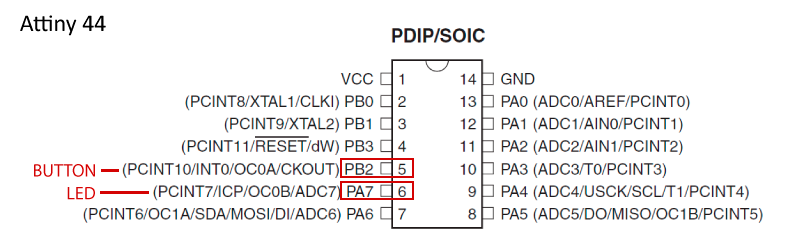
VCC
That supply voltage.
GND
Ground.
Port B (PB3:PB0)
Port B is a 4-bit bi-directional I/O port with internal pull-up resistors (selected for each bit).
As inputs, Port B pins that are externally pulled low will source current if the pull-up resistors are activated.
RESET
Reset input, to start again the program.
Port A (PA7:PA0)
Port A is a 8-bit bi-directional I/O port with internal pull-up resistors (selected for each bit).
As inputs, Port A pins that are externally pulled low will source current if the pull-up resistors are activated.
Port A has alternate functions as analog inputs for the ADC, analog comparator, timer/counter, SPI and pin change interrupt.
Programming the Hello-World board
Then I tried to program the hello-world board but I found errors doing it, so I checked both boards and I realized that when I milled the hello-world board a few wires were too closed to each other so there weren’t cut, and also I had a problem with the hello.ISP.44 a capacitor was burned so changed it..
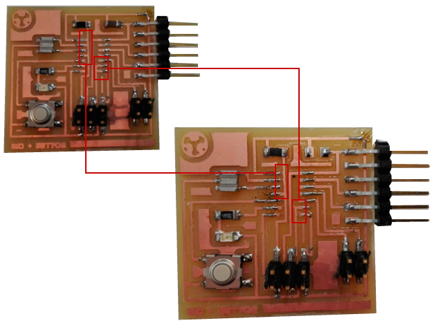
Finally I could program it.
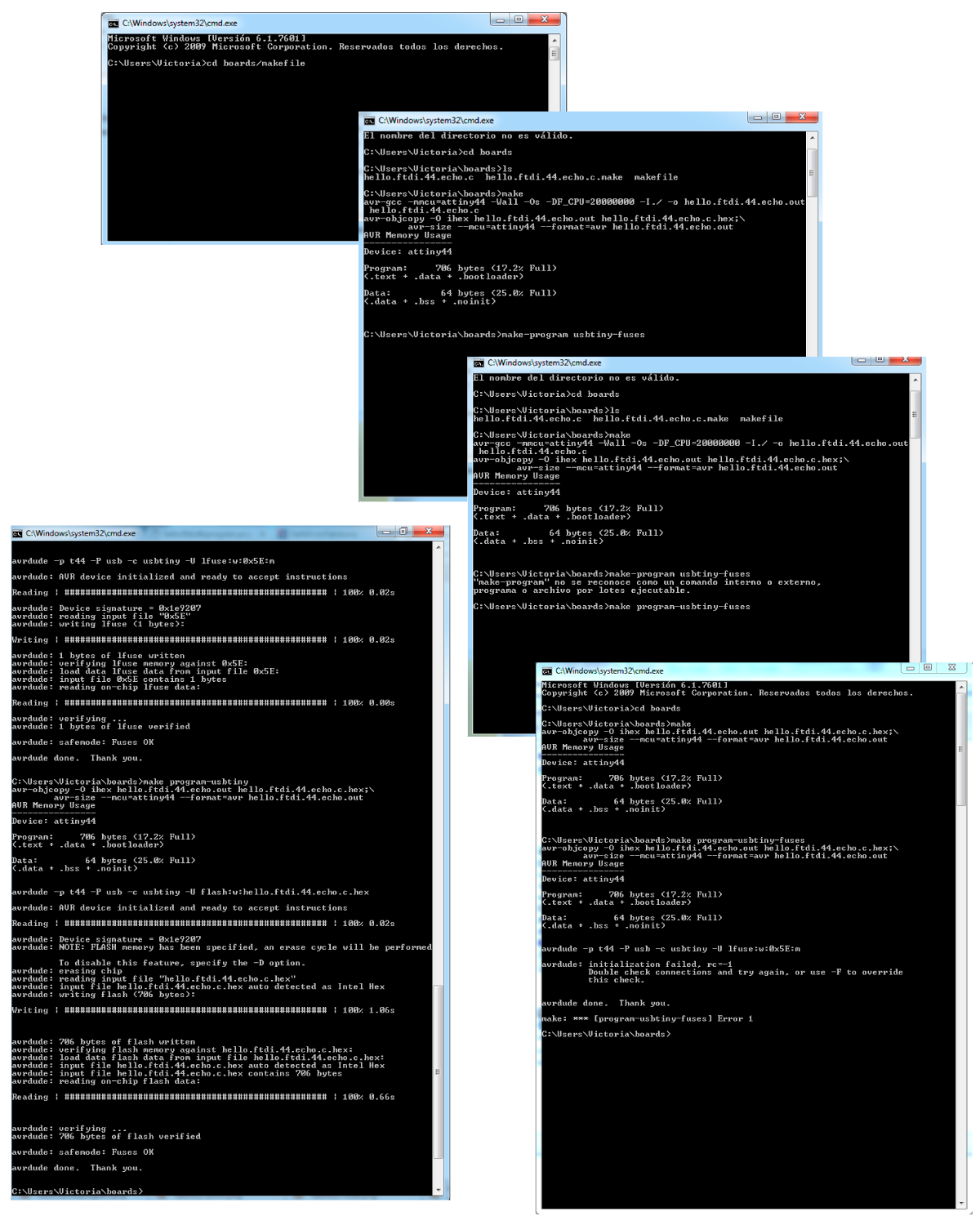
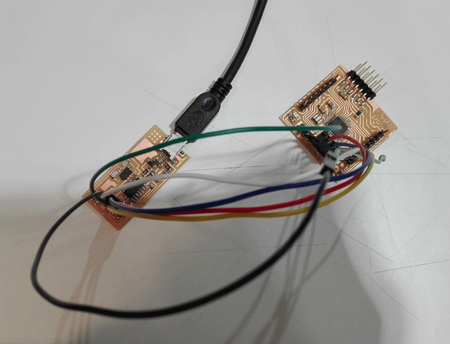
After trying to program the hello-world board several times unsatisfactorily I tried the same from one of my fablab’s computers and it worked, so I think there is something wrong with my USB ports, and this it just happen to me when I use the programmer board, but when I try to program other boards I don’t have any problem.
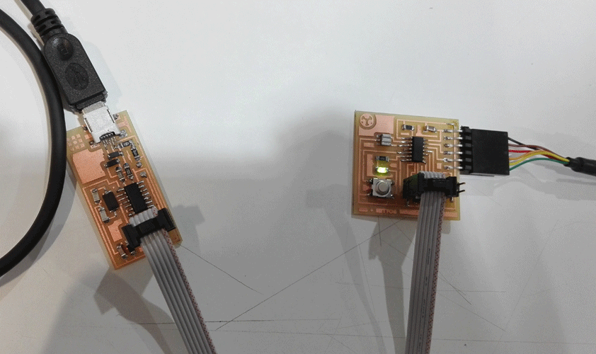
To program the hello-world board in Arduino I chose the Attiny 44 with 20 MHz Clock ,the USB tiny programmer and the Serial port.
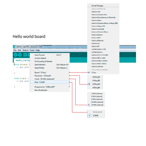
I decided to make a program that blink the led 50 miliseconds HIGH and 50 miliseconds LOW and if I push the button it make the same but 500 miliseconds.
	  // button with two kinds of blink

	// constants won't change.
	// set pin numbers:
	const int buttonPin = 8;     // the number of the pushbutton pin
	const int ledPin =  7;      // the number of the LED pin

	// variables will change:
	int buttonState = 0;         // variable for reading the pushbutton status

	void setup() {
	// initialize the LED pin as an output:
	pinMode(ledPin, OUTPUT);
	// initialize the pushbutton pin as an input with the internal pull-up resistor enabled
	pinMode(buttonPin, INPUT_PULLUP);
	}

	void loop() {
	// read the state of the pushbutton value:
	buttonState = digitalRead(buttonPin);

	// check if the pushbutton is pressed.
	// if it is, the buttonState is HIGH:
	if (buttonState == HIGH) {
		// turn LED on 50 miliseconds:
		digitalWrite(ledPin, HIGH);
		delay (50);
		// turn LED off 50 miliseconds:
		digitalWrite(ledPin, LOW);
		delay (50);

	// if the buttonState is LOW:
	} else {
		// turn LED on 500 miliseconds:
		digitalWrite(ledPin, HIGH);
		delay (500);
		// turn LED on 500 miliseconds:
		digitalWrite(ledPin, LOW);
		delay (500);
	}
	}
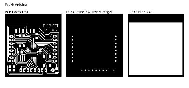
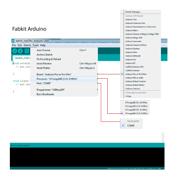
Programming the Fabkit board
Then I tried to program the hello-world board but I found errors doing it, so I checked both boards and I realized that when I milled the hello-world board a few wires were too closed to each other so there weren’t cut, and also I had a problem with the hello.ISP.44 a capacitor was burned so changed it..
Fabkit-blink (1) from vretana on Vimeo.
	//Fabkit blink


// the setup function runs once when you press reset or power the board
void setup() {
  // initialize digital pin 13 as an output.
  pinMode(13, OUTPUT);
}

// the loop function runs over and over again forever
void loop() {
    digitalWrite(13, HIGH);   // turn the LED on (HIGH is the voltage level)
  delay(50);              // wait for 50 miliseconds
  digitalWrite(13, LOW);    // turn the LED off by making the voltage LOW
  delay(50);              // wait for 50 miliseconds

  digitalWrite(13, HIGH);   // turn the LED on (HIGH is the voltage level)
  delay(100);              // wait for 100 miliseconds
  digitalWrite(13, LOW);    // turn the LED off by making the voltage LOW
  delay(100);              // wait for 100 miliseconds

  digitalWrite(13, HIGH);   // turn the LED on (HIGH is the voltage level)
  delay(200);              // wait for 200 miliseconds
  digitalWrite(13, LOW);    // turn the LED off by making the voltage LOW
  delay(200);               // wait for 200 miliseconds

    digitalWrite(13, HIGH);   // turn the LED on (HIGH is the voltage level)
  delay(300);              // wait for 300 miliseconds
  digitalWrite(13, LOW);    // turn the LED off by making the voltage LOW
  delay(300);              // wait for 300 miliseconds

  digitalWrite(13, HIGH);   // turn the LED on (HIGH is the voltage level)
  delay(400);              // wait for 400 miliseconds
  digitalWrite(13, LOW);    // turn the LED off by making the voltage LOW
  delay(400);               // wait for 400 miliseconds

  digitalWrite(13, HIGH);   // turn the LED on (HIGH is the voltage level)
  delay(500);              // wait for 500 miliseconds
  digitalWrite(13, LOW);    // turn the LED off by making the voltage LOW
  delay(500);               // wait for 500 miliseconds
}