The assignment for this week was to read a microcontroller data sheet and program my echo hello world board to do something, with as many different programming languages and programming environments as possible. The data sheet was the Amtel 8-bit Microcontroller with 2K/4K/8K Bytes In-System Programmable Flash data sheet. This is the same data sheet as the ATtiny 44A used on my board.
I decided to read the data sheet once through and then go back and look at each indvidual section. After my first read through, I figured out the data sheet for the microcontroller was the complete encyclopedia on the ATtiny 44A I used on my board. It covers everything you would need to know about the part. It provides essential information about everything. Because a microcontroller can perform so many operations, the data sheet ballooned in size because each operation is covered in immense detail. The data sheet I read also grouped the ATtiny 44A with others in the same family. The ATtiny 24A and 84A were also described. This family grouping allows the manufacturer to describe the microcontroller family without having write a manual for each microcontroller.
The data sheet started with a quick overview of the microcontroller family and then went into 27 sections. The sections were in descending order:
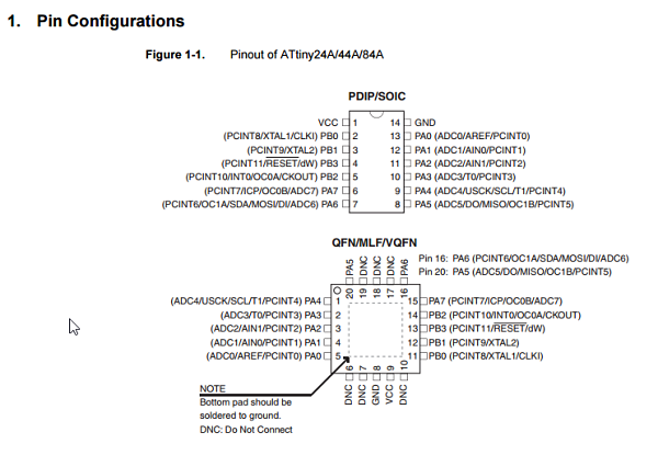
The data sheet as said before contains an enormous amount of detailed information. Once I looked at the data sheet a second time and absorbed the general overview, it started to make more sense and provide the information needed to use the data sheet. The most basic information and useful for my very basic usage was the Pin Configuration. The showed exactly how the pins were laid out on the microcontroller.
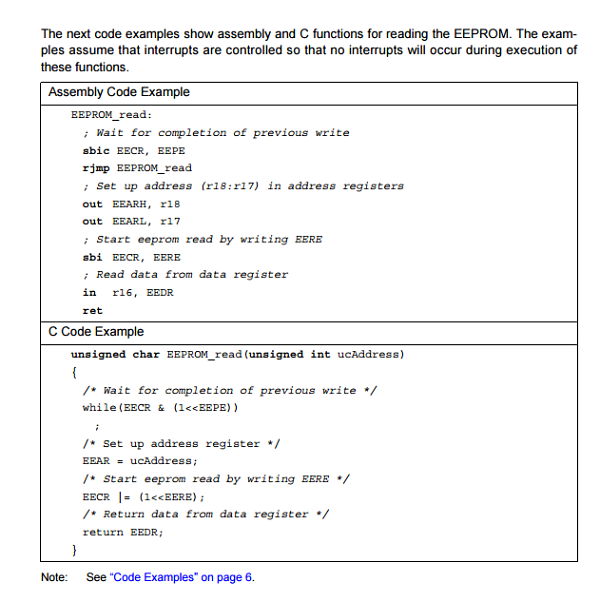
The data sheets were also very helpful as they provided C code for certain parts of the microcontroller. This would be enormously helpful to someone who was looking to write specific code for each application or just a specific application. I was surprised at how much Assembly and C code was provided with most features of the microcontroller.
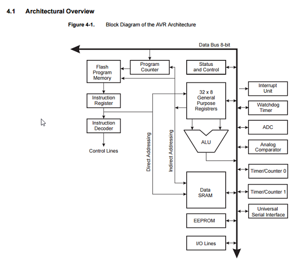
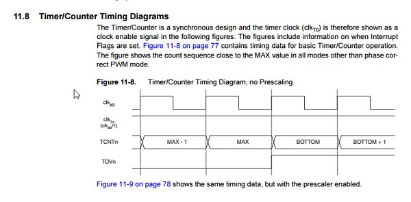
It is also easier to visually represent information in some cases than to write it out. This was glaring when looking at the AVR architecture and the timing diagrams. It was much easier to attempt to understand the information represented visually.
I started by researhing gcc-avr as suggested by Chris, another student in FabAcademy at Lorain. I discovered that gcc-avr is a compiler that takes C language high level code and creates a binary source which can be uploaded into an AVR micro controller. I then read on the Embedded Programming FabAcademy page about C. I started with the tutorial C Learn Code The Hard Way . I then looked at The AVR Libc and the modules, types and math pages.
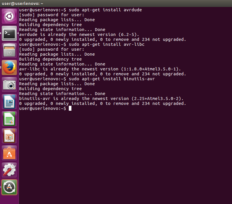
I then installed all the software needed to program in C based upon what I had read on the website. I installed the following using the sudo apt-get install command. I installed avrdude, gcc-avr, binutils-avr, and avr-libr. The gcc-avr is the cross compiler collection. The avrdude is a command line program for reading, writing and manipulating AVRs. The binutils-avr provide the low level utilities needed in building and manipulating object files. The avr-libr files provide similar functions found in a standard C library for specifically the AVR. Needless to say, all of these files are essential in programming the ATTiny44.
I started out working with Chris and Tim in our lab talking about C code. I looked at Neil's examples for his hello.44 project. I learned the process from Scott about how you go from your program file to sending the file to the ATTiny44. I learned it was a multi stage step. My first concern was writing a program to get my board to do something. I needed it to either flash the led or flash the led when I pushed the button. My goal was to write two programs in two different languages to be able to accomplish this goal. I learned that most good code has five steps or elements. They are initialization, input, process, output and termination. This was what I read about in a book on programming with C code and this makes sense from a practical way to approach development of code.
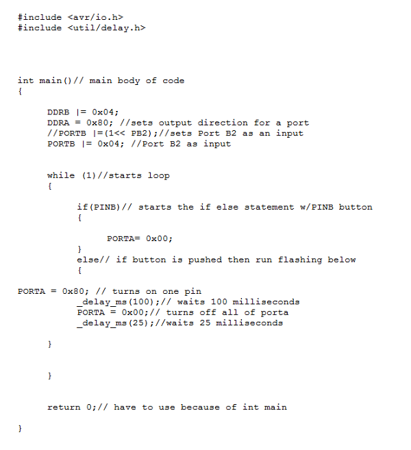
I started by looking at previous examples and opened up gedit in Ubuntu. It was open by default when I opened up other C files so I created a new file. I started with adding the library headers # include
I added my code to define DDRB and DDRA as 0x04 and 0x80. This defines them both as outputs. PORTA defines it as an output. PORTB sets B as input for . PORTA is high at 80 and PORTB is low at 00. Then when PINB is input is pressed the PORTA output will run and turns on the pin, waits 100 milliseconds, turns off, then on for 25 milliseconds then repeats or loops as long as button is depressed.
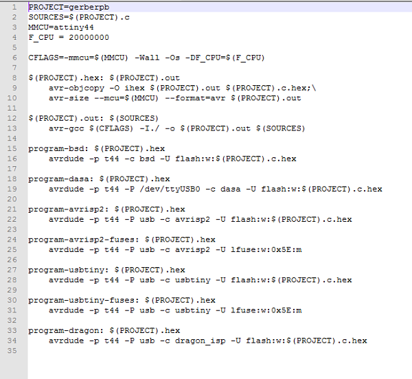
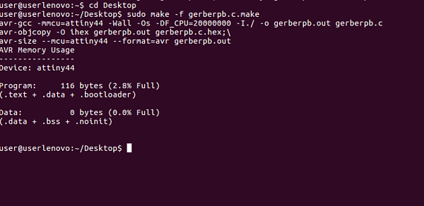
I think the code is completed and I needed to compile with a .make file. I downloaded Neil's Hello44 project and changed his code by replacing his name with mine gerberpb. I then typed in the command: make -f gerberpb.c.make in terminal.
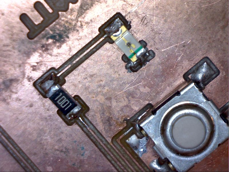
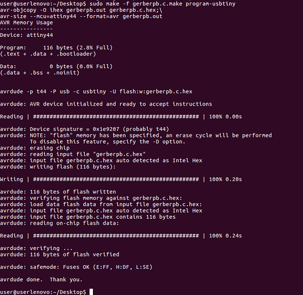
I then typed the command: sudo make -f gerberpb.c make program-usbtiny in the terminal. This sends the hex files to the board. I then pushed the button and found that when I pushed the button it flashed just as programmed and you can see the millisecond difference when it flashes or blinks.
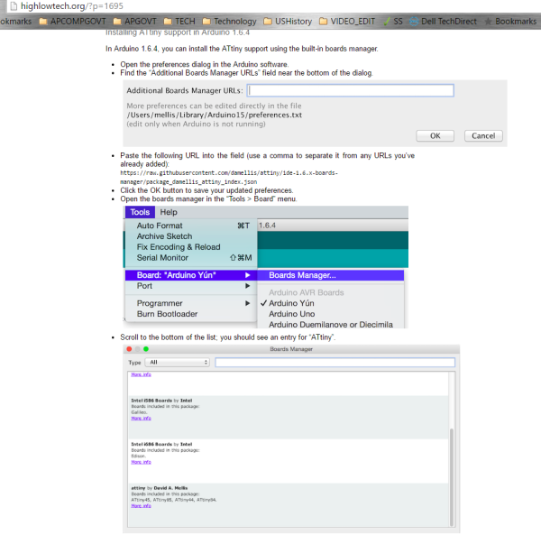
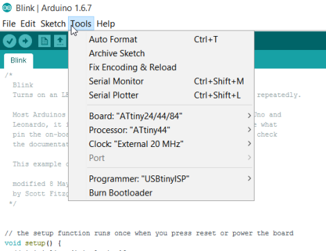
To program in Arduino I had to open up Arduino and go to preferences to install the ATTiny support for Arduino. I ended up reading the instructions for how to do this on HighLow Tech website. This installed the support for ATTiny and then I could go to Tools Board Manager and select the correct board, clock and processor.
It was now time to make the board blink or flash. I opened up the Arduino IDE and started to program. I learned through reading about Arduino vs C that it is very similiar in its setup. In Arduino IDE I looked at the tutorial on blinking for inspiration. It explains the process of how to make it blink. I followed this code for my microprocessor and found that you must have a setup function and loop function. You can see my annotations from the code in the screenshot below.
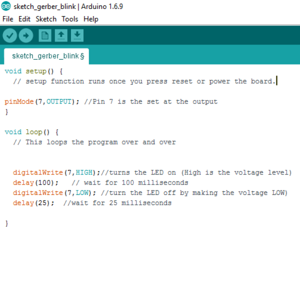
The code was then verified and uploaded to the board. It started blinking and I knew the code was correct.
Project Files: