The assignment for week 4 is to create an in-circuit programmer using the Modela Mill to create the board, stuff the board and then program the in-circuit programmer to create a FabTinyISP (In System Programmer).
After looking over the several designs of the in-circuit programmers, I decided that the model I would follow would be the Zaerc. I decided upon this for several reasons. It was an updated programmer that included a power switch and led, a reset button, led to communicate progress and the USB contacts integrated into the design of the board.
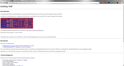
Details and files for Zaerc's FabISP can be found at http://fabacademy.org/archives/2015/doc/FabTinyIsp/index.html
I followed the very detailed instructions on the FabTiny ISP page from the Zaerc link on the Fab Academy website.
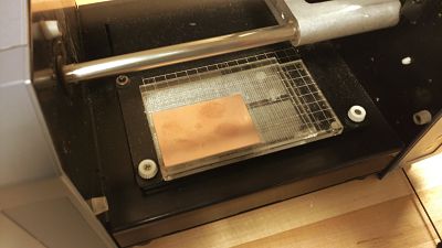
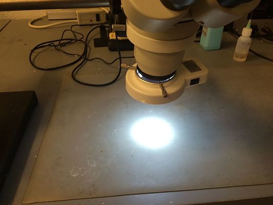
The Modela Mill was used to trace and cut out the board. To start we needed to affix the board to the machine and the sacrificial layer. This can be seen the photo below of the Modela getting ready to cut the Zaerc board out.
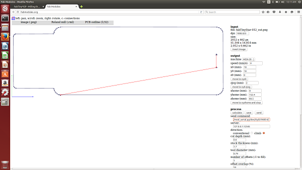
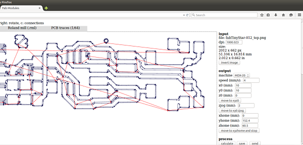
The next step was to use the Fab Modules to get the PCB traces ready for the board to be traced. This interface was easy as it had been set up in the lab previously to be used. The Fab Modules are relatively easy to use in working with the machines. As you can see from the image I am getting the path ready for the PCB board. I loaded the "fabTinyStar-012_top.png" image from the instructions. I then used had the Fab Modules convert it for a toolpath to mill out the board.
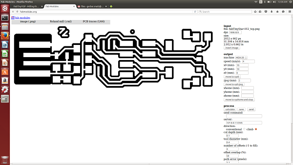
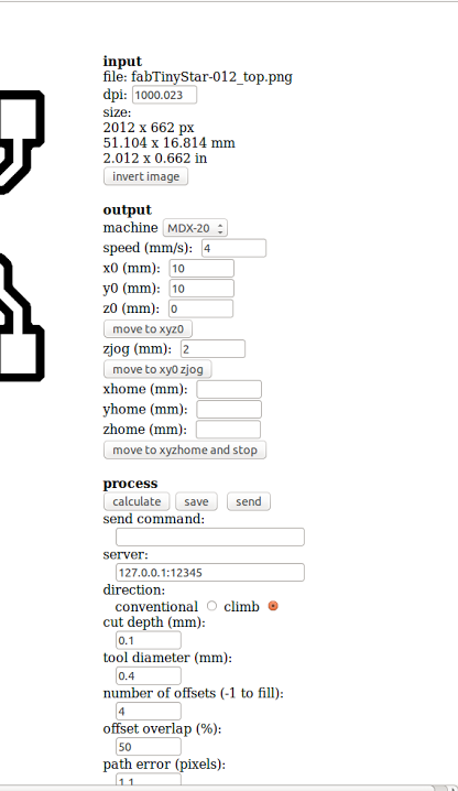
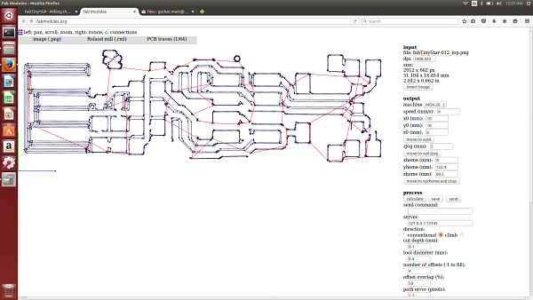
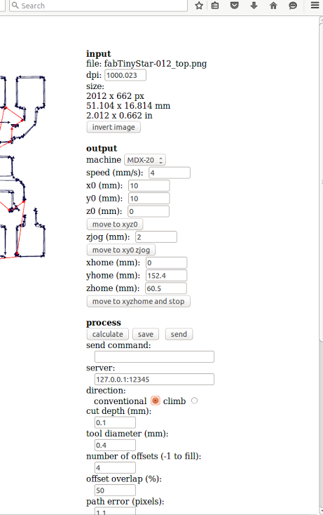
Fab Modules fabTinyStar-012_top.png (Top) | Toolpath and Settings for Zaerc (Bottom)
The board was then milled out using the 1/64" bit.
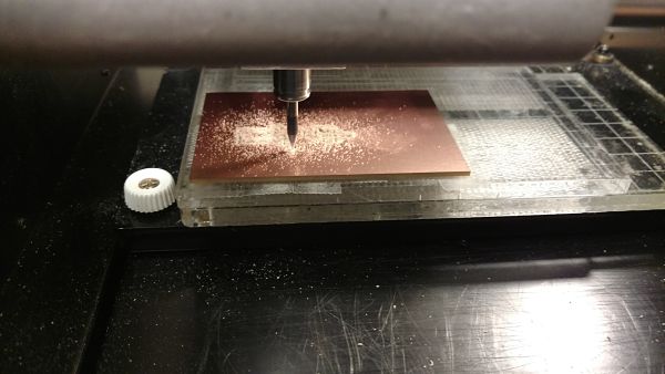
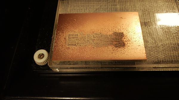
Milling The Board (L) | The Milled Out Board(R)
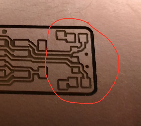
It was then time to cut out the board. This was done in a similar manner using the Fab Modules and loading the correct image. We loaded the "fabTinyStar-012_out.png" and changed the bit to 1/32".
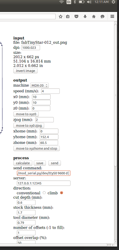
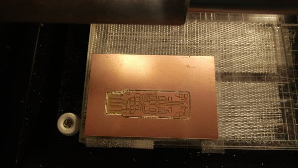
The Loaded "fabTinyStar-012_out.png" (L) | The Cut Out Board(R)
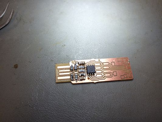
I got everthing cut out and it looked correct and then I realized the default setting on the trace was .40mm and needed to moved to .35mm or the pads would not trace correctly. This was frustrating so I started the process again after I adjusted the settings it produced the correct board. As you can see in the previous pictures the traces for the pads are not complete. The adjustment from .40mm to .35mm worked perfectly and it was time to stuff the board. Luckily, I noticed this prior to stuffing the board.
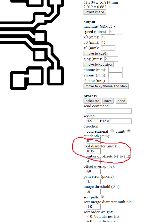
The correct PCB trace and settings (L and M) | The PCB pads correctly milled(R)
The best part of the process the the ability to improve my soldering skills and use the microscope. Chris, from our Fab cohort, helped me learn to tack a component down and provided some tips and hints as to the best techniques for surface mount soldering. He was a great asset to help refresh my skills as to how to surface mount components.
The first step was to assemble alll the components I would need to complete the project and get a map as to how to proceed with soldering the components on the board. I used a print out and then taped each component I would need to a piece of paper. I decided I would solder the board from left to right starting in the top left hand corner with the diodes. Little did I know, these were two of the most difficult to solder down. I found it easier as I moved from left to right and you can see my skills improve as I soldered the board.
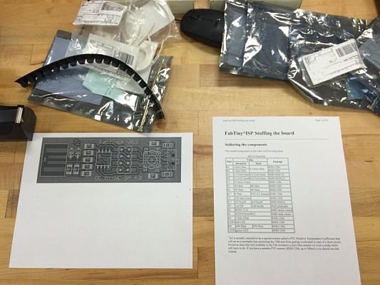
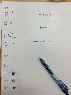
The Board Schematics and Parts List (L) | The Components Listed and Taped Ready to Be Assembled(R)
I started the process by focusing the microscope and learning how to solder using a microscope. I had never soldered components as small as I had to surface mount to the board. Last year I did a lot of soldering but mostly the components were pushed througth the board and soldered on the back of the board. I also had to adjust to soldering looking througth the microscope and I only burned my hand twice.
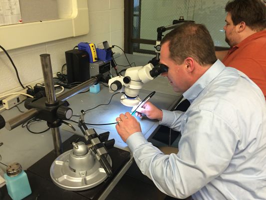
The Microscope (L) | Learning to Surface Mount Solder Using the Microscope(R)
I then started on the top left of the diagram with the Diodes and worked myself from the top left down each column to the end of the board with the final right side and the last solder was LED 2 on the bottom right.
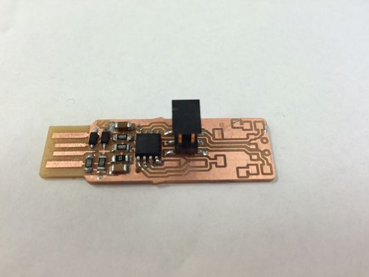
Adding the Components and Stuffing the Board
It was easier as I went along to affix the components to the board. Some of the components were harder to affix to the board, so I used the technique of putting some solder down before attaching the component. This happened for the switch which was probably the most challenging part to solder to the board because of its position. It helps to have professional solder irons. I was used to the $50 solder irons and the professional solder irons make it much easier to solder and control the process. It is not time to program the TinyISP and see if I can get it to work.
I need to use an ISP to turn my TinyISP into a functioning ISP. This seems like an easy process using an Arduino Uno and Ubuntu. I needed to install the latest version of Arduino on my Ubuntu machine and also install AVRDude. We hooked up the Arduino as explained in the directions and were ready to flash the Tiny ISP.
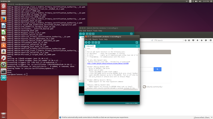
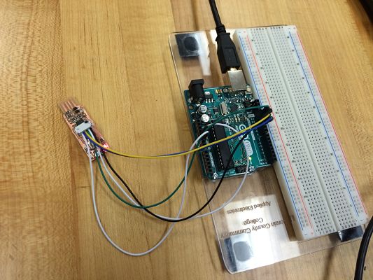
Installing Arduino (L) | The Arduino Set Up To Program The TinyISP
I now needed to program the fuses. I did this by typing in the following command in terminal services.
I then flashed the firmware as part of the instructions. I then ran the "make install" command and it indicated everything was uploaded correctly. I was on to the final step before disabling the fuse. I needed to plug in the the TinyISP and see if it was recognized on my computer.
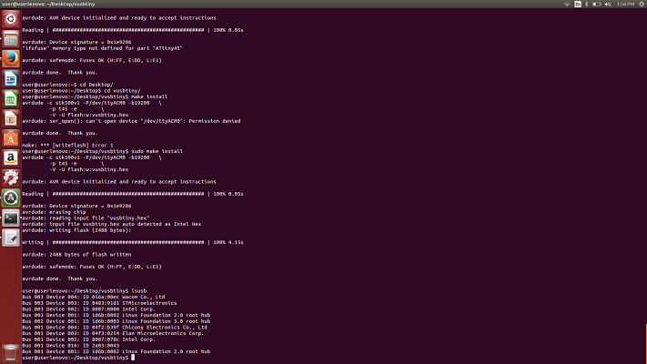
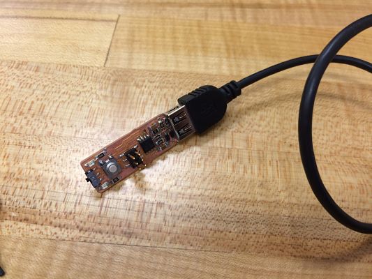
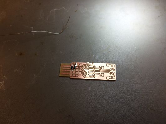
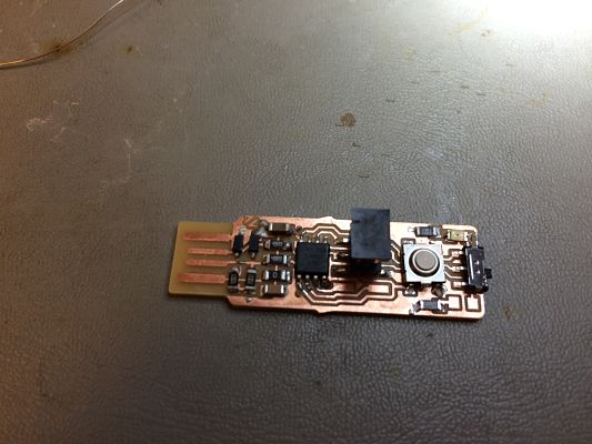
TinyISP Not Recognized (L) | TinyISP attached to USB Cable
I was dismayed that my TinyISP was not showing up on my computer. Everything indicated it was working correctly. I tried several different USB ports, I made a cardboard shim to keep the USB connectors pressed tight and I tried two different computers Windows and Ubuntu, but I could not get my TinyISP to be recognized.
I had several members of my cohort look it over to determine if I had overlooked anything in my troubleshooting. I could not find anything wrong with the board, solder joints and determined that it possibily may be a bad processor. I do not know for sure exactly what is wrong, but I will have to make a new board and get the TinyISP working. It was a great project but frustrating end to the project as I will have to solder a new board and repeat the process to get a working board.
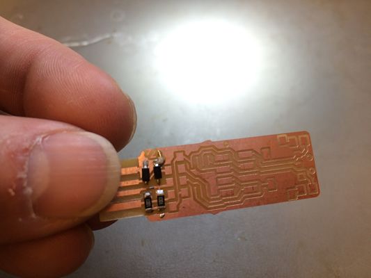
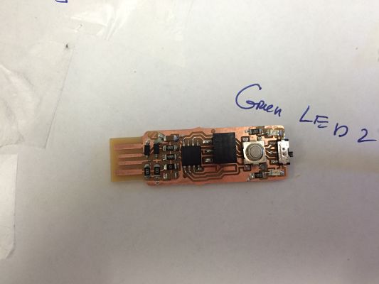
I had the same issues as another member of our group. We both could flash the firmware, but it would not recognize the TinyISP in the computer. We have deduced that it probably was the result of soldering the board diodes first. As a novice solderer, I probably fried the diodes and this would allow for the TinyISP to be flashed, but not recognized on the computer. After remaking the board, I now have a working TinyISP.
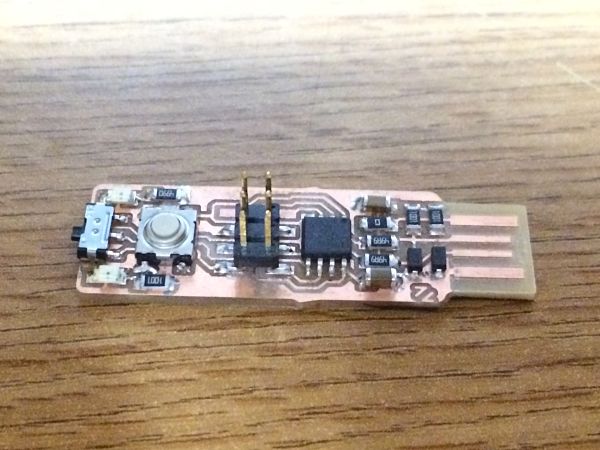
Working TinyISP