The assignment for this week was to design and build a wired&/or wireless network connecting at least two processors.
I will perform the following:
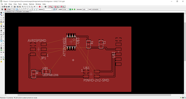
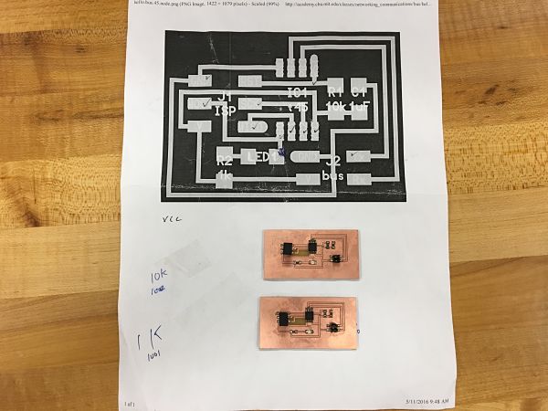
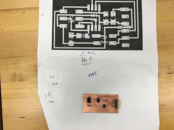
After an interesting lecture on networking by Neil, I opened up Eagle to start the process of designing the board that was sketched out by Neil on the FabAcademy Page. I decided to create the asynchronous serial board. I went to Hello.Bus.45.bridge and Hello.Bus.45.node the to see the board files and what I would need to populate my board and schematics in Eagle. I was planning on creating two node boards and one bridge board. I opened up the Fab Library I had installed in Eagle for the circuit design unit. I was able to add components to my schematics by either command line or using the GUI Add button in Eagle. I like creating several boards at once and my comfortability using Eagle to create schematics and board files has vastly improved.
To create the schematics, I needed the list of components that I needed for the board. Once I secured the components needed I could easily choose the correct component from the fab.lib in Eagle to create the schematic. The components I needed were:
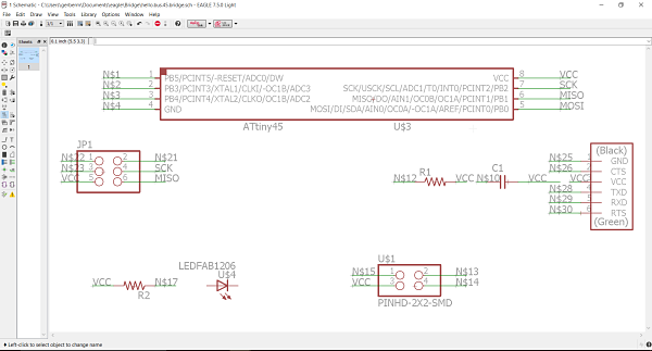
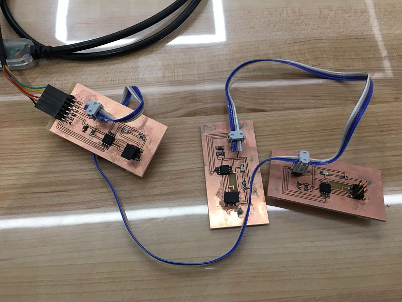
The Bridge Board
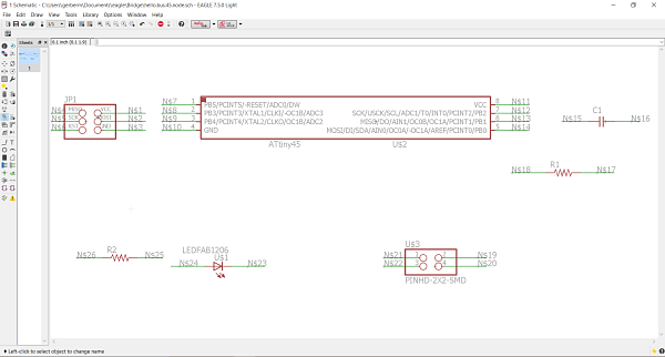
The Node Boards
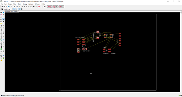
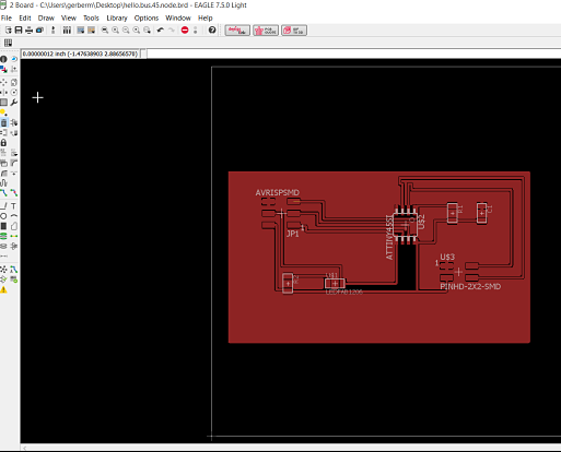
I opened up Eagle and started by creating the Bridge board schematic and then proceeded to create the board files from the schematic. I added the ground plane and the cut lines around the board. I used the ratsnest feature to see the traces that I hand drew and adjusted the view to finest to allow me to draw traces with more granual control. I repeated the process with the node board and worked my way using the diagrams provided by Neil and hand drew each trace. I felt as if the boards were very similar to what was on the diagram. I used the autoroute feature but feel those do not do a good job and I always have issues even at the most complex setting.
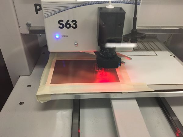
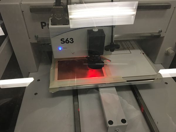
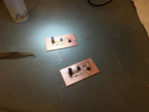
I then proceeded to export the board files to begin the cutting process. It is easy to import the file to the machine and set up the LPKF to mill the boards. I decided to only cut the correct amount of boards. I cut one bridge board and two node boards. I used a 36mm micro cutter .15mm tool to perform the engraving. I used the 38mm 2mm contour routing cutter to cut out the boards on the LPKF. It allows for automatic tool changing during the process. It is a much easier process when cutting the boards.
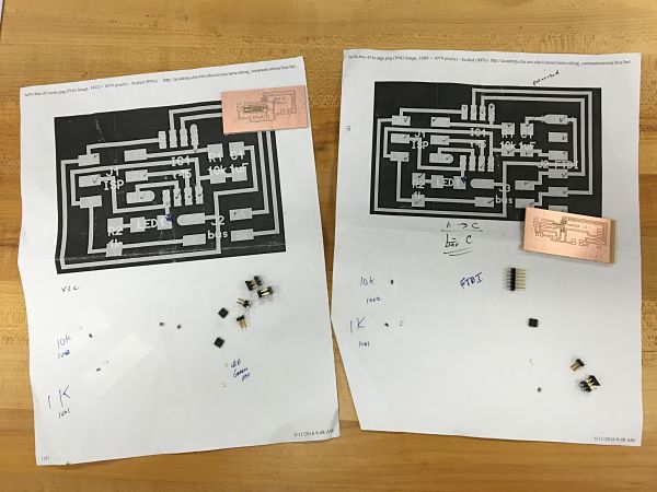
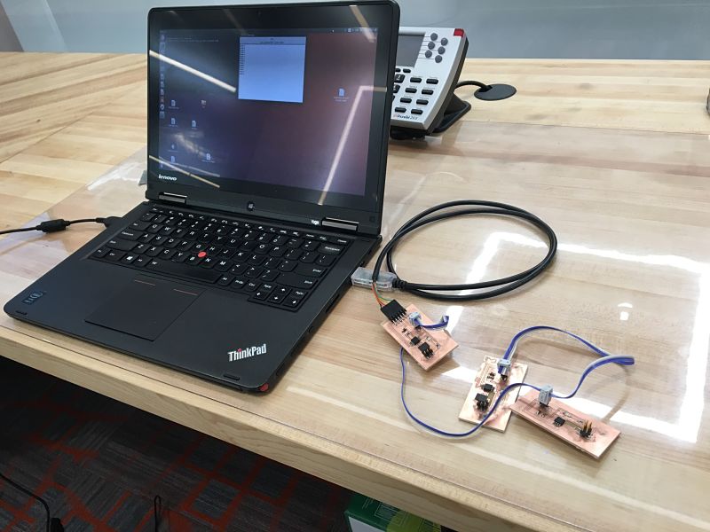
I have really enjoyed the soldering process in FabAcademy. This is the most enjoyable part of the process. I gathered all of my components and taped them down and labeled my papers. These boards are fairly low on components and the process was really easy. I laid out the parts for the three boards and consulted the datasheet for the ATTiny45-SSU and found that dot went to RST on the diagram. I was ready to populate the boards. The amount of time it takes to surface mount has decreased and I can populate a board quickly. I examined the traces and it was time to hook up the boards. I made a serial cable to connect all three boards. I made sure the serial cable was connected to each board correctly. I looked at the schematics diagram and then designated PIN1 to a certain color to make sure they were hooked up correctly. The correct orientation is essential in the communications. It is why you read the data sheet and polarity of the microprocessor. It is the same with the serial cables.
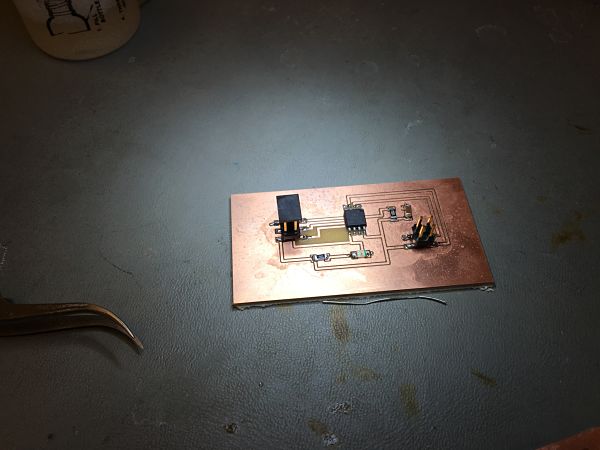
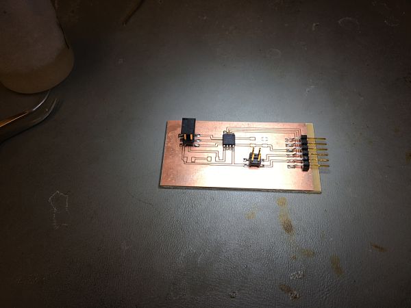
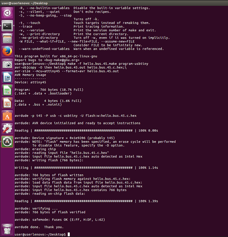
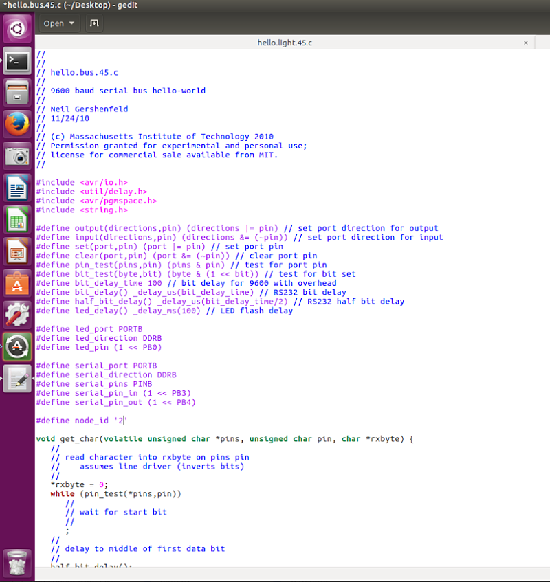
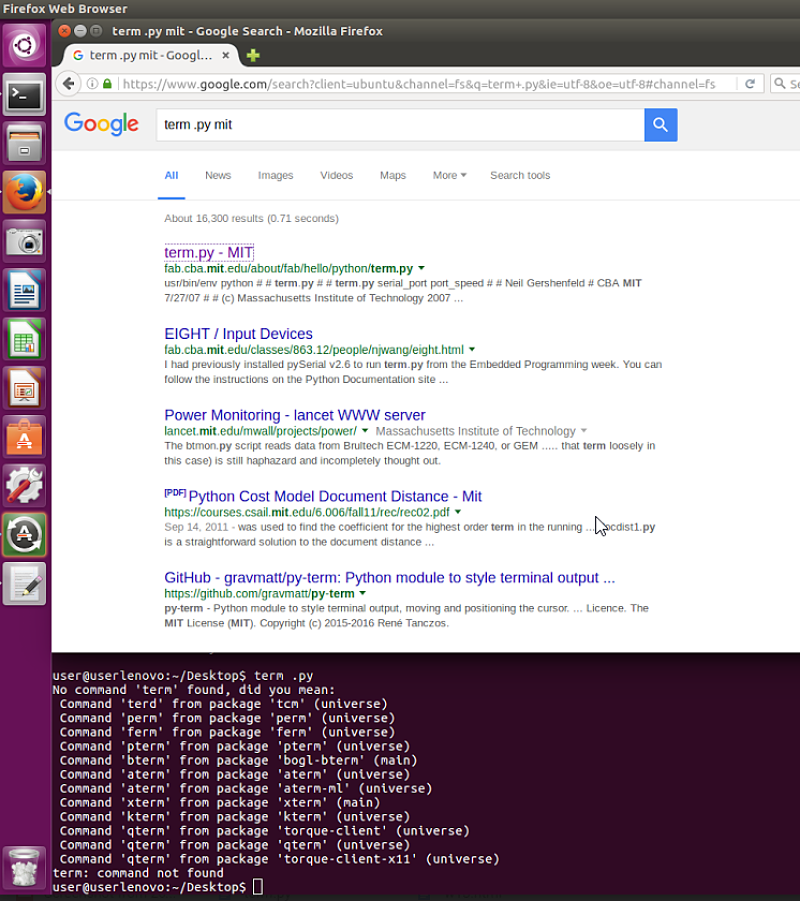
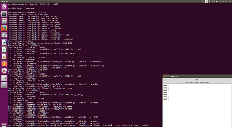
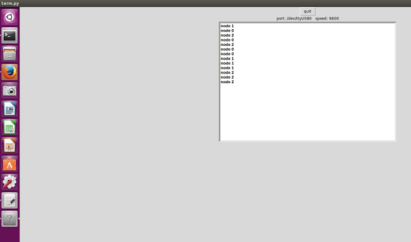
I then needed to flash each board with the make file and C code file. I started with the bridge board and flashed the make files with Terminal line: make -f hello.bus.45.make. I then ran the terminal command: make -f hello.bus.45.make program-usbtiny. I then went into the C file and changed the "#define node_id '0' to #define node_id '1' and reran the process of the make files and c file. I did the same exact process for node board 2 changing it from 1 to 2. After all the boards were flashed and compiled, I made the serial cable and hooked up the boards. I then downloaded term.py on my computer and ran the command: python term.py /dev/ttyUSB0 9600 to open the terminal to send packages to each node. The boards led should flash twice to ensure they were working. I typed in 1 and Node board 1 flashed twice. I repeated this process and each board was flashing correctly. I also ran TERM.PY and it displayed Node 0, Node 1, Node 2 in text to also indicate it responds with text. I was satisfied the boards were communicating based upon the visual flashing and the text displayed in the TERM.PY visual display.
Project Files: