The assignment for this week was to add an output device to a microcontroller board I designed and program it to do something.
I will perform the following:
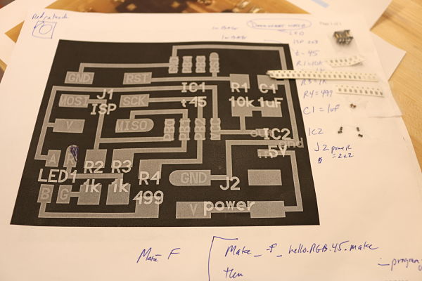
I opened up Eagle to start the process of designing the board that was sketched out by Neil on the FabAcademy Page. I went to Hello.RGB.45 to see the board files and what I would need to populate my board and schematics in Eagle. I opened up the Fab Library I had installed in Eagle for the circuit design unit. I was able to add components to my schematics by either command line or using the GUI Add button in Eagle. Everything is getting faster as the more boards I build the more confident I am using Eagle the the process behind creating a PCB. The short layoff between the Input Devices unit and the Output has made it easier to remember all the steps in the process of designing a board. The amount of time involved and confidence in understanding the basics has increased with each board I complete.
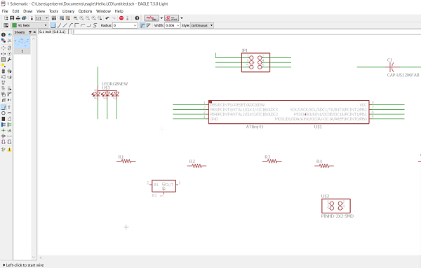
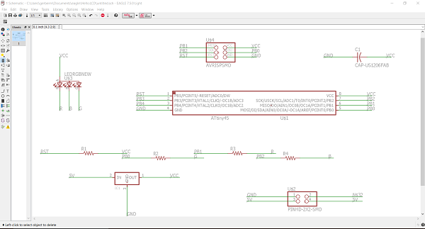
To create the schematics, I needed the list of components that I needed for the board. Once I secured the components needed I could easily choose the correct component from the fab.lib in Eagle to create the schematic. The components I needed were:
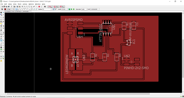
I started by entering Eagle and worked through the schematic. It was much faster as I was more comfortable creating labels, wires and using the Fab Library. I quickly populated the board based upon the RGB files on the Fab Academy page. I was confident I had created the and labelled everythign correctly. It was time to consult the drawings to make sure it was populated correctly. I felt confident it was correct.
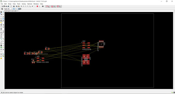
I then proceeded to convert the schematic to a board file. This again was much smoother as I remembered how to do this from the Input week.
The next phase was to place all the above mentioned components on the board. I consulted Neil's board to see how he populated his board and tried to line mine up in a similar fashion. I moved over to board view and started dragging the components over and placing them. The RGB Led board is fairly straightforward in its layout. It was a simple task to drag it over. I did have a few times when I needed to rotate parts to create easier paths and traces. I also added a ground plane. This makes the grounding much easier. It was a quick process and I was off to cutting out the boards.
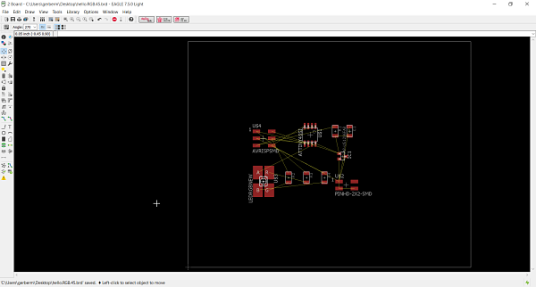
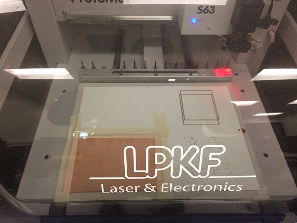
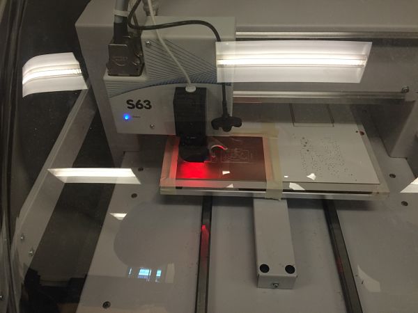
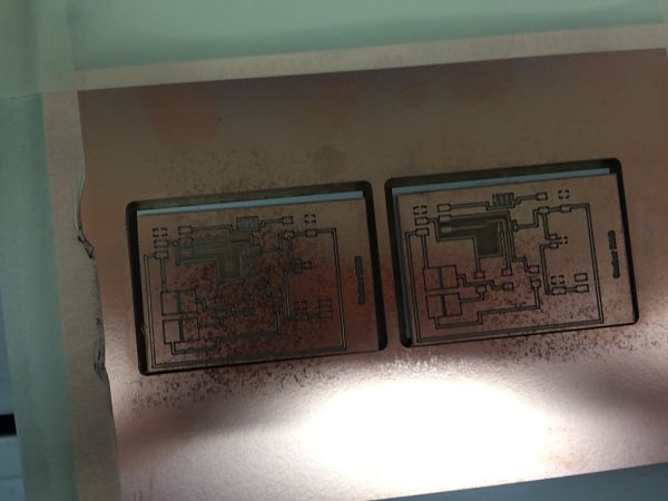
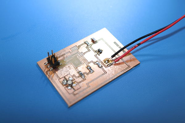
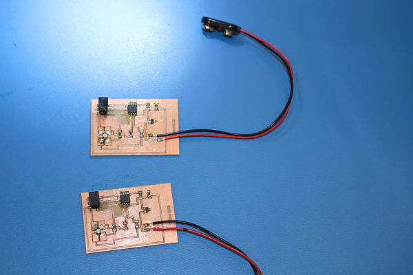
I then proceeded to export the board files to begin the cutting process. It is easy to import the file to the machine and set up the LPKF to mill the boards. I have been also experimenting using the Othermill to cut a few PCB's as well. The LPKF does a better job at the moment. I also still am cutting two boards when I make a board. I solder both boards and this prevents against failure, unless it is a poor design. This time I needed both boards (or so I thought) and was glad I cut both boards. I also engraved my name on the board with the RGB name to identify the board.
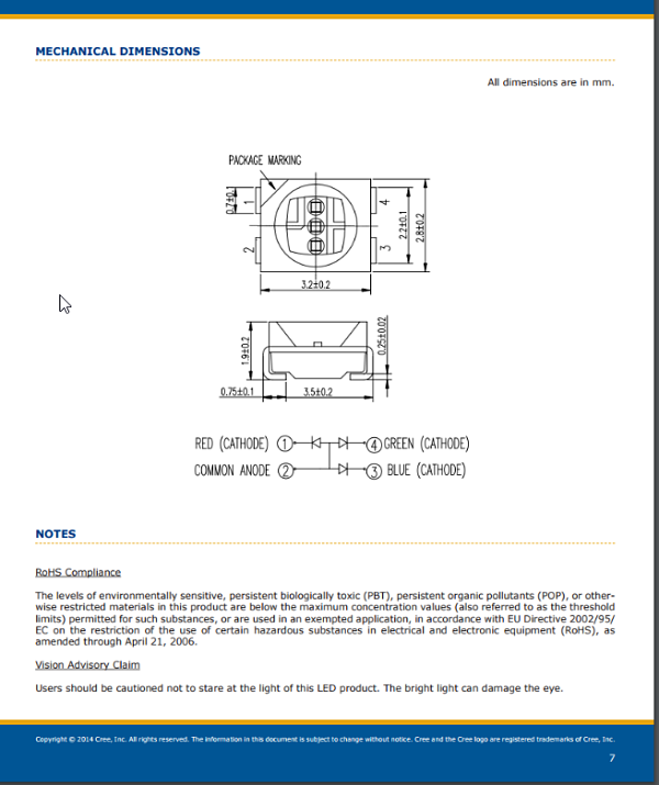
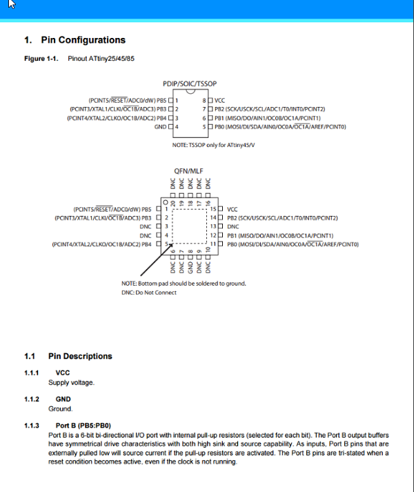
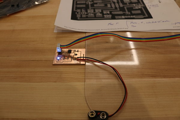
I then took the components and populated the board. This is the most enjoyable part of the process to me. I find it relaxing to solder and enjoy the challenge of small parts. This was no different. I first assembled the materials that would be needed. I taped them to the piece of paper that I printed out with Neil's board diagram. I wrote notes on the paper and even consulted TWO data sheets. I had to look at the RGB data sheet to ensure I was putting the RGB in the right place. I looked at the notch and made sure I placed it over the RED contact on the board. I also needed to look at the ATTiny45-SSU data sheet to see where the dot went. I learned by looking at the datasheet it was to be on the RST on my board. The datasheets are extremely helpful as I populated the board. I also learned that soldering the ATTiny45-SSU microprocessor is a real pain. I pulled up part of the trace as I soldered the board. I tried to fix it but was unsure if my contacts were going to hold or were connecting. I also had some trouble with the RGB as I was not sure the contacts, which are located under the part, were difficult to solder. I used the microscope as I soldered to make sure all my contacts and traces were good. I actually soldered two boards at a time. I populated one board and then went back and soldered the second board.
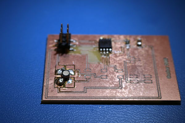
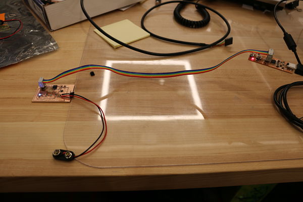
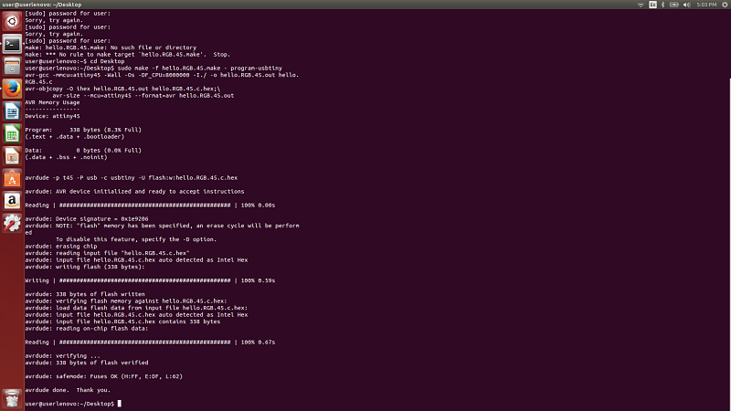
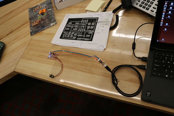
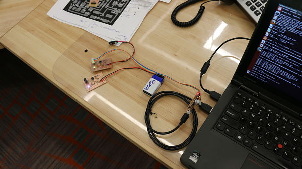
I then flashed and compiled the program files on my board and everthing seemed to work. I downloaded all the files from the FabAcademy site to my desktop on Ubuntu. The files I downloaded to the desktop were: hello.RGB.45.c and the makefile. I placed both of these files on my desktop and then ran the command: sudo make -f hello.RGB.45.make - program-usbtiny. This flashed the board and copied the files hello.RGB.45.out and hello.RGB.45.c.hex. After I ran this command, the RGB Led began to flash and turn different colors. I repeated this step with my other board and it worked exactly as the first. I was excited because this was the first board that I created that worked with no issues in soldering, design, programmign or cooked components. It was a great feeling to create the board and finally begin to understand and feel comfortable with the process. I was concerned because of the trace I pulled up on the microprocessor on one board and the LED not quite touching and fixing the other board. I must have corrected each board because they both worked exactly as they should.
I did not alter the code that Neil had written as my pins and board layout was exactly the same as Neil's. I did open the hello.RGB.45.c file and look at what the code did. I noticed that is was similar in its nature to the C code. The beginning of the code included the Avr/io.h and util/delay.h libraries. The AVR IO library header code helps with IO definitions. The util/delay.h header library are basic busy/wait functions. Both of these are extremely important to the hello.RGB.45.c file. Then it was defined certain #define directives. This instructs the compiler to replace all successive occurrences of identifier with definition. For example, in the code #define led_port PORTB is in the code always led_port will always be PORTB. It then defines the color and the Port and the bit of the Port associated with Red (PB1), Green (PB0), and Blue (PB2). The code then includes the necessary int main, this is the point where the programming turns to execution. The code sets the clock divider with CLKPR, initializes the LED pins and then loops throught red, green and blue. This is the simple, yet complex code for the board. The ++pwm is what causes the led to look like it fades in and out based upon the <255 portion of the code in each color. The fading or pulsing of colors is the pwm or pulse width modulation.
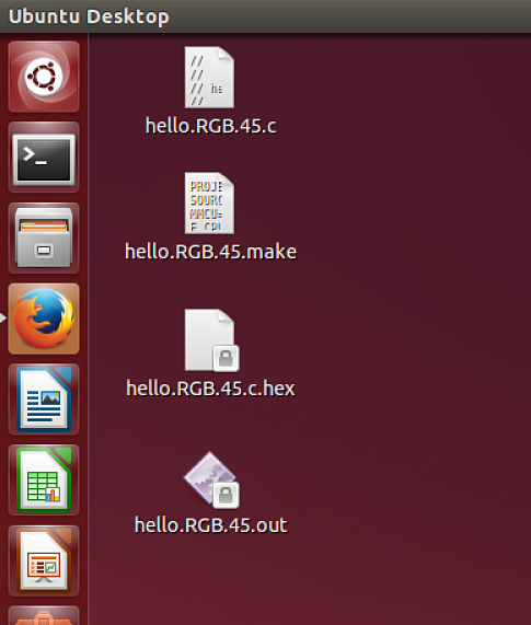
Project Files: