In the eighth week we explore Embedded Programming. We will take the PCBs we created in week #4 and program them to do something.
The sample program I used can turn on the LED and set the on time and off time. I will also experiment with a program that enables the PCB to have an LED light when a pushbutton is pressed.
Here is a list of tasks as I see them for the eighth week.
I downloaded the ATtiny4a data sheet and scanned through a lot of it. Page #2, the pinout configuration of the ATtiny44a was helpful.
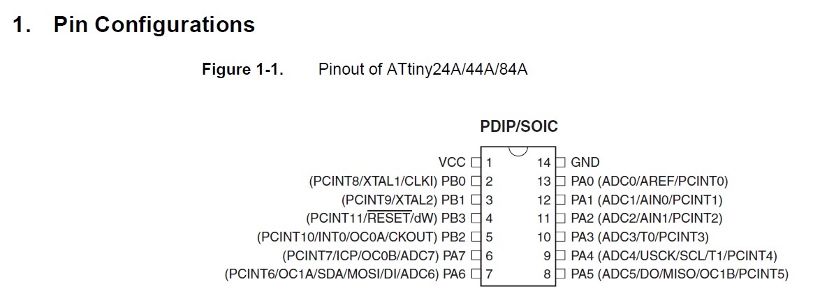
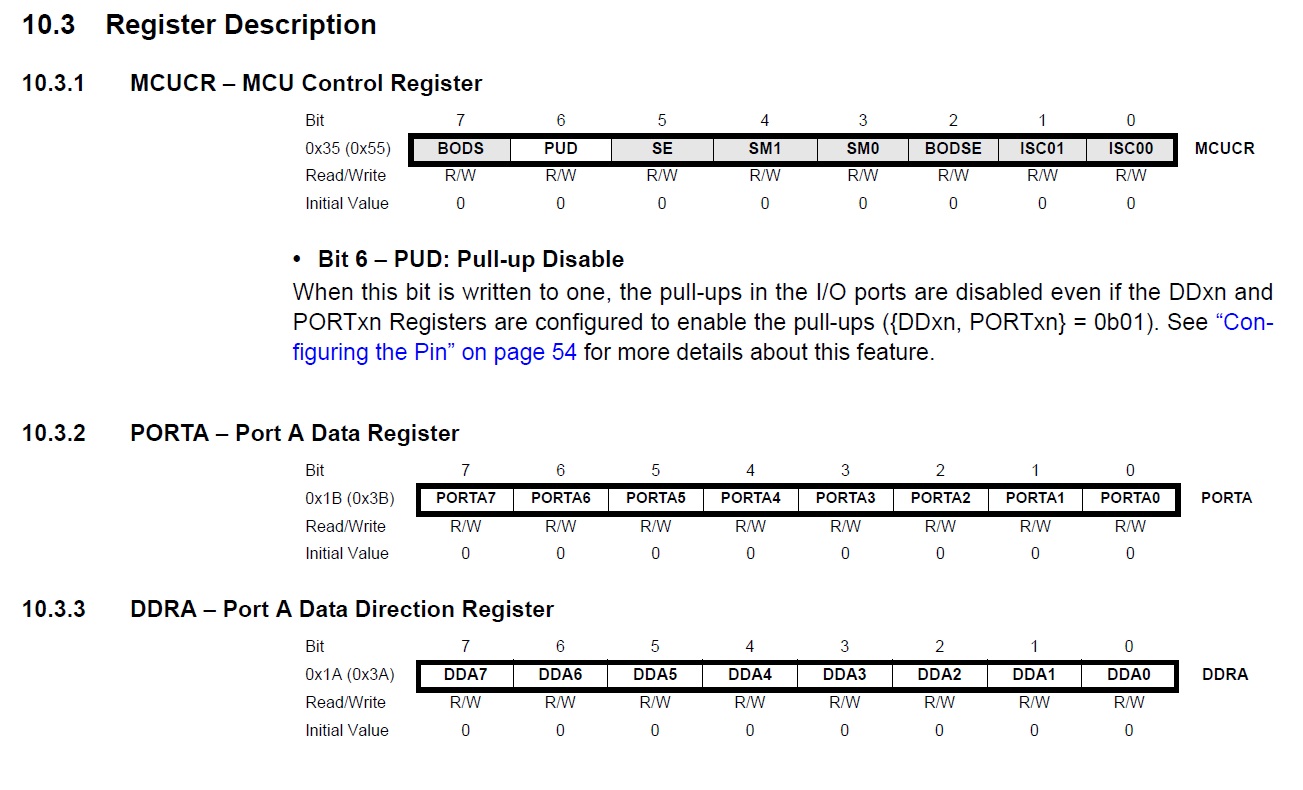
Pages 66 & 67 which showed the register description also helped. I needed the pinouts to find pin PA7.
I used the register description for DDRA to control the blinking lights and the pushbutton circuit.
I spent quite a bit of time trying to understand some of the codes used in "C" programming. I found a basic description in Wikipedia. Dennis Ritchie and Bell labs developed the code in the early 70's.
The article also included some descriptions of codes used in programming, mostly operators. I found I needed much more information than was found in the Wiki. I then looked into tuturials for help.
I scanned the one by Alex
Allain. It was helpful to some extent.
One other need I had was to refresh my comand of "Bash" commands. I
found an "A to Z" index of bash commands at http://ss64.com/bash/
My next attempt was to download some recommended compilers and librarys. The command I used was "sudo apt-get install avrdude".
I then used the same command to load; "avr-libc", binutils-avr", and "gcc-avr". I now had the files I needed to play with some samples.
I had two programs to play with. test.c and button.c At first I just tried substituting some of the values to see how they would affect the programming.
I was not having much luck. After some counseling and some more experimentation I was able understand the process.
I created a little flow chart that helps me to remember the steps I need. I know I am only substituting a few codes but I feel a liitle better about it.
Here is the flow chart I came up with.
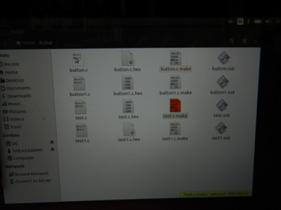
Here is a screen image of some of the files I downloaded.
I choose to edit a program with a delay in it. Note the red colored text in "test.c". The delay is currently 50 ms.
test.c
#include
<avr/io.h>
// this includes the
infromation about the avr atmel micros
#include
<util/delay.h> // delay header
int
main() // main
function must have
{//
this
bracket opens main
//DDRB = 0x04;
DDRA = 0x80; //
sets the data direction register for port a
or PA7 it is bitwise set
while (1) // starts a while loop
in this case it is a forever loop
{// anything between here and
the other bracket is in the loop.
PORTA = 0x80; //
turns on one pin
_delay_ms(50);//
waits
PORTA = 0x00;//
turns off all of porta
_delay_ms(50);//waits
}
return 0;// need this becuase of
int main
} // this bracket closes main
test1.c
#include
<avr/io.h>
// this includes the
infromation about the avr atmel micros
#include
<util/delay.h> // delay header
int
main() // main
function must have
{//
this
bracket opens main
//DDRB = 0x04;
DDRA = 0x80; //
sets the data dirction register for port a
or PA7 it is bitwise set
CLKPR = (1 << CLKPCE);
CLKPR = (0
<< CLKPS3) | (0 <<
CLKPS2) | (0 << CLKPS1) | (0 << CLKPS0);
while (1) // starts a while loop
in this case it is a forever loop
{// anything between here and
the other bracket is in the loop.
PORTA = 0x80; //
turns on one pin
_delay_ms(1000);//
waits
PORTA = 0x00;//
turns off all of porta
_delay_ms(1000);//waits
}
return 0;// need this becuase of
int main
} // this bracket closes main
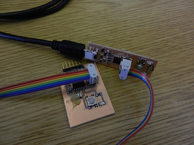
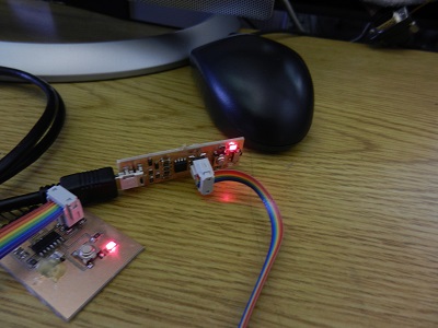
Here is an image of the PCB boards connected.
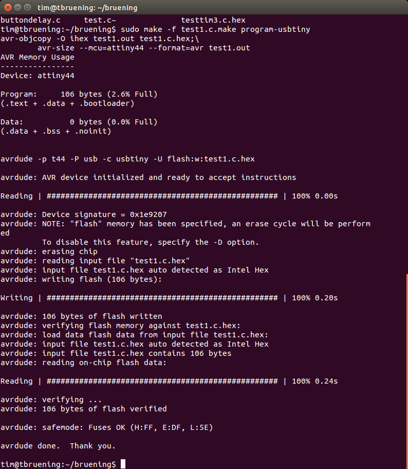
Here is a screen shot sending test1.c to the attiny44a.
Here is a screen shot of the circuit working.
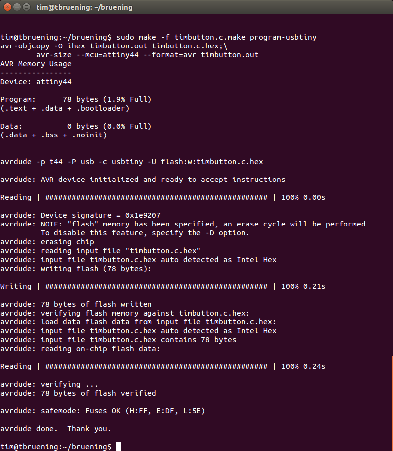
Here is a screen shot sending timbutton.c to the attiny44a.
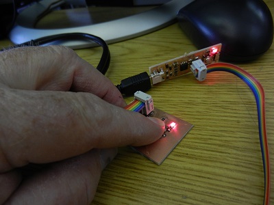
Here is a picture showing the push button working.
I definitely had to work hard to complete this assignment. I am still quite the rookie when it comes to "C" programming.
My biggest problem was rememberig the sequences I needed to take to edit the file, compile the file, then run the file to see the delay.