In the third week we looked at
Computer Controlled
Cutting. Many machines today use some form of computer
controlled
cutting for production. There are CNC lathes and mills, CNC
sewing machines, CNC lasers and plasma cutters, vinyl cutters and
others. Once a digital file is created it is a simple process
to
generate code for a computer contolled cutting machine.
Here is a list of tasks as I see them for the third week.
In a parametric model many parts
or features are
identical. It is much
easier to create one master feature and use it to control the
properties of the other features or parts. Change the
dinension
in the
master part and all other identical parts are change at the same
time.
Much easier than editing each and every one.
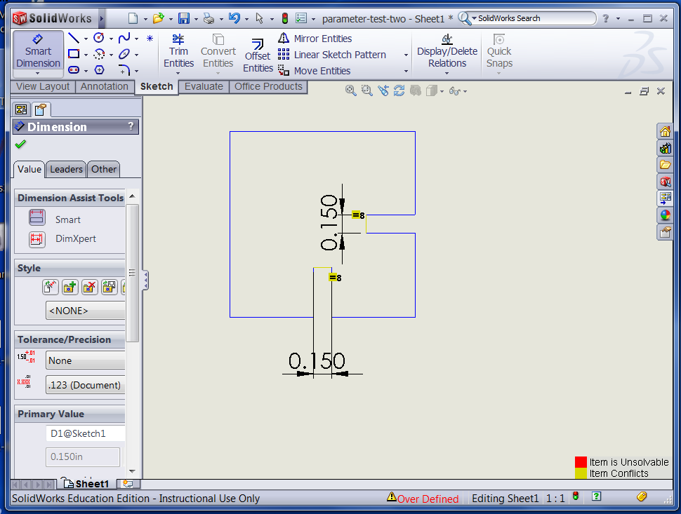
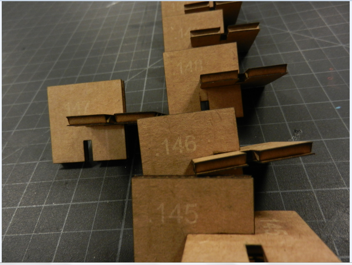
I first created a test part to gauge what size slot worked with the cardboard I was using. For practice I made a parametric relationship between the two slots in the sample. I then edited the drawing and created .dxf files for the test pieces. The sizes of the slots on the drawing ranged from .145" to .152" I chose .147" as the best fit for my design.
Here is a screenshot of a solidWorks drawing showing the sample parametric part.
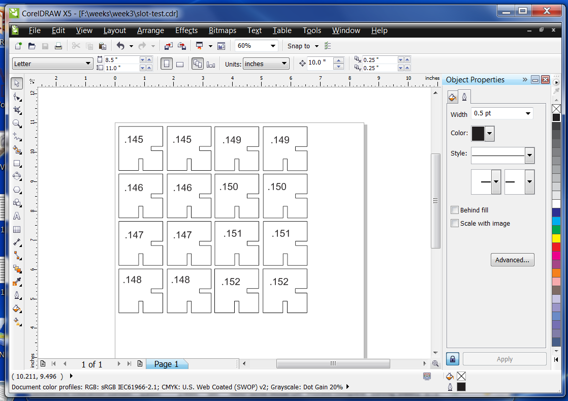
Here is a Corel screenshot of the sample piece drawings.
I am cutting pieces with different size slots to see how the laser cuts them.
The width of the "kerf", or slot cut by the laser has to be allowed in your calculations.
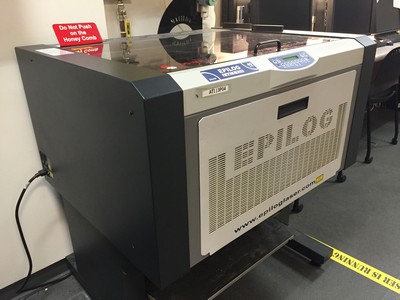
Here is a picture of the laser I will use to cut the cardboard pieces. This is an Epilog Mini - 18 x 24 40 watt laser.
Maximum size of material is 18 inches by 24 inches. Power rating is 40 watts.
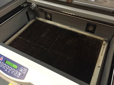
Here is a picture of the inside of the laser. We currently have a honey-comb plate installed for vector cutting.
A laser is capable of either raster or vector cutting. Raster cutting merely engrave the surface.
Vector cutting can cut through the part. In order to vector cut the iamge must a true vector line. No bitmaps will vector cut.
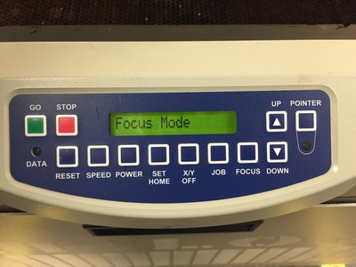
Here is a view of the laser control panel. The first thing that has to be done is to focus the laser.
All lasers have a "Focal Point" that is a set distance between the laser head and the top of the material.
The Epilog laser has the ability to either Auto-focus or Manual-focus. For this project I will use manual focus.
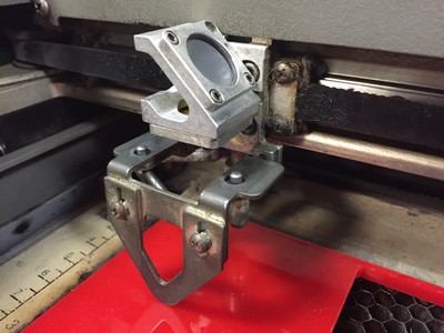
When the focus button is pressed on the control panel, the laser head moves to a set position.
If this position does not work due to size or heigh problems the laser head can be unlocked and moved to another position.
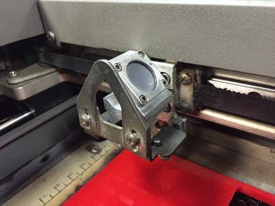
Once in position, the probe that is usually magnetically attached in the upside down position, is attached in the downward position.
Using the control panel the machine bed is raised until it touches the probe. After touching off the probe is put back in the upside down position.
The last part of focusing is to push the reset button on the control panel This returns the laser head to the origin and lasering may begin.
After focusing we can send a file to the laser. Using a laser is very similar to printing on a computer.
The file is sent and the laser will due the work. If the laser sees a vector line it wil want to cut through the material.
If it sees anything other than a vector line it will want to raster the image. A raster image is similar to the old Dot-matrix printers.
The laser keeps goint back and forth firing the laser every time it sees a pixel on the image.
The laser has three pieces of information it needs for settings. Speed, power and frequency. For raster we only need speed and power.
The basic values for these settings will come with the machine. Over time and experimentation other materials, thicknesses or variations will be discovered.
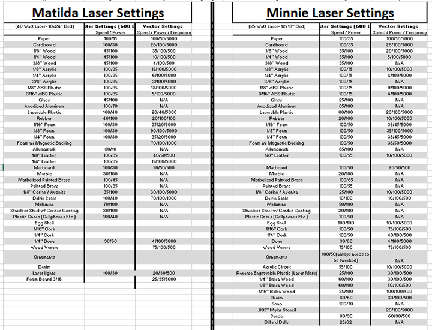
The following is the spreadsheet we developed over the last 10 years through our experiences with different materials.
NOTE: Some materials cannot be cut on a laser. PVC or anything with vinyl are definetely out.
Make sure to check with the manufacturer of your laser for info particular to your laser.
In our lab Matilda is our 40 watt laser and Minnie is our 12" x 18" 25 watt laser.
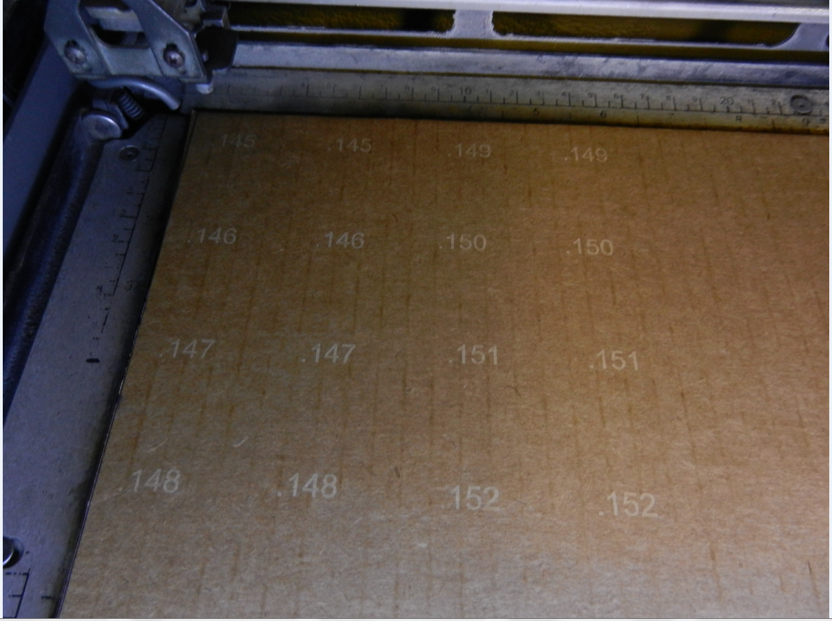
Here is a photo of the numbers etched by the laser.
I used a speed setting of 100 and a power setting of 30 to raster engrave the numbers on the test parts
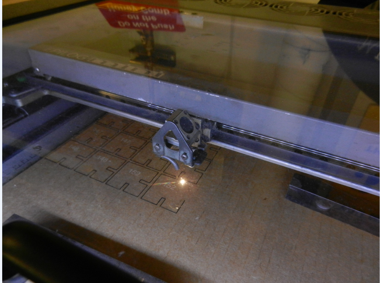
Here is a photo showing the laser cutting out the samples.
I used a speed setting of 26, a power setting of 100 and a frequency of 5000 to vector cut the parts.
Here is a screenshot of the assembled samples. I decided that .147" would work the best.
For this project I went to a project I
started a few
years ago but did not finish. I had downloaded a plan for a
geodesic dome from "hilaroad.com" and started to create the files
needed for construction. I got busy with other things and
never
continued. I figured it would be a good project for
parametrics. The design consisted of two triangles, one
isosceles
and one equalateral. One side of the isosceles triangle was
equal
to each of the three sides of the equalateral triangle. I
would
let the one side of the isosceles triangle drive the lengths of the
other.
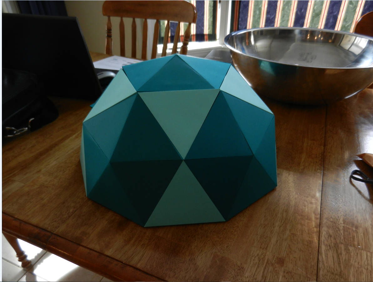
I finished my original design and created a small geodesic
dome out of
cardstock. The design called for tabs instead of
slots.
Using small binder clips I connected the parts together. I
needed
about six other hands to do this. I decided that a minimum of
two
binder clips per side was needed.
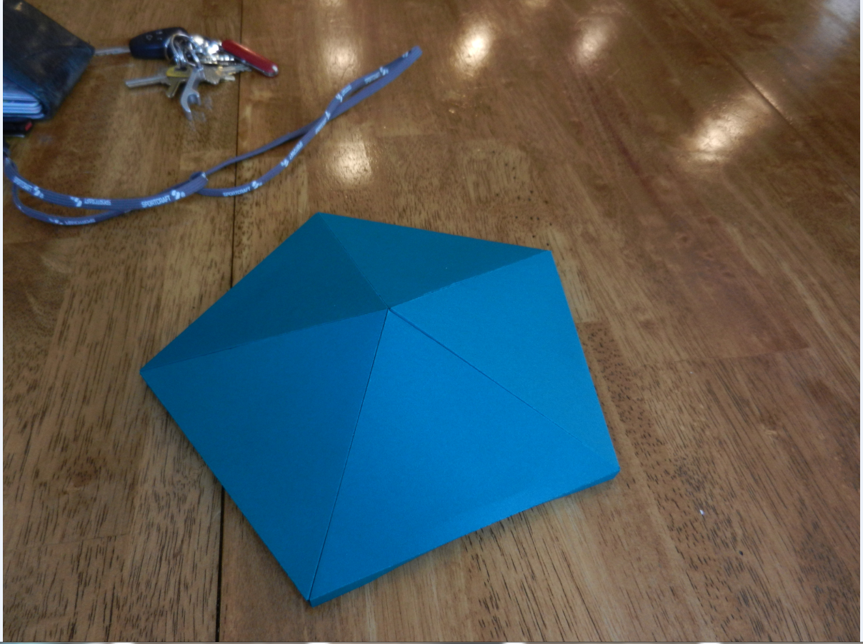
Here is a photo of a single assembled paper pentagon
 file:///G:/weeks/week3/slot-test.cdr
Here is a photo of a finished dome
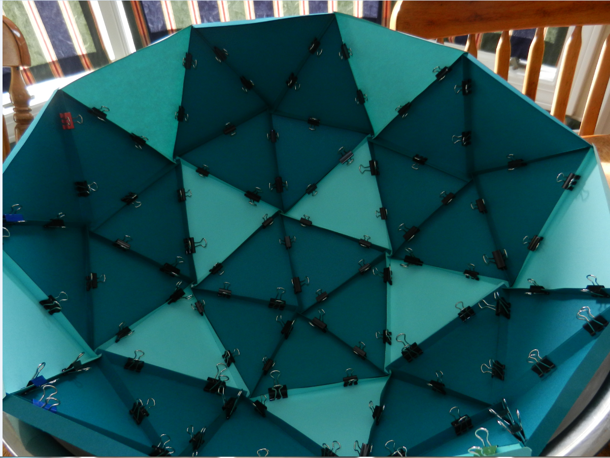
Here is a photo of the underside of the dome showing double clips for strength.
I then created my files for the cardboard version of the dome using SolidWorks. I created the drawing for the two triangles. The drawing included a slot drawn separately with a parametric relationship to control the others. The lengths of the equal sides were also cotroled parametrically. I had quite a few problems getting the drawings to show the parametrics I wanted. Every time I edited the drawing it seemed that I changed some relationship between parts. The more I got into the SolidWorks the better choices I made.
I then saved the drawing file in .dxf format. Using CorelDraw
I
imported the .dxf file and prepared for cutting on the laser.
I
needed 30 of the isosceles and 10 of the equalateral
triangles. 6
sets of 5 isosceles triangles were assemble to create
pentagons.
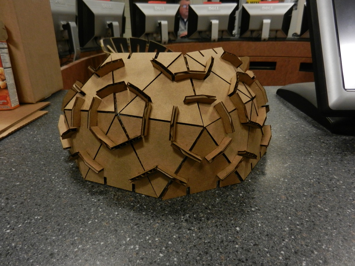
The pentagons were then connected with equalateral triangles to form
the finished dome. I assembled about half of a dome.
Here is a phote of a pentagon using a 10 degree included angles.
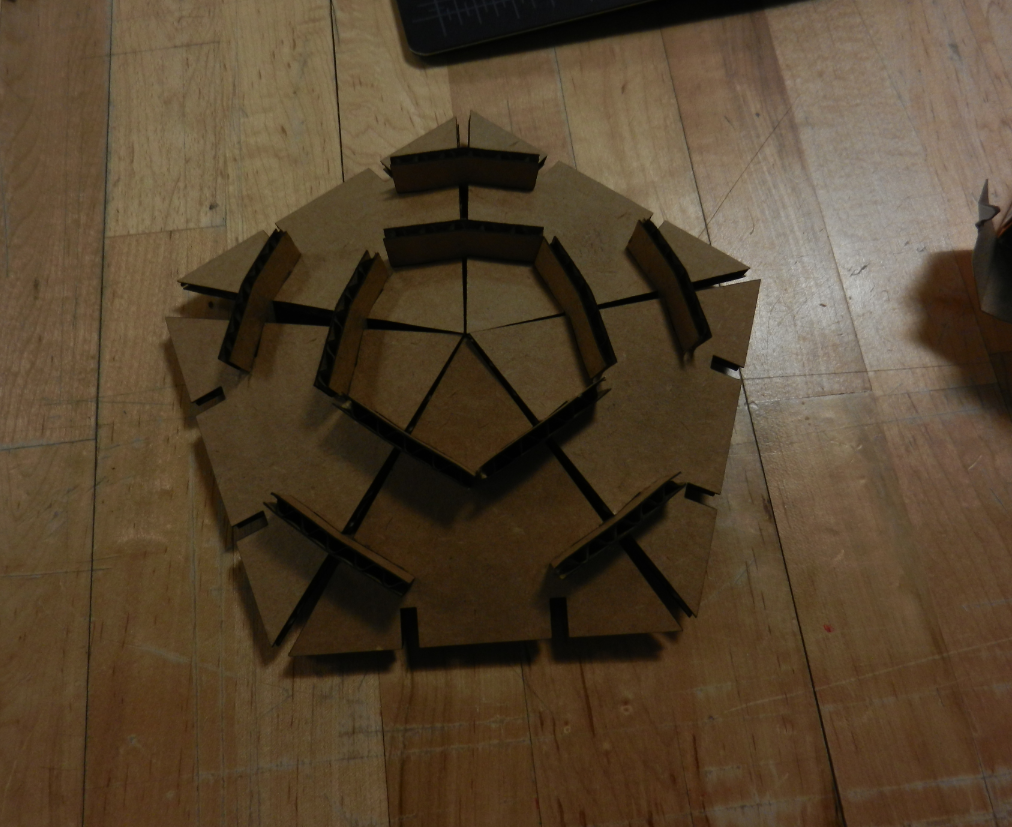
Here is a photo of a pentagon using a 15 degree included angles.
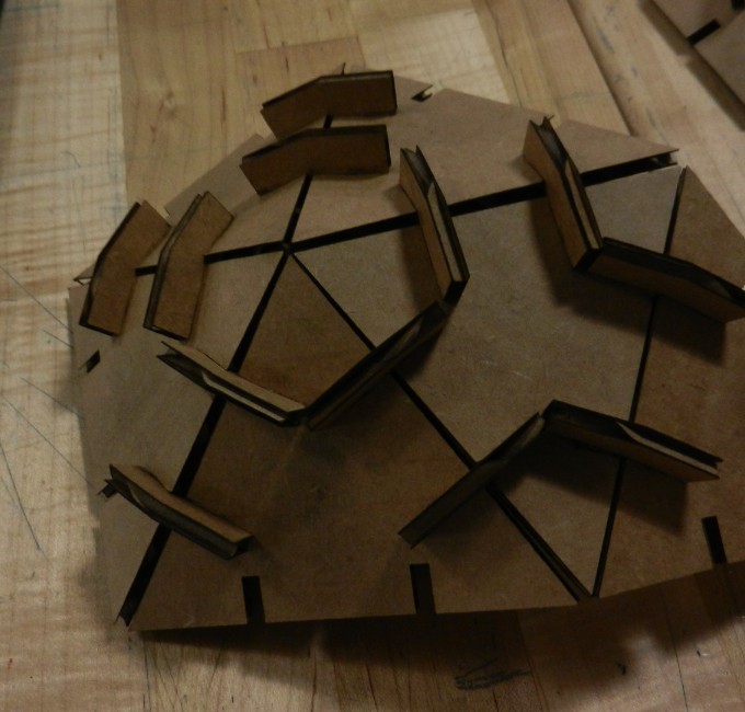
Here is a phote of the mostly completed part.
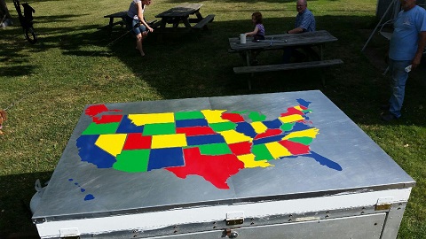
Here is a United States map I created using the vinyl cutter.
My son is on a 27 day trip around the United States and wanted to put a vinyl image on top of a small traier.
This is the image we came up with. We needed some contrast to make it easier to see the individual states.
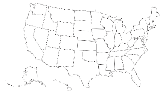
Here is the original outline of the US that I used.
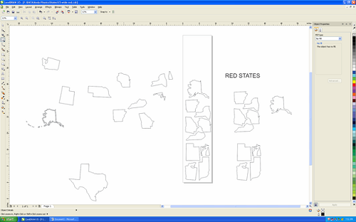
Here is a Corel draw image of the red states.
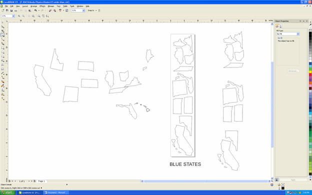
Here is the Corel draw image of the blue states.
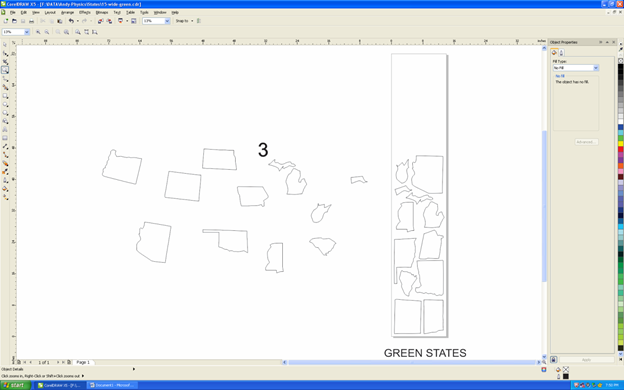
Here is the Corel draw image of the green states.
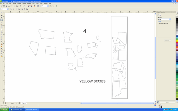
Here is the Corel draw image of the yellow states.
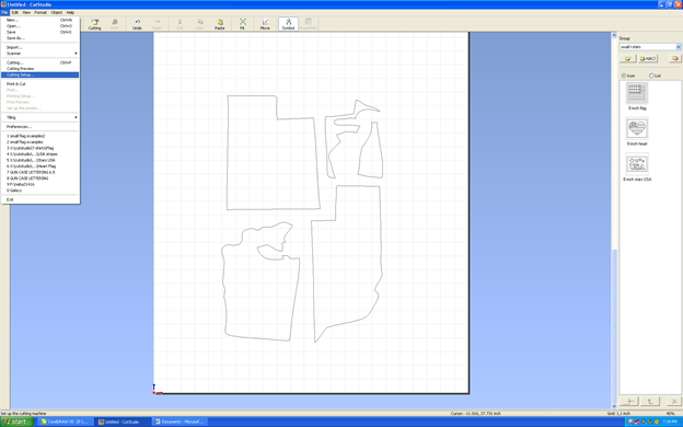
Here is the process I used to cut out the shaoes in vinyl. I am only showing 4 states but the process is identical.
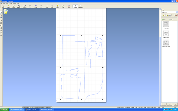
I copied the drawings in Corel draw. I then pasted it into Cut Studio, the software for our Roland vinyl ccutter.
The next thing to do is set up the material.
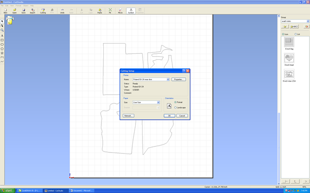
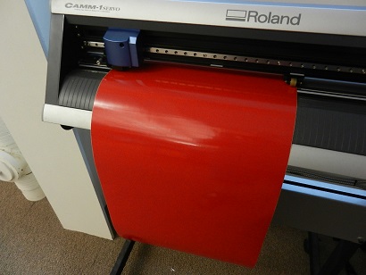
I loaded a sheet of vinyl (seen below) into the cutter and loaded it.
Once loaded I used the dimensions from the machine to wet up the width of my paper.
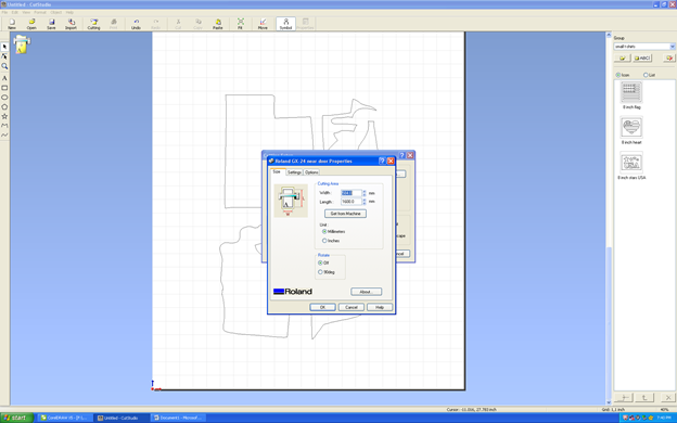
The vinyl sheet I used is 15 inches wide but there is only about 14 iches of cutting space due to the rollers that hold the material.
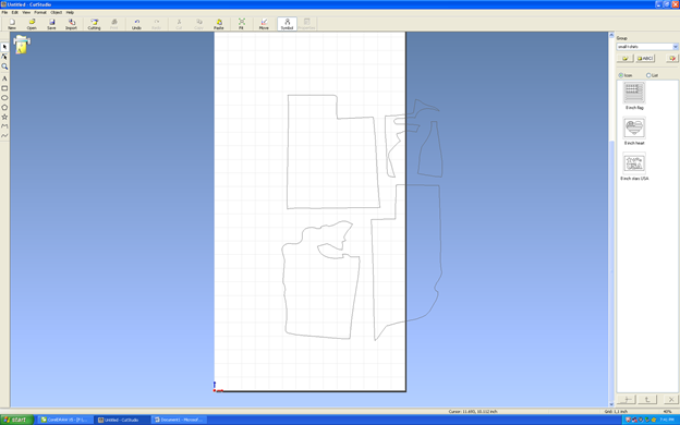
Here I selected the vector and centered them near the bottom of the material.
The leading edge is the origin.
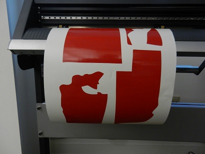
Here you see the piece inserted into the vinyl cutter.
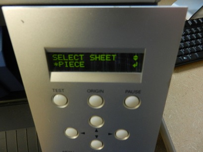
On the control we need to tell the machine whether we have a sigle piece or a roll of material.
The enter key is pushed and the cutting head goes over the part and rolls it back and forth to determine its size.
This is a still shot of the machine cutting.
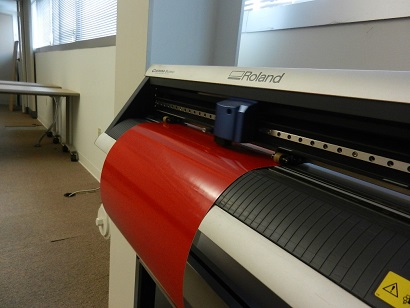
This is not quite a true image. After cutting the vinyl you sould still see a solid red sheet.
The waste material needs to be "weeded" out, or thrown away. I just wanted to let you see the finished cuts.
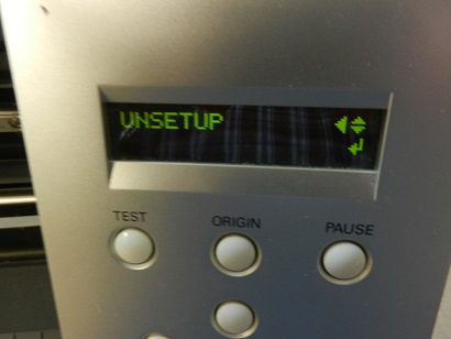
When the cutting is over you must unsetup the machine. It will place the cutting head to the right of the machine in the idle position.